EP2074905A1 - Vorrichtung zum Aufbringen einer kosmetischen Zusammensetzung, die ein Heizorgan umfasst - Google Patents
Vorrichtung zum Aufbringen einer kosmetischen Zusammensetzung, die ein Heizorgan umfasst Download PDFInfo
- Publication number
- EP2074905A1 EP2074905A1 EP08171359A EP08171359A EP2074905A1 EP 2074905 A1 EP2074905 A1 EP 2074905A1 EP 08171359 A EP08171359 A EP 08171359A EP 08171359 A EP08171359 A EP 08171359A EP 2074905 A1 EP2074905 A1 EP 2074905A1
- Authority
- EP
- European Patent Office
- Prior art keywords
- source
- autonomous
- heating member
- voltage
- power
- Prior art date
- Legal status (The legal status is an assumption and is not a legal conclusion. Google has not performed a legal analysis and makes no representation as to the accuracy of the status listed.)
- Granted
Links
Images


Classifications
-
- A—HUMAN NECESSITIES
- A45—HAND OR TRAVELLING ARTICLES
- A45D—HAIRDRESSING OR SHAVING EQUIPMENT; EQUIPMENT FOR COSMETICS OR COSMETIC TREATMENTS, e.g. FOR MANICURING OR PEDICURING
- A45D2/00—Hair-curling or hair-waving appliances ; Appliances for hair dressing treatment not otherwise provided for
- A45D2/48—Eyelash curlers; Eyebrow curlers
-
- A—HUMAN NECESSITIES
- A45—HAND OR TRAVELLING ARTICLES
- A45D—HAIRDRESSING OR SHAVING EQUIPMENT; EQUIPMENT FOR COSMETICS OR COSMETIC TREATMENTS, e.g. FOR MANICURING OR PEDICURING
- A45D40/00—Casings or accessories specially adapted for storing or handling solid or pasty toiletry or cosmetic substances, e.g. shaving soaps or lipsticks
- A45D40/26—Appliances specially adapted for applying pasty paint, e.g. using roller, using a ball
-
- A—HUMAN NECESSITIES
- A45—HAND OR TRAVELLING ARTICLES
- A45D—HAIRDRESSING OR SHAVING EQUIPMENT; EQUIPMENT FOR COSMETICS OR COSMETIC TREATMENTS, e.g. FOR MANICURING OR PEDICURING
- A45D2200/00—Details not otherwise provided for in A45D
- A45D2200/15—Temperature
- A45D2200/155—Heating or cooling means, i.e. for storing or applying cosmetic products at a predetermined temperature
-
- A—HUMAN NECESSITIES
- A46—BRUSHWARE
- A46B—BRUSHES
- A46B2200/00—Brushes characterized by their functions, uses or applications
- A46B2200/10—For human or animal care
- A46B2200/1046—Brush used for applying cosmetics
- A46B2200/1053—Cosmetics applicator specifically for mascara
- A46B2200/106—Cosmetics applicator specifically for mascara including comb like element
Definitions
- the present invention relates to devices for applying a composition, in particular a cosmetic composition, by means of a heating element.
- the invention relates more particularly to the application devices powered from an autonomous source of electrical energy, such as one or more batteries or accumulators.
- Such application devices are known, in particular for applying a composition to the eyelashes.
- the first degree of exhaustion may correspond to the full capacity of the source.
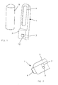
- the application device 1 shown in FIG. figure 1 comprises a housing 2 housing an autonomous electrical energy source 3 and an electric heating element 4, powered from this source of autonomous electrical energy 3 by an electric circuit 10, examples of which are shown in FIGS. figures 2 , 3 , 7 and 9 .
- the application device 1 may have different shapes, the housing 2 being preferably elongated.
- the heating member 4 shown in FIG. figure 1 extends in the extension of the longitudinal axis of the housing.
- the heating member 1 may extend generally transversely to this longitudinal axis, as illustrated in FIG. figure 2 .
- the heating member 4 may comprise at least one electrical resistance, for example a nickel-chromium alloy wire.
- the heating member may for example be as described in one of the applications US 5,853,010 , US 2006/0005851 or JP 2003-3100335 .
- the autonomous power source 3 may comprise one or more 1.5 V batteries, for example of AAA or AA format, or one or more accumulators, for example of the NiMH or lithium polymer type.
- the heating member 4 may be carried by a support which is for example molded of plastic material in one piece with at least a portion of the housing 2. This support may bear only the electric heating member 4 and no temperature sensor for measuring the temperature of the heating member.
- the support may comprise, if necessary, reliefs such as teeth, intended to comb the eyelashes and / or at least one protective relief intended to protect the user in case of accidental contact with the heating member 4, for example transverse ribs covering the heating member.
- the device 1 may optionally comprise a protective cover 8 from covering the electric heating member 4 in the absence of use.
- the housing 2 may comprise a switch 12 on / off and possibly one or more light indicators not shown, for example to signal to the user that the power supply of the heating member is in progress or the need to change the autonomous power source, among others.
- the device may optionally be associated with a charging station for charging the accumulator (s).
- the device comprises an electrical circuit 10 supplying the heating element 4 from the source 3, which is shown diagrammatically in FIG. figure 3 , comprising means 11 for managing the power supply of the heating member 4.
- These means 11 comprise for example a microcontroller programmed to fulfill all or part of the desired functions.
- the circuit 10 may include a delay which maintains the power supply of the electric heating element 4 for a certain period of time after the applicator has been started by the user.
- the management means 11 are for example supplied when the switch 12 is closed, and the supply of the heating member can then be done with a variable power regime, according to for example that the heating member is used to apply of the product or perfect a make-up or must be quickly brought to temperature.
- the heating member 4 is, for example, arranged to be supplied with a nominal operating voltage V w during its use to apply the product or to complete a makeup, the supply at this voltage ensuring the maintenance of the heating member at a temperature for example, between 60 and 70 ° C.
- the voltage of the autonomous power source V smax at full capacity, is greater than V w .
- V w is for example 2V and V smax is for example 3.2 V.
- the supply of the heating member takes place at V smax for example to quickly bring the heating member to temperature.
- the power supply at a voltage V w less than the voltage V s of the source is for example obtained by means of a switched-mode power supply, produced for example from the component marketed under the reference LT 1173 by the company LINEAR TECHNOLOGY according to the the figure 10 .
- the autonomous power source 3 comprises two 1.5 V batteries and the values of L1, R1, R2 and C2 are chosen respectively equal to 220 ⁇ H, 100 k ⁇ and 220 ⁇ F and V w is 2V.
- the circuit 10 can be further arranged to measure the voltage V s across the autonomous power source, compare it with the nominal operating voltage V w of the heating member and, depending on the result of the comparison, act on the power regime of the electric heating element.
- the management means 11 are, for example, arranged for, when the voltage delivered by the source 3 is greater than V w , supplying the heating member 4 with a duty ratio of less than 100%, all the more low as the difference
- the circuit 10 is arranged to deliver to the heating member 4 continuously a voltage substantially equal to V w .
- a switching power supply operating as an elevator can be used for this purpose.
- the circuit 10 does not make it possible to raise the voltage of the source 3.
- FIG. 4 Another example circuit 10 according to the invention wherein the heating member 4 is connected in series with an electronic switching member 13, for example a MOSFET transistor.
- an electronic switching member 13 for example a MOSFET transistor.
- the management means 11 of the power supply are continuously supplied by the source 3 but can go from a standby state, in which their power consumption is very low, to an active state where a certain regulation of the temperature of the heating member is ensured.
- the switch 12 can in this case be in fugitive contact and associated with the management means 11. If necessary, an additional switch cutting the general power supply, not shown, can be provided.
- the circuit management means 11 comprise in the example described a microcontroller arranged to, after detection of a change of state of the switch 12, to go from the standby state to the active state.
- the microcontroller can be arranged to, in the active state, regulate the temperature of the heating element by acting on the electronic switching member 13.
- the power supply of the heating member 4 is effected according to a variable regime depending on the state of exhaustion of the autonomous power source.
- the management means 11 can be arranged to cut the voltage V s so that the average value of the voltage across the electric heating member 4 substantially corresponds to V w , when V s is greater than V w .
- the management means 11 can in particular act on the duty cycle of the supply of the electric heating element by controlling the opening or closing of the electronic switching member 13, the duty ratio being defined as the value ⁇ / T as illustrated at figure 6 .
- the voltage may for example be cut at a frequency 1 / T between 1 Hz and 100 kHz, for example 1kHz.
- the duty cycle is for example 67% at the beginning, then increases to as the voltage V s across the source 3 decreases.
- the heating element is fed continuously at 2V, its temperature remains between 60 and 70 ° C, for example.
- the duty cycle is substantially equal to 100%.
- the microcontroller can store a table of correspondence between the voltage V s and the duty cycle to be applied to the supply voltage of the heating member 4. This table is adapted to a heating element of use voltage V w predefined.
- the management means 11 may be arranged to signal it to the user, for example by a visual or audible signal.
- the power supply of the heating member 4 is carried out according to different regimes depending on the state of exhaustion of the autonomous electrical energy source and / or the operating phase of the applicator, namely on the one hand the service temperature setting or a higher temperature of the electric heating element, or on the other hand the maintenance thereof at the operating temperature.
- the microcontroller detects this action in step 101 and supplies the heating member 4 in a first power regime, corresponding to a heat-up phase.
- This first feed regime can rapidly raise the temperature of the heater from room temperature when the application device is turned on for use.
- the heating element can be supercharged, that is to say that the electrical power it dissipates is greater than that corresponding to its maintenance at the operating temperature.
- the heating member is for example supplied at a voltage greater than V s .
- a switching power supply as shown in FIG. figure 11 is for example used to raise the voltage supplied to the heating member.
- the autonomous power source 3 comprises two 1.5 V batteries and the L and C values are respectively chosen equal to 100 ⁇ H and 100 ⁇ F so that the voltage supplied at the output is equal to 5V for a voltage 3V input.
- step 102 the power supply management means 11 for example measure the voltage V s and act on the switching member 13 to temporarily supply the heating member 4 for a predefined period of time, according to an equal duty cycle. at about 100%.
- the heating member can, as indicated above, according to this first power regime, be supplied with a voltage greater than its operating voltage V w , which can reduce the heating time.
- the power management means 11 determine the duration T 1 during which the heating member 4 must be powered according to the first power regime.
- the microcontroller for example stores a correspondence table between the voltage V s initially measured and the duration T 1 .
- the duration T 1 can respectively be equal to 20s, 30s and 40s.
- the duration of the power supply phase of the high-power heating element can be even lower as the degree of exhaustion of the source 3 is low.
- the heating member 4 is fed during the duration T 1 during step 103.
- step 104 the voltage V s of the autonomous electrical power source 3 is again measured by the power management means 11 which can then feed the heating member according to at least a second power supply.
- supply corresponding for example to an operating phase where the heating member is at the operating temperature and must be maintained at this temperature, which assumes a power supply of the heating member at a lower power than that of the first regime power.
- the management means 11 may, for example, determine the duty cycle as a function of the voltage measured in step 104.
- This duty cycle is, for example, predefined by a correspondence table stored in the microcontroller, having for input for example the voltage V s .
- the duty cycle is determined by the microcontroller according to a mathematical function whose variable is V s .
- the heating member can be fed at step 105 with a determined duty cycle for a duration T 2 , after which the management means 11 detect in step 106 whether the switch 12 is still actuated, to which case the operation according to steps 104 and 105 is continued and, if not, the device returns to the standby mode of step 100.
- the device may comprise two heating members 4 and 4 'may for example be powered independently of one another.
- the two heating members are, for example, arranged on the support of the application device on the same side thereof, for example being superposed, nested or juxtaposed.
- the heating members 4 and 4 ' have, for example, different nominal operating voltages V w and V w .
- the heating member 4 has for example a nominal operating voltage V w greater than a threshold threshold voltage V predefined and the heating member 4 'has for example a nominal operating voltage V w ' less than the threshold voltage Threshold .
- the value of this threshold voltage can be recorded in the microcontroller.
- V threshold is for example about 0.8 V smax .
- the power management means 11 are arranged to measure the voltage V s of the autonomous electrical energy source and to select the heating element or members to be powered according to the voltage V s and / or the phase of the operation, namely the heating of the electric heating element or maintaining it at the temperature of use.
- the device corresponding to the diagram of the figure 7 can operate in at least three feeding regimes, as illustrated in figure 8 .
- Steps 100 and 101 are similar to those described with reference to the figure 5 .
- step 202 the power management means 11 control the simultaneous supply of the two heating members by acting on the switching members 13 and 13 'associated and measure the voltage V s at the terminals of the source 3.
- the management means 11 can at this step 202 determine the duration T 1 of the first power regime as a function of a table of correspondence between the initial voltage V s and the duration T 1 stored in the microcontroller.
- This duration T 1 corresponds for example to the time allowing the applicator to reach the desired temperature, and can thus be shorter when the autonomous energy source is fully charged and longer after partial exhaustion thereof.
- the heating members 4 and 4 ' are for example fed simultaneously.
- step 203 after this phase of warming up the applicator, the voltage V s at the terminals of the autonomous power source is again measured.
- step 204 the management means 11 determine, according to the measured value and the nominal operating voltage of each of the heating members 4 and 4 ', which of the heating members 4 or 4' must be powered.
- the heating element 4 is supplied with a second supply regime at step 205 and if the voltage V s is below this threshold voltage, the heating member 4 'is fed with a third feed regime at step 205.
- the supply of the heating elements in step 205 can be done continuously or in a predefined duty cycle which depends on the voltage V s in a variant.
- Step 205 is performed for a predefined duration T 2 .
- Step 106 is similar to that described with reference to figure 5 .
- the two heating members 4 and 4 ' are electrically connected in series and may or may not be connected to a midpoint, which allows for example to feed only one of the heating organs by shorting the other.
- the application device may comprise more than two heating members.
- the housing may comprise a switch for switching on by heating element.
- the means for managing the power supply of the heating member may not include a microcontroller, the latter being for example replaced by a dedicated analog circuit.
- the intensity traversing the heating element can be measured in order to detect exhaustion of the source and the duty cycle can for example be increased and / or the high supply voltage so that to maintain the current at a preset value.
Landscapes
- Control Of Resistance Heating (AREA)
- Cosmetics (AREA)
- Secondary Cells (AREA)
Applications Claiming Priority (1)
| Application Number | Priority Date | Filing Date | Title |
|---|---|---|---|
| FR0760159A FR2925267B1 (fr) | 2007-12-20 | 2007-12-20 | Dispositif d'application d'une composition cosmetique comportant un organe chauffant. |
Publications (2)
| Publication Number | Publication Date |
|---|---|
| EP2074905A1 true EP2074905A1 (de) | 2009-07-01 |
| EP2074905B1 EP2074905B1 (de) | 2012-03-07 |
Family
ID=39671429
Family Applications (1)
| Application Number | Title | Priority Date | Filing Date |
|---|---|---|---|
| EP08171359A Not-in-force EP2074905B1 (de) | 2007-12-20 | 2008-12-11 | Vorrichtung zum Aufbringen einer kosmetischen Zusammensetzung, die ein Heizorgan umfasst |
Country Status (5)
| Country | Link |
|---|---|
| US (1) | US8698042B2 (de) |
| EP (1) | EP2074905B1 (de) |
| AT (1) | ATE547963T1 (de) |
| ES (1) | ES2381887T3 (de) |
| FR (1) | FR2925267B1 (de) |
Families Citing this family (5)
| Publication number | Priority date | Publication date | Assignee | Title |
|---|---|---|---|---|
| FR2912041B1 (fr) * | 2007-02-06 | 2011-03-11 | Oreal | Ensemble pour le maquillage des cils, comportant un dispositif d'application comprenant un support chauffant |
| FR2927233B1 (fr) * | 2008-02-08 | 2011-11-11 | Oreal | Dispositif pour l'application d'un produit cosmetique, comportant un organe chauffant |
| US8308383B2 (en) * | 2010-03-26 | 2012-11-13 | Elc Management, Llc | Heated mascara applicator and suitable compositions |
| GB2566928A (en) * | 2017-08-12 | 2019-04-03 | Therecea Oconnor | Battery operated heated wax melt device and method for mascara |
| CN110167207A (zh) * | 2019-07-02 | 2019-08-23 | 厦门美图之家科技有限公司 | 美容仪和加热控制方法 |
Citations (5)
| Publication number | Priority date | Publication date | Assignee | Title |
|---|---|---|---|---|
| US5853010A (en) | 1996-12-18 | 1998-12-29 | Suh; Jeong Joo | Eyelash curler |
| WO2000040112A1 (en) * | 1998-12-31 | 2000-07-13 | Youm, Hyoun, Jik | Eyelash curler |
| JP2003310335A (ja) | 2002-04-19 | 2003-11-05 | Matsushita Electric Works Ltd | 睫毛成形具 |
| US20060005851A1 (en) | 2004-07-06 | 2006-01-12 | Cho Yong H | Heated eyelash curler |
| WO2007143430A2 (en) * | 2006-06-07 | 2007-12-13 | Elc Management Llc | Cosmetic applicators containing heating elements |
Family Cites Families (20)
| Publication number | Priority date | Publication date | Assignee | Title |
|---|---|---|---|---|
| US2630516A (en) * | 1949-08-09 | 1953-03-03 | Clifford A Rausch | Eyelash processor |
| US3012126A (en) * | 1959-07-02 | 1961-12-05 | Duffers Ass | Temperature control system |
| US4442343A (en) * | 1982-04-16 | 1984-04-10 | Koffee Keeper, Inc. | Adjustable cup and fluid heater |
| US5775344A (en) | 1996-02-09 | 1998-07-07 | Clay; Mary A. | Cosmetic container and applicator with heating apparatus |
| US6040560A (en) * | 1996-10-22 | 2000-03-21 | Philip Morris Incorporated | Power controller and method of operating an electrical smoking system |
| JP4523122B2 (ja) * | 2000-07-05 | 2010-08-11 | 株式会社三社電機製作所 | 電源装置 |
| US6891130B2 (en) * | 2000-09-15 | 2005-05-10 | Walter Evanyk | Appliance for dispensing melt adhesive with variable duty cycle and method of implementing |
| US6946623B2 (en) * | 2000-09-15 | 2005-09-20 | Powerpulse Technologies, L.P. | Appliance for liquefying solder with variable duty cycle and method of implementing |
| US6770853B2 (en) * | 2002-10-22 | 2004-08-03 | Vector Products, Inc. | PWM controller for DC powered heating blanket |
| FR2852795B1 (fr) | 2003-03-24 | 2005-05-06 | Oreal | Ensemble de conditionnement et d'application d'un produit cosmetique et ou de soins comportant un moyen chauffant |
| FR2853505B1 (fr) | 2003-04-11 | 2005-05-20 | Oreal | Ensemble de conditionnement et d'application d'un produit de maquillage et/ou de soin |
| US20050220828A1 (en) | 2003-10-31 | 2005-10-06 | The Procter & Gamble Company | Treatment of keratinous tissue |
| US7084379B2 (en) * | 2004-03-22 | 2006-08-01 | Ngk Spark Plug Co., Ltd. | Control apparatus for gas sensor |
| US7465114B2 (en) | 2004-08-11 | 2008-12-16 | Elc Management Llc | Vibrating mascara applicator, suitable compositions and method of use |
| US7608805B2 (en) * | 2005-01-14 | 2009-10-27 | Hakko Corporation | Control system for battery powered heating device |
| JP5019814B2 (ja) * | 2005-10-14 | 2012-09-05 | 株式会社リコー | 画像形成装置および電力制御方法 |
| KR100846443B1 (ko) | 2006-03-31 | 2008-07-16 | 김태연 | 히팅 마스카라 |
| US7448814B2 (en) | 2006-06-07 | 2008-11-11 | Elc Management Llc | Cosmetic dispensing devices containing heating elements |
| US20080235853A1 (en) * | 2007-03-30 | 2008-10-02 | Kevin James Sousa | Heated Earmuff With Improved Frame and Heating Element |
| FR2925268B1 (fr) * | 2007-12-20 | 2010-11-05 | Oreal | Dispositif de prelevement et d'application d'un produit cosmetique. |
-
2007
- 2007-12-20 FR FR0760159A patent/FR2925267B1/fr not_active Expired - Fee Related
-
2008
- 2008-12-11 AT AT08171359T patent/ATE547963T1/de active
- 2008-12-11 ES ES08171359T patent/ES2381887T3/es active Active
- 2008-12-11 EP EP08171359A patent/EP2074905B1/de not_active Not-in-force
- 2008-12-18 US US12/338,004 patent/US8698042B2/en not_active Expired - Fee Related
Patent Citations (5)
| Publication number | Priority date | Publication date | Assignee | Title |
|---|---|---|---|---|
| US5853010A (en) | 1996-12-18 | 1998-12-29 | Suh; Jeong Joo | Eyelash curler |
| WO2000040112A1 (en) * | 1998-12-31 | 2000-07-13 | Youm, Hyoun, Jik | Eyelash curler |
| JP2003310335A (ja) | 2002-04-19 | 2003-11-05 | Matsushita Electric Works Ltd | 睫毛成形具 |
| US20060005851A1 (en) | 2004-07-06 | 2006-01-12 | Cho Yong H | Heated eyelash curler |
| WO2007143430A2 (en) * | 2006-06-07 | 2007-12-13 | Elc Management Llc | Cosmetic applicators containing heating elements |
Also Published As
| Publication number | Publication date |
|---|---|
| ES2381887T3 (es) | 2012-06-01 |
| EP2074905B1 (de) | 2012-03-07 |
| US20090159583A1 (en) | 2009-06-25 |
| FR2925267A1 (fr) | 2009-06-26 |
| ATE547963T1 (de) | 2012-03-15 |
| US8698042B2 (en) | 2014-04-15 |
| FR2925267B1 (fr) | 2010-01-08 |
Similar Documents
| Publication | Publication Date | Title |
|---|---|---|
| EP2074905B1 (de) | Vorrichtung zum Aufbringen einer kosmetischen Zusammensetzung, die ein Heizorgan umfasst | |
| EP1462025B1 (de) | Behältnis mit beheiztem Abstreifer | |
| EP2074906B1 (de) | Entnahme- und Applikationsvorrichtung eines Kosmetikprodukts | |
| EP1685637B1 (de) | Stromautonomer tragbarer elektrowerkzeugsatz | |
| FR2467501A1 (fr) | Dispositif de charge pour un accumulateur | |
| FR2998108A1 (fr) | Systeme de pre-charge d'une capacite par une batterie | |
| EP2665120A1 (de) | Verfahren und System zum Ausgleich von Zellen, die Bestandteil einer Batterie sind | |
| WO2003041189A2 (fr) | Procede et dispositif d'alimentation en energie electrique d'un appareil | |
| EP0768745B1 (de) | Verfahren zum Laden von gasdichten Nickel-Cadmium-Batterien | |
| EP2476158B1 (de) | Verfahren zur verwendung eines an eine batterie angeschlossenen autonomen systems | |
| EP2079125B1 (de) | Verfahren zur Steuerung des Aufladevorgangs einer Batterie | |
| FR2816463A1 (fr) | Dispositif d'alimentation d'un equipement electrique en energie electrique continue | |
| WO2013034854A2 (fr) | Procédé et dispositif de recharge optimisée de batterie électrique | |
| EP1801949B1 (de) | Batterie, Elektrogerät und Versorgungsverfahren mit dem Einsatz eines Batteriekurzschlussmittels | |
| CA2585894C (fr) | Procede de charge de batterie avec compensation de resistance interne, chargeur et batterie pour la mise en oeuvre de ce procede | |
| FR2800212A1 (fr) | Systeme de gestion de charge pour batterie d'accumulateurs electriques et notamment d'une batterie composee de cellules au lithium | |
| EP0856625A1 (de) | Elektrisches Kraftfahrzeugtürschloss mit einer Notstrombatterie mit gesteuerter Entladung | |
| FR2709225A1 (fr) | Appareil pour clôture électrique. | |
| EP2908605A1 (de) | Elektronische Vorrichtung zur Stromversorgung einer Elektrolumineszenzdiode | |
| EP3591476B1 (de) | Thermoelektrische armbanduhr, die von ihrem träger getestet werden kann | |
| EP1848087B1 (de) | Vorrichtung und Verfahren zur Selbstregulierung der Ladung eines elektrochemischen Generators | |
| CH707569A2 (fr) | Dispositif portable de conversion DC/DC incluant un algorithme MPPT pour le chargement optimal d'une batterie à partir d'un panneau photovoltaïque. | |
| FR2722336A1 (fr) | Procede pour maintenir la charge d'un accumulateur et surveiller sa capacite residuelle, son etat de charge et son vieillissement | |
| EP3311461B1 (de) | Nomadische ladevorrichtung und verfahren zur verwaltung der internen ladung der vorrichtung | |
| FR2865097A1 (fr) | Procede pour augmenter l'autonomie d'un electrificateur de cloture et electrificateur associe |
Legal Events
| Date | Code | Title | Description |
|---|---|---|---|
| PUAI | Public reference made under article 153(3) epc to a published international application that has entered the european phase |
Free format text: ORIGINAL CODE: 0009012 |
|
| 17P | Request for examination filed |
Effective date: 20081211 |
|
| AK | Designated contracting states |
Kind code of ref document: A1 Designated state(s): AT BE BG CH CY CZ DE DK EE ES FI FR GB GR HR HU IE IS IT LI LT LU LV MC MT NL NO PL PT RO SE SI SK TR |
|
| AX | Request for extension of the european patent |
Extension state: AL BA MK RS |
|
| 17Q | First examination report despatched |
Effective date: 20090814 |
|
| AKX | Designation fees paid |
Designated state(s): AT BE BG CH CY CZ DE DK EE ES FI FR GB GR HR HU IE IS IT LI LT LU LV MC MT NL NO PL PT RO SE SI SK TR |
|
| GRAP | Despatch of communication of intention to grant a patent |
Free format text: ORIGINAL CODE: EPIDOSNIGR1 |
|
| GRAS | Grant fee paid |
Free format text: ORIGINAL CODE: EPIDOSNIGR3 |
|
| GRAA | (expected) grant |
Free format text: ORIGINAL CODE: 0009210 |
|
| AK | Designated contracting states |
Kind code of ref document: B1 Designated state(s): AT BE BG CH CY CZ DE DK EE ES FI FR GB GR HR HU IE IS IT LI LT LU LV MC MT NL NO PL PT RO SE SI SK TR |
|
| REG | Reference to a national code |
Ref country code: GB Ref legal event code: FG4D Free format text: NOT ENGLISH |
|
| REG | Reference to a national code |
Ref country code: AT Ref legal event code: REF Ref document number: 547963 Country of ref document: AT Kind code of ref document: T Effective date: 20120315 Ref country code: CH Ref legal event code: EP |
|
| REG | Reference to a national code |
Ref country code: IE Ref legal event code: FG4D Free format text: LANGUAGE OF EP DOCUMENT: FRENCH |
|
| REG | Reference to a national code |
Ref country code: DE Ref legal event code: R096 Ref document number: 602008013903 Country of ref document: DE Effective date: 20120503 |
|
| REG | Reference to a national code |
Ref country code: ES Ref legal event code: FG2A Ref document number: 2381887 Country of ref document: ES Kind code of ref document: T3 Effective date: 20120601 |
|
| REG | Reference to a national code |
Ref country code: NL Ref legal event code: VDEP Effective date: 20120307 |
|
| PG25 | Lapsed in a contracting state [announced via postgrant information from national office to epo] |
Ref country code: HR Free format text: LAPSE BECAUSE OF FAILURE TO SUBMIT A TRANSLATION OF THE DESCRIPTION OR TO PAY THE FEE WITHIN THE PRESCRIBED TIME-LIMIT Effective date: 20120307 Ref country code: NO Free format text: LAPSE BECAUSE OF FAILURE TO SUBMIT A TRANSLATION OF THE DESCRIPTION OR TO PAY THE FEE WITHIN THE PRESCRIBED TIME-LIMIT Effective date: 20120607 Ref country code: LT Free format text: LAPSE BECAUSE OF FAILURE TO SUBMIT A TRANSLATION OF THE DESCRIPTION OR TO PAY THE FEE WITHIN THE PRESCRIBED TIME-LIMIT Effective date: 20120307 Ref country code: NL Free format text: LAPSE BECAUSE OF FAILURE TO SUBMIT A TRANSLATION OF THE DESCRIPTION OR TO PAY THE FEE WITHIN THE PRESCRIBED TIME-LIMIT Effective date: 20120307 |
|
| LTIE | Lt: invalidation of european patent or patent extension |
Effective date: 20120307 |
|
| PG25 | Lapsed in a contracting state [announced via postgrant information from national office to epo] |
Ref country code: FI Free format text: LAPSE BECAUSE OF FAILURE TO SUBMIT A TRANSLATION OF THE DESCRIPTION OR TO PAY THE FEE WITHIN THE PRESCRIBED TIME-LIMIT Effective date: 20120307 Ref country code: GR Free format text: LAPSE BECAUSE OF FAILURE TO SUBMIT A TRANSLATION OF THE DESCRIPTION OR TO PAY THE FEE WITHIN THE PRESCRIBED TIME-LIMIT Effective date: 20120608 Ref country code: LV Free format text: LAPSE BECAUSE OF FAILURE TO SUBMIT A TRANSLATION OF THE DESCRIPTION OR TO PAY THE FEE WITHIN THE PRESCRIBED TIME-LIMIT Effective date: 20120307 |
|
| REG | Reference to a national code |
Ref country code: AT Ref legal event code: MK05 Ref document number: 547963 Country of ref document: AT Kind code of ref document: T Effective date: 20120307 |
|
| PG25 | Lapsed in a contracting state [announced via postgrant information from national office to epo] |
Ref country code: CY Free format text: LAPSE BECAUSE OF FAILURE TO SUBMIT A TRANSLATION OF THE DESCRIPTION OR TO PAY THE FEE WITHIN THE PRESCRIBED TIME-LIMIT Effective date: 20120307 |
|
| PG25 | Lapsed in a contracting state [announced via postgrant information from national office to epo] |
Ref country code: IS Free format text: LAPSE BECAUSE OF FAILURE TO SUBMIT A TRANSLATION OF THE DESCRIPTION OR TO PAY THE FEE WITHIN THE PRESCRIBED TIME-LIMIT Effective date: 20120707 Ref country code: SE Free format text: LAPSE BECAUSE OF FAILURE TO SUBMIT A TRANSLATION OF THE DESCRIPTION OR TO PAY THE FEE WITHIN THE PRESCRIBED TIME-LIMIT Effective date: 20120307 Ref country code: PL Free format text: LAPSE BECAUSE OF FAILURE TO SUBMIT A TRANSLATION OF THE DESCRIPTION OR TO PAY THE FEE WITHIN THE PRESCRIBED TIME-LIMIT Effective date: 20120307 Ref country code: EE Free format text: LAPSE BECAUSE OF FAILURE TO SUBMIT A TRANSLATION OF THE DESCRIPTION OR TO PAY THE FEE WITHIN THE PRESCRIBED TIME-LIMIT Effective date: 20120307 Ref country code: CZ Free format text: LAPSE BECAUSE OF FAILURE TO SUBMIT A TRANSLATION OF THE DESCRIPTION OR TO PAY THE FEE WITHIN THE PRESCRIBED TIME-LIMIT Effective date: 20120307 Ref country code: RO Free format text: LAPSE BECAUSE OF FAILURE TO SUBMIT A TRANSLATION OF THE DESCRIPTION OR TO PAY THE FEE WITHIN THE PRESCRIBED TIME-LIMIT Effective date: 20120307 Ref country code: SI Free format text: LAPSE BECAUSE OF FAILURE TO SUBMIT A TRANSLATION OF THE DESCRIPTION OR TO PAY THE FEE WITHIN THE PRESCRIBED TIME-LIMIT Effective date: 20120307 |
|
| PG25 | Lapsed in a contracting state [announced via postgrant information from national office to epo] |
Ref country code: SK Free format text: LAPSE BECAUSE OF FAILURE TO SUBMIT A TRANSLATION OF THE DESCRIPTION OR TO PAY THE FEE WITHIN THE PRESCRIBED TIME-LIMIT Effective date: 20120307 Ref country code: PT Free format text: LAPSE BECAUSE OF FAILURE TO SUBMIT A TRANSLATION OF THE DESCRIPTION OR TO PAY THE FEE WITHIN THE PRESCRIBED TIME-LIMIT Effective date: 20120709 |
|
| PLBE | No opposition filed within time limit |
Free format text: ORIGINAL CODE: 0009261 |
|
| STAA | Information on the status of an ep patent application or granted ep patent |
Free format text: STATUS: NO OPPOSITION FILED WITHIN TIME LIMIT |
|
| PG25 | Lapsed in a contracting state [announced via postgrant information from national office to epo] |
Ref country code: AT Free format text: LAPSE BECAUSE OF FAILURE TO SUBMIT A TRANSLATION OF THE DESCRIPTION OR TO PAY THE FEE WITHIN THE PRESCRIBED TIME-LIMIT Effective date: 20120307 Ref country code: DK Free format text: LAPSE BECAUSE OF FAILURE TO SUBMIT A TRANSLATION OF THE DESCRIPTION OR TO PAY THE FEE WITHIN THE PRESCRIBED TIME-LIMIT Effective date: 20120307 |
|
| 26N | No opposition filed |
Effective date: 20121210 |
|
| REG | Reference to a national code |
Ref country code: DE Ref legal event code: R097 Ref document number: 602008013903 Country of ref document: DE Effective date: 20121210 |
|
| BERE | Be: lapsed |
Owner name: L'OREAL Effective date: 20121231 |
|
| PG25 | Lapsed in a contracting state [announced via postgrant information from national office to epo] |
Ref country code: MC Free format text: LAPSE BECAUSE OF NON-PAYMENT OF DUE FEES Effective date: 20121231 Ref country code: BG Free format text: LAPSE BECAUSE OF FAILURE TO SUBMIT A TRANSLATION OF THE DESCRIPTION OR TO PAY THE FEE WITHIN THE PRESCRIBED TIME-LIMIT Effective date: 20120607 |
|
| REG | Reference to a national code |
Ref country code: CH Ref legal event code: PL |
|
| REG | Reference to a national code |
Ref country code: IE Ref legal event code: MM4A |
|
| PG25 | Lapsed in a contracting state [announced via postgrant information from national office to epo] |
Ref country code: BE Free format text: LAPSE BECAUSE OF NON-PAYMENT OF DUE FEES Effective date: 20121231 |
|
| PG25 | Lapsed in a contracting state [announced via postgrant information from national office to epo] |
Ref country code: LI Free format text: LAPSE BECAUSE OF NON-PAYMENT OF DUE FEES Effective date: 20121231 Ref country code: CH Free format text: LAPSE BECAUSE OF NON-PAYMENT OF DUE FEES Effective date: 20121231 Ref country code: IE Free format text: LAPSE BECAUSE OF NON-PAYMENT OF DUE FEES Effective date: 20121211 |
|
| PG25 | Lapsed in a contracting state [announced via postgrant information from national office to epo] |
Ref country code: MT Free format text: LAPSE BECAUSE OF FAILURE TO SUBMIT A TRANSLATION OF THE DESCRIPTION OR TO PAY THE FEE WITHIN THE PRESCRIBED TIME-LIMIT Effective date: 20120307 |
|
| PG25 | Lapsed in a contracting state [announced via postgrant information from national office to epo] |
Ref country code: TR Free format text: LAPSE BECAUSE OF FAILURE TO SUBMIT A TRANSLATION OF THE DESCRIPTION OR TO PAY THE FEE WITHIN THE PRESCRIBED TIME-LIMIT Effective date: 20120307 |
|
| PG25 | Lapsed in a contracting state [announced via postgrant information from national office to epo] |
Ref country code: LU Free format text: LAPSE BECAUSE OF NON-PAYMENT OF DUE FEES Effective date: 20121211 |
|
| PG25 | Lapsed in a contracting state [announced via postgrant information from national office to epo] |
Ref country code: HU Free format text: LAPSE BECAUSE OF FAILURE TO SUBMIT A TRANSLATION OF THE DESCRIPTION OR TO PAY THE FEE WITHIN THE PRESCRIBED TIME-LIMIT Effective date: 20081211 |
|
| REG | Reference to a national code |
Ref country code: FR Ref legal event code: PLFP Year of fee payment: 8 |
|
| REG | Reference to a national code |
Ref country code: FR Ref legal event code: PLFP Year of fee payment: 9 |
|
| REG | Reference to a national code |
Ref country code: FR Ref legal event code: PLFP Year of fee payment: 10 |
|
| PGFP | Annual fee paid to national office [announced via postgrant information from national office to epo] |
Ref country code: DE Payment date: 20181127 Year of fee payment: 11 |
|
| PGFP | Annual fee paid to national office [announced via postgrant information from national office to epo] |
Ref country code: FR Payment date: 20181123 Year of fee payment: 11 Ref country code: GB Payment date: 20181205 Year of fee payment: 11 |
|
| PGFP | Annual fee paid to national office [announced via postgrant information from national office to epo] |
Ref country code: IT Payment date: 20181220 Year of fee payment: 11 Ref country code: ES Payment date: 20190102 Year of fee payment: 11 |
|
| REG | Reference to a national code |
Ref country code: DE Ref legal event code: R119 Ref document number: 602008013903 Country of ref document: DE |
|
| GBPC | Gb: european patent ceased through non-payment of renewal fee |
Effective date: 20191211 |
|
| PG25 | Lapsed in a contracting state [announced via postgrant information from national office to epo] |
Ref country code: FR Free format text: LAPSE BECAUSE OF NON-PAYMENT OF DUE FEES Effective date: 20191231 Ref country code: IT Free format text: LAPSE BECAUSE OF NON-PAYMENT OF DUE FEES Effective date: 20191211 Ref country code: DE Free format text: LAPSE BECAUSE OF NON-PAYMENT OF DUE FEES Effective date: 20200701 Ref country code: GB Free format text: LAPSE BECAUSE OF NON-PAYMENT OF DUE FEES Effective date: 20191211 |
|
| REG | Reference to a national code |
Ref country code: ES Ref legal event code: FD2A Effective date: 20210602 |
|
| PG25 | Lapsed in a contracting state [announced via postgrant information from national office to epo] |
Ref country code: ES Free format text: LAPSE BECAUSE OF NON-PAYMENT OF DUE FEES Effective date: 20191212 |