EP2074969B1 - Éléments portables pour systèmes de restriction implantables - Google Patents
Éléments portables pour systèmes de restriction implantables Download PDFInfo
- Publication number
- EP2074969B1 EP2074969B1 EP08254033A EP08254033A EP2074969B1 EP 2074969 B1 EP2074969 B1 EP 2074969B1 EP 08254033 A EP08254033 A EP 08254033A EP 08254033 A EP08254033 A EP 08254033A EP 2074969 B1 EP2074969 B1 EP 2074969B1
- Authority
- EP
- European Patent Office
- Prior art keywords
- external device
- communicating member
- implantable
- patient
- wearable element
- Prior art date
- Legal status (The legal status is an assumption and is not a legal conclusion. Google has not performed a legal analysis and makes no representation as to the accuracy of the status listed.)
- Not-in-force
Links
- 230000001939 inductive effect Effects 0.000 claims description 46
- 230000007246 mechanism Effects 0.000 claims description 12
- 230000008878 coupling Effects 0.000 claims description 9
- 238000010168 coupling process Methods 0.000 claims description 9
- 238000005859 coupling reaction Methods 0.000 claims description 9
- 230000004044 response Effects 0.000 claims description 4
- 210000002784 stomach Anatomy 0.000 description 19
- 230000002496 gastric effect Effects 0.000 description 15
- 238000000034 method Methods 0.000 description 10
- 238000004891 communication Methods 0.000 description 9
- 239000007943 implant Substances 0.000 description 9
- 238000012544 monitoring process Methods 0.000 description 8
- 238000005259 measurement Methods 0.000 description 6
- 230000000694 effects Effects 0.000 description 5
- 239000012530 fluid Substances 0.000 description 5
- 239000000463 material Substances 0.000 description 5
- 208000008589 Obesity Diseases 0.000 description 4
- 239000000853 adhesive Substances 0.000 description 4
- 230000001070 adhesive effect Effects 0.000 description 4
- 230000037406 food intake Effects 0.000 description 4
- 235000012631 food intake Nutrition 0.000 description 4
- 230000006870 function Effects 0.000 description 4
- 238000002347 injection Methods 0.000 description 4
- 239000007924 injection Substances 0.000 description 4
- 238000012546 transfer Methods 0.000 description 4
- WHXSMMKQMYFTQS-UHFFFAOYSA-N Lithium Chemical compound [Li] WHXSMMKQMYFTQS-UHFFFAOYSA-N 0.000 description 3
- 229910052744 lithium Inorganic materials 0.000 description 3
- 229910052751 metal Inorganic materials 0.000 description 3
- 239000002184 metal Substances 0.000 description 3
- 229920000642 polymer Polymers 0.000 description 3
- RYGMFSIKBFXOCR-UHFFFAOYSA-N Copper Chemical compound [Cu] RYGMFSIKBFXOCR-UHFFFAOYSA-N 0.000 description 2
- 230000004913 activation Effects 0.000 description 2
- 208000012696 congenital leptin deficiency Diseases 0.000 description 2
- 235000019138 food restriction Nutrition 0.000 description 2
- 238000004519 manufacturing process Methods 0.000 description 2
- 230000013011 mating Effects 0.000 description 2
- 238000012806 monitoring device Methods 0.000 description 2
- 230000005404 monopole Effects 0.000 description 2
- 208000001022 morbid obesity Diseases 0.000 description 2
- 235000020824 obesity Nutrition 0.000 description 2
- 239000012858 resilient material Substances 0.000 description 2
- 238000012552 review Methods 0.000 description 2
- 229920000742 Cotton Polymers 0.000 description 1
- 239000004677 Nylon Substances 0.000 description 1
- 229920002334 Spandex Polymers 0.000 description 1
- 230000003187 abdominal effect Effects 0.000 description 1
- 239000002253 acid Substances 0.000 description 1
- 230000009471 action Effects 0.000 description 1
- 230000008901 benefit Effects 0.000 description 1
- 230000005540 biological transmission Effects 0.000 description 1
- 230000037396 body weight Effects 0.000 description 1
- 238000004140 cleaning Methods 0.000 description 1
- 229910052802 copper Inorganic materials 0.000 description 1
- 239000010949 copper Substances 0.000 description 1
- 230000002354 daily effect Effects 0.000 description 1
- 238000009826 distribution Methods 0.000 description 1
- 239000013013 elastic material Substances 0.000 description 1
- 230000005611 electricity Effects 0.000 description 1
- 230000003628 erosive effect Effects 0.000 description 1
- 230000003203 everyday effect Effects 0.000 description 1
- 239000004744 fabric Substances 0.000 description 1
- 239000003292 glue Substances 0.000 description 1
- 230000036541 health Effects 0.000 description 1
- 230000008821 health effect Effects 0.000 description 1
- 230000005802 health problem Effects 0.000 description 1
- 238000012986 modification Methods 0.000 description 1
- 230000004048 modification Effects 0.000 description 1
- 229920001778 nylon Polymers 0.000 description 1
- 239000012466 permeate Substances 0.000 description 1
- 230000004962 physiological condition Effects 0.000 description 1
- 239000004033 plastic Substances 0.000 description 1
- 229920000728 polyester Polymers 0.000 description 1
- 239000004759 spandex Substances 0.000 description 1
- 239000004753 textile Substances 0.000 description 1
Images



Classifications
-
- A—HUMAN NECESSITIES
- A61—MEDICAL OR VETERINARY SCIENCE; HYGIENE
- A61F—FILTERS IMPLANTABLE INTO BLOOD VESSELS; PROSTHESES; DEVICES PROVIDING PATENCY TO, OR PREVENTING COLLAPSING OF, TUBULAR STRUCTURES OF THE BODY, e.g. STENTS; ORTHOPAEDIC, NURSING OR CONTRACEPTIVE DEVICES; FOMENTATION; TREATMENT OR PROTECTION OF EYES OR EARS; BANDAGES, DRESSINGS OR ABSORBENT PADS; FIRST-AID KITS
- A61F5/00—Orthopaedic methods or devices for non-surgical treatment of bones or joints; Nursing devices ; Anti-rape devices
- A61F5/0003—Apparatus for the treatment of obesity; Anti-eating devices
- A61F5/0013—Implantable devices or invasive measures
- A61F5/005—Gastric bands
- A61F5/0053—Gastric bands remotely adjustable
- A61F5/0059—Gastric bands remotely adjustable with wireless means
-
- A—HUMAN NECESSITIES
- A41—WEARING APPAREL
- A41D—OUTERWEAR; PROTECTIVE GARMENTS; ACCESSORIES
- A41D13/00—Professional, industrial or sporting protective garments, e.g. surgeons' gowns or garments protecting against blows or punches
- A41D13/12—Surgeons' or patients' gowns or dresses
- A41D13/1236—Patients' garments
- A41D13/1245—Patients' garments for the upper part of the body
-
- A—HUMAN NECESSITIES
- A41—WEARING APPAREL
- A41D—OUTERWEAR; PROTECTIVE GARMENTS; ACCESSORIES
- A41D13/00—Professional, industrial or sporting protective garments, e.g. surgeons' gowns or garments protecting against blows or punches
- A41D13/12—Surgeons' or patients' gowns or dresses
- A41D13/1236—Patients' garments
- A41D13/1281—Patients' garments with incorporated means for medical monitoring
Definitions
- the present invention relates to wearable elements for use with implantable restriction devices.
- Obesity is becoming a growing concern, particularly in the United States, as the number of obese people continues to increase, and more is learned about the negative health effects of obesity.
- Morbid obesity in which a person is 100 pounds or more over ideal body weight, in particular poses significant risks for severe health problems. Accordingly, a great deal of attention is being focused on treating obese patients.
- One method of treating morbid obesity has been to place a restriction device, such as an elongated band, about the upper portion of the stomach.
- Gastric bands have typically comprised a fluid-filled elastomeric balloon with fixed endpoints that encircles the stomach just inferior to the esophageal-gastric junction to form a small gastric pouch above the band and a reduced stoma opening in the stomach.
- the band When fluid is infused into the balloon, the band expands against the stomach creating a food intake restriction or stoma in the stomach. To decrease this restriction, fluid is removed from the band. The effect of the band is to reduce the available stomach volume and thus the amount of food that can be consumed before becoming “full.”
- Food restriction devices have also comprised mechanically adjusted bands that similarly encircle the upper portion of the stomach. These bands include any number of resilient materials or gearing devices, as well as drive members, for adjusting the bands. Additionally, gastric bands have been developed that include both hydraulic and mechanical drive elements.
- An example of such an adjustable gastric band is disclosed in U.S. Pat. No. 6,067,991 , entitled “Mechanical Food Intake Restriction Device” which issued on May 30, 2000 It is also known to restrict the available food volume in the stomach cavity by implanting an inflatable elastomeric balloon within the stomach cavity itself. The balloon is filled with a fluid to expand against the stomach walls and, thereby, decrease the available food volume within the stomach.
- US2009/0306462A1 describes a system for controlling a controllable gastric band, comprising a control unit, wherein the control unit is in the form of a watch. At least one sensor is present for detecting the pressure on the gastric wall. This sensor is connected with a device for the wireless transmission of the detected pressure values to the control unit.
- EP 1736123 A1 describes remote monitoring and adjustment of a food intake restriction device.
- the device may include a data logger with TET and telemetry coils.
- the data logger may be worn on a belt about the patient's waist to position the coils adjacent an injection port when the port is implanted on the patient's abdominal area.
- a system for forming a restriction in a patient includes an implantable restriction device adapted to form a restriction in a patient and an implantable communicating member configured to send and/or receive a wireless signal.
- the restriction device can include, for example, a gastric band and a housing in communication with the gastric band.
- the system further includes a wearable element configured to be worn by a patient and an external device coupled to the wearable element which is configured to send and/or receive a wireless signal to communicate with the implantable communicating member.
- the external device is disposable at a plurality of locations relative to the wearable element.
- the external device can have a variety of configurations, and in one embodiment the external device can be an antenna positionable in proximity to the implantable communicating member and configured to receive data from the implantable communicating member. In another embodiment, the external device can be configured to send power to the implantable communicating member. In still another embodiment, the implantable communicating member can be an internal inductive coil and the external device can be an external inductive coil and the coils can be configured to resonate at substantially the same frequency to maximize power coupling.
- the wearable element also includes an alignment mechanism configured to indicate proper alignment between the external device and the implantable communicating member.
- the system can include a first external device and a second external device that are coupled to one another and are positionable at a plurality of locations on the wearable element at a distance apart from one another.
- the first external device can be configured to receive data from the implantable communicating member and the second external device can also optionally be configured to provide power to the first external device.
- the wearable element can also have a variety of configurations, and in one exemplary embodiment the wearable element can be a flexible battery adapted to flex in response to motion of a user wearing the flexible battery. In another exemplary embodiment, the wearable element can be formed from a plurality of elastic straps. In addition, the wearable element can be adjustable to a variety of patient sizes and shapes. In still another embodiment, the wearable element can be a vest, or a sash. In other aspects, the wearable element can include at least one pocket formed therein which is movable relative to the wearable element. In one embodiment, the pocket includes at least one battery disposed therein which is configured to provide power to the external device.
- the method can include positioning an external device on a wearable element worn by a patient at one of a plurality of locations to align the external device with an implantable communicating member on an implantable restriction device implanted in the patient.
- the external device can be activated to wirelessly transfer a signal through tissue to the implantable communicating member.
- the external device can deliver energy to the implantable communicating member and/or receive data from the implantable communicating member.
- the external device can be an external inductive coil and the implantable communicating member can be an internal inductive coil and the method can further include using inductive coupling between the external coil and the internal coil to generate power.
- the two coils can be tuned to resonate at substantially the same frequency to maximize power coupling.
- the external device can be positioned at a variety of locations, in one exemplary embodiment the external device can be positioned on a skin surface in proximity to the implantable communicating member.
- the external device can be positioned on the wearable element or at a distance apart from the wearable element.
- the wearable element can include a plurality of flexible straps, and the external device can be removably mated to the flexible straps in proximity to the implantable communicating member.
- the external device can be disposed within a pocket on the wearable element.
- the wearable element can be a flexible battery.
- the external device can be coupled to the flexible battery and can deliver energy to the implantable communicating member generated by the flexible battery.
- FIG. 1A is a representation of an implantable restriction device implanted in a patient to form a restriction in the patient's stomach;
- FIG. 1B is a perspective view of the implantable restriction device of FIG. 1A ;
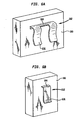
- FIG. 2A is a perspective view of one embodiment of a wearable element having pockets disposed at a plurality of locations thereon and including external devices disposed within the pockets;
- FIG. 2B is a perspective view of an exemplary pocket of FIG. 2A with an external device disposed therein;
- FIG. 2C is a perspective view of another embodiment of a wearable element having a plurality of pockets disposed therein;
- FIG. 3A is a representation of a wearable element with an external device disposed thereon in communication with an implantable communicating member
- FIG. 3B is a representation of magnetic fields produced by the external device of FIG. 3A ;
- FIG. 3C is a representation of a wearable element having an array of external devices disposed thereon in communication with an implantable communicating member;
- FIG. 4 is perspective view of a patient wearing another embodiment of a wearable element having an external device coupled thereto and coupled to an external device disposed at a distance apart from the external device and in proximity to the implantable restriction device of FIG. 1A ;
- FIG. 5A is a perspective view of yet another embodiment of a wearable element formed from flexible straps in a grid-shape and including first and second external devices which can be coupled to the wearable element at a plurality of locations;
- FIG. 5B is an alternate embodiment of the wearable element of FIG. 4A having flexible straps in the form of suspenders;
- FIG. 5C is an alternate embodiment of the wearable element of FIG. 4A having flexible straps in the form of a "V";
- FIG. 6A is a perspective view of a double clip element coupled to an external device and adapted to attach to a wearable element;
- FIG. 6B is a perspective view of a single clip element coupled to an external device and adapted to attach to a wearable element and electrically connected to a flexible battery;
- FIG. 7A is a perspective view of another embodiment of a wearable element at least partially formed from a flexible battery.
- FIG. 7B is a perspective view of the wearable element of FIG. 6A having an external device coupled thereto.
- FIGS. 1A and 1B illustrate one exemplary embodiment of a food intake restriction system 10.
- the system 10 generally includes an adjustable gastric band 20 that is configured to be positioned around the upper portion of a patient's stomach 40, and an injection port 30 that is coupled to the adjustable gastric band 20, e.g., via a catheter 50.
- the system 10 can also include an implantable communicating member 60. While the implantable communicating member 60 can have various configurations and can be positioned anywhere along the system 10, including within the injection port 30, in the illustrated embodiment, the implantable communicating member 60 is disposed within a housing positioned adjacent to the injection port 30 and is coupled to the adjustable gastric band 20.
- the implantable communicating member 60 can be effective to send/or receive a wireless signal.
- the implantable communicating member 60 can also be effective to power various components of the system, measure/monitor various conditions of the gastric band 20, and/or measure/monitor various physiological parameters.
- the implantable communicating member 60 can be a sensor for measuring and monitoring various parameters of the system 10; an antenna such as a wire dipole antenna, a monopole antenna, or an inductive coil; and/or any other device known in the art which is capable of sending and receiving signals through tissue and/or aiding in the powering, measuring, and/or monitoring of the system 10 and/or other physiological parameters.
- the system 10 also includes external portion that is configured to communicate via a wireless signal with the implantable communicating member 60.
- the external portion can have a variety of configurations, and various exemplary configurations will be discussed herein.
- the external portion includes an external device which can take the form of any powering, receiving, sending, and/or monitoring device known in the art.
- the external device can be an antenna such as a wire dipole antenna, a monopole antenna, or an inductive coil; a battery or other power supply; a monitoring device; an alignment mechanism; or any other device known in the art as needed to communicate via a wireless signal with the implantable communicating member 60.
- the wireless signal can take the form of any signal known in the art, for example an energy signal, a power transfer signal, and/or a data signal.
- the external device is configured to be positioned on the skin surface above the implantable communicating member 60 (which can be implanted beneath thick tissue, e.g., over 10 cm thick) to non-invasively communicate with the implantable communicating member 60 and thereby send power to the implantable communicating member 60 and/or obtain data from the implantable communicating member 60.
- the external device can be disposed at a position remote to the implantable communicating member 60.
- the external portion can include a gauge or alignment mechanism that can indicate, for example, alignment between the external device and the communicating member and/or the strength of a signal being communicated between the external device and the communicating member.
- the gauge or alignment mechanism can provide an indication if the signal strength between the external device and the communicating member falls below an acceptable level.
- the indication given by the gauge or alignment mechanism can take the form of any notification means known in the art, including a light, such as an LED, an audible noise, and/or a vibration.
- a first external device can be configured to transmit power to the implantable communicating member 60 via a passive telemetry system. For example, a burst of radio frequency power can be sent by the first external device to the implantable communicating member which is sufficient to allow the implantable communicating member 60 to send data and measurements back to the first external device.
- the first external device can optionally be electrically coupled to a second external device which can record and/or display the various measurement readings or other data received by the first external device.
- the second external device can also send electrical power to the first external device as needed for communicating with the implantable communicating member 60.
- the first external device and/or the second external device can be programmed so that the first external device communicates with the implantable communicating member 60 at random intervals or at predetermined time periods so that the patient is not required to activate any device in order for the first external device and the implantable communicating member 60 to communicate.
- communication between the first external device and the implantable communicating member 60, or between the first external device and the second external device can be manually activated by the patient or other user.
- the second external device is a rechargeable battery system configured to send power to the first external device as needed.
- the second external device can also include circuitry configured to control the amount of power sent through the first external device to the implantable communicating member 60.
- a single external device can perform all, any one, or any combination of the functions noted above.
- the external device can include multiple battery systems in connection with one another to maximize available power as will be described in more detail below.
- any number of external devices can be used to perform any number of functions needed to power, monitor, and otherwise wirelessly communicate with the implantable communicating member 60.
- a single external device can be configured to perform all of the above noted functions as needed.
- the external portion also includes a wearable element that is configured to be worn by a patient, and that is coupled to one or more external devices.
- the wearable element can be particularly effective to allow the external device(s) to be worn by the user, thus allowing for communication between the external device(s) and the implantable communicating member as may be desired.
- FIGS. 2A - 6B illustrate various exemplary wearable elements.
- external devices are integral with or coupled to a wearable element which allows for a more comfortable and efficient way of carrying the external devices.
- the term “wearable” refers to an article of manufacture designed to be worn on or borne by the body or a portion of the body of a wearer.
- the wearable element can be, for example, in the form of a vest, a shirt, a tank top, a bodysuit, a jacket.
- the term “wearable” can encompass not only garments, but also a sash.
- the wearable element can generally be wearable over some portion of a patient's body.
- the wearable element can be configured to be fitted tightly to the portion of the patient's body so as to fit under a patient's clothing. It can also be configured to fit loosely over a patient's body or over a patient's clothing.
- Adjustability elements can be included on the wearable element so that the wearable element can be adapted to fit patients of various sizes and shapes.
- the wearable element can be made of various materials, but a light and resilient material is preferred to optimize comfort and ease of use for the patient.
- the wearable element is made from materials commonly used in fabric and textile applications.
- the wearable element can be made from elastomeric yarns (such as spandex) and/or comfort yarns (such as nylon, polyester, or cotton). Any combination of materials can be formed as necessary to maximize comfort and ease of use for the patient, as well as to provide ease of cleaning.
- the wearable element can also be adapted to be worn for extended lengths of time by the patient or it can be adapted to be worn only at specific times as needed for powering, monitoring, and/or otherwise communicating with the implantable communicating member.
- a wearable element is provided in the form of a vest 200.
- the vest 200 is made to fit over and around a patient's upper torso, and thus generally includes shoulder straps 202 that rest on the patient's shoulders.
- the vest 200 can also include arm cut-outs 204 in each side through which a patient's arms can fit.
- the vest 200 also includes a belt or band 208 configured to surround the lower torso or waist of the patient and which can be tightened or loosened as needed for a better fit to the patient.
- adjustability elements can be provided on the vest 200 so that it can be adjusted to fit patients of various sizes and shapes.
- the adjustability elements can be in the form of buckles, clasps, buttons, snaps, ties, straps, zippers, VelcroTM, etc.
- At least one pocket 210 can be formed in or disposed on an exterior surface of the vest 200.
- the pocket 210 can be formed to a size large enough to contain at least one external device 212, such as an inductance coil, an antenna, a battery, or other circuitry, as described in detail above.
- the pocket 210 can be removably attached to the vest 200 via VelcroTM, stitching, adhesive, or any other attachment means known in the art, so that the pocket 210 can be placed in proximity to an implantable communicating member implanted within the patient or anywhere else on or in the wearable element as needed.
- a removable pocket 210 allows for adjustments to be made to the location of the external device 212 so as to properly align the external device 212 with the implantable communicating member.
- the pocket 210 is shown in three alternate locations on the vest 200, and it will be understood by those skilled in the art that the pocket 210 can be attached at any location on the vest 200 as needed.
- the pocket 210 can also be integrally formed in the vest 200 at a fixed location, and the vest 200 can include any number of pockets 210.
- a wearable element 220 having a plurality of pockets 210 formed therein or disposed thereon. This allows for multiple external devices 212 to be placed in pockets 210 and carried by the patient as needed. Providing a plurality of pockets 210 on the wearable element 220 allows for greater control in weight distribution of multiple external devices, as well as flexibility in placement for patient comfort.
- one pocket attached to a wearable element can be placed in proximity to an implantable communicating member and can hold an external device, such as an antenna, for communicating with the implantable communicating member.
- another pocket can be disposed towards the bottom of the wearable element and can hold another external device, such as a rechargeable battery system or reader device, that is connected to the antenna.
- two pockets can be disposed next to each other on a wearable element in proximity to the implantable communicating member, each holding an external device.
- a first external device can be an antenna for obtaining data or measurements from the implantable communicating member and a second external device can be an inductive coil for providing power to the implantable communicating member.
- one pocket can hold an alignment mechanism for monitoring proper alignment of the first and/or second external devices with the implantable communicating member.
- multiple pockets 210 can be disposed in different locations on the wearable element 220 to hold multiple battery units. If it is determined that a battery should be used to provide power to a certain external device, then having just one battery unit for all the powering needs of the implant could be extremely heavy for the patient to carry in a single pocket on a wearable element. Thus, several smaller battery units can be connected to one another and used in place of the single battery. Evenly spacing multiple pockets 210 containing the smaller battery units around the wearable element 220 could prevent the discomfort of having a single heavy battery unit attached to one location on the patient. The smaller battery units can be disposed in multiple pockets around the wearable element 220 so that the weight is distributed in a more even fashion.
- FIGS. 3A and 3B illustrate an embodiment of a wearable element in the form of a vest 300 having an external device in the form of an external inductive coil 306 adapted to communicate through inductive coupling with an implantable communicating member in the form of an internal inductive coil 310.
- FIG. 3B illustrates magnetic fields 350 produced by the external inductive coil 306 that are capable of generating current within the internal inductive coil 310 through methods well known in the art.
- the internal and external inductive coils 306, 310 can be configured to resonate at substantially the same frequency to maximize power coupling.
- the vest 300 can fit over and/or around the torso of a patient and can contain adjustability elements for fitting the vest 300 to patients of various sizes and shapes.
- the vest 300 can include an external device in the form of a reader device 370 for powering the external coil 306 and/or for receiving and recording data from an implantable communicating member.
- the vest 300 can generally be wearable over a patient's torso and can be configured to be fitted tightly to the torso so as to fit under a patient's clothing or to fit loosely over a patient's body or over a patient's clothing.
- the external inductive coil 306 can be formed from wound metal wire, for example copper wire, and can conform to various sizes and shapes as needed for powering the internal inductive coil 310, as is well known in the art.
- the external inductive coil 306 can be adapted to be positioned adjacent to a tissue surface and in proximity to the internal inductive coil 310.
- the external inductive coil 306 can be formed in a front panel 330a or a rear panel 330b of the vest 300.
- the external inductive coil 306 can be formed integrally with the vest 300 or can be disposed on an exterior or interior surface of the vest 300 and can be attached to or disposed within the vest 300 in any way known in the art which is effective to allow proper alignment of the external inductive coil 306 with the internal inductive coil 310.
- the external inductive coil 306 can optionally be removably attached to the vest 300 so that the external coil 306 can be moved and aligned as needed.
- the external inductive coil 306 can be integrally formed in an interior portion of the vest 300 with a predetermined alignment based on where the internal inductive coil 310 will be positioned.
- the internal coil 310 can also be formed of metal wire, for example copper magnet wire, and can be of a size and shape to achieve the desired power and/or signal coupling from the corresponding external inductive coil 306 or inductive coils 306a- 306d.
- the external inductive coil 306 can be in electrical communication with the external reader 370.
- the external reader 370 can provide power to the external inductive coil 306 taken from any power source 340 known in the art, for example a battery or wall electrical outlet.
- the external reader 370 can be configured so that a user can control the amount of power coupled through the external inductive coil 306 to the internal inductive coil 310, as well as other aspects of using the external inductive coil 306.
- the external reader 370 can be configured in various ways. For example, it can be positioned on the vest 300, in a hand-held device, or at a position remote from the vest 300, as shown in FIG. 3A .
- the external inductive coil 306 can alternatively be directly coupled to a power source 340.
- the external reader 370 can optionally be configured to receive, record, and/or display data received from a communicating member.
- the data can be received by any methods known in the art.
- the external inductive coil 306 can include an antenna configured for receiving data from a communicating member and/or the external reader 370 can include an antenna for receiving the data from a communicating member.
- the data and measurements taken from the communicating member can be displayed or reworded by the external reader 370 for later review.
- a wearable element is shown in the form of a sash or belt 360 having an array of four external coils 306a, 306b, 306c, 306d disposed around the belt 360 so as to surround an implanted interior coil 310.
- This configuration allows inductive coupling to occur with the interior coil 310 in two perpendicular directions.
- a person skilled in the art will appreciate that any number of coils can be disposed around or over any wearable element to inductively couple with an implanted coil or any number of implanted coils.
- FIG. 4 shows a wearable element in the form of a belt, sash, or band 400.
- the band 400 is configured to be disposed around the waist, stomach, or hips of a patient and to hold a first external device 410 so that a patient is prevented from having to wear a bulky device under their clothing.
- the band 400 can also include adjustability elements such as a buckle, button, clasp, zipper, VelcroTM, or string laces, to adjust the size of the band 400 to fit patients of various sizes and shapes.
- the first external device 410 can be a processor or reader device, and it can be electrically connected to a second external device, such as an antenna 412, which can be placed under a patient's clothes in proximity to an implantable communicating member.
- An adhesive or other attachment mechanism can be used to maintain the antenna in a fixed position.
- the antenna 412 can send power to and/or receive data from the implantable communicating member and send the data to the second external device 410 which can display or record the data.
- the second external device 410 can be in the form of a battery unit or other powering device for providing power to the antenna 412.
- the band 400 can include an alignment mechanism, as described above, which monitors the alignment between the antenna 412 and the implantable communicating member.
- the alignment mechanism can indicate, for example, whether alignment between the antenna 412 and the communicating member should be readjusted and/or realigned for better communication.
- the indication given by the alignment mechanism can take the form of any notification means known in the art, including a light, such as an LED, an audible noise, and/or a vibration.
- FIGS. 5A-5C illustrate wearable elements 500a, 500b, and 500c formed from straps which are worn on the upper torso of a patient.
- the wearable elements 500a, 500b, and 500c can be placed over a vest as described above in reference to FIG. 2A , or over a wearable element made from a flexible battery, as described in detail below in reference to FIGS. 7A and 7B .
- the wearable elements 500a, 500b, and 500c can be worn over or under a patient's clothing.
- the straps are elastic so as to fit tightly over a vest or a patient's torso and are in the form of checkered or grid-shaped straps 510.
- the wearable element 500a can include adjustability elements, for example a buckle, button, clasp, or zipper, to adjust the size to fit under or over a patient's clothing and to fit to the specific size and shape of a patient.
- the grid-shaped straps 510 can be made from various materials, such as a non-elastic material.
- FIGS. 5B and 5C show alternate strap patterns or shapes for the wearable elements 500b and 500c, respectively.
- the straps are in the shape of suspenders 512 connected to a horizontal strap 514
- the straps are in the shape of a "V" 520, also connected to a horizontal strap 514.
- the straps 512, 520 and/or the horizontal straps 514 can include a buckle 516 or other clasp mechanism to facilitate size adjustments.
- strap shapes and arrangements are in no way limited to these three embodiments and can take the form of any shape or arrangement as needed.
- each of the wearable elements of FIGS. 5A-5C is adapted to couple to an external device. While various mating techniques can be used to mate an external device to the straps, FIGS. 6A and 6B illustrate various clips for engaging the straps.
- clips 602, 612 are particularly advantageous as they allow an external device 600 to be clipped to various locations on the wearable elements 500a, 500b, and 500c described above.
- the clips 602, 612 can be made of various materials such as plastic, metal, etc. and each have a horizontal portion 604.
- Clip 612 has one leg 606 extending perpendicularly from the horizontal portion 604, and clip 602 has two legs 606 extending from the horizontal portion 604.
- the horizontal portion 604 can be rigidly attached to the external device 600 by any mating means known in the art, such as rivets, screws, glue, etc.
- the legs 606 can be rigid or flexible, but in the illustrated embodiment they are flexible and have a curvature associated with their shape which is effective to cause at least a portion of the legs 606 to press against the external device 600. In use, the legs 606 can be flexed away from the device 600 to engage the straps of the wearable elements in FIGS. 5A-5C . After the straps are engaged, the legs 606 can be released and will flex back to their original position pressed against the external device 600.
- FIG. 7A shows another embodiment of a wearable element.
- FIG. 7A shows a wearable element in the form of a flexible battery vest 700 made, at least in part, from a thin flexible battery.
- the flexible battery can be, for example a lithium polymer battery such as Solicore's FlexionTM line of lithium polymer batteries or an ultra-thin organic radical battery from, for example, NEC®, both of which are thin and flexible and can be made into the shape of any article of clothing as needed.
- both the lithium polymer battery and the organic radical battery can be charged and recharged quickly and have a low weight.
- the shape of the wearable flexible battery can vary.
- the wearable element includes a from panel 702 and a rear panel 704, each of which can be made from a flexible battery, and attached to or integrally formed with one another to form the flexible battery vest 700.
- the flexible battery vest 600 also includes a belt or band 710 which can also be made from a flexible battery if desired. Both the flexible battery vest 700 and the band 710 can include adjustability elements to adjust the size to fit patients of various sizes and shapes.
- the wearable element can be in the form of an adhesive patch that can be applied to one of the other embodiments of wearable elements described herein.
- the adhesive patch can be formed from a flexible battery, and it can be attached directly to a wearable element or disposed within a pocket that is attached to a wearable element, as described above in preference to FIGS. 2A-2C .
- a person skilled in the art will appreciate that any wearable element configured to be worn on any part of the body can be formed of a flexible battery with the same effects and characteristics described herein.
- the flexible battery vest 700 can also include an external device 712 that is electrically coupled to the flexible battery vest 700 and can be placed under the clothing of a patient or attached to the flexible battery vest 700.
- the wearable elements 500a, 500b, and 500c of FIGS. 5A-5C can be placed over the flexible battery vest 700 and adjusted to fit tightly thereto or under the flexible battery vest 700 to fit tightly to the patient.
- An external device can be clipped to the wearable elements 500a, 500b, and 500c and can be in electrical communication with the flexible battery vest 700, thereby providing power as needed to the external device.
- the external device can be positioned on a wearable element worn by a patient at one of a plurality of locations to align the external device with an implantable communicating member on an implantable restriction device implanted in a patient. Once positioned as desired, the external device can be activated to transfer a signal through tissue to the implantable communicating member.
- the wearable element can be placed on or around the patient depending on the form of the wearable element. Once placed on or around the patient, adjustability elements can be adjusted to fit the wearable element to the patient, whether under the patient's clothing or over the patient's clothing. Once a proper and comfortable fit is attained, external devices can be attached to the wearable element as necessary and as will be described in detail below.
- the vest 200 can be placed over a patient's head to rest on a patient's shoulders.
- the belt or band 208 can be opened to allow the vest 200 to be slipped sideways over a patient's body.
- the adjustability elements can be modified to properly fit the vest 200 to the patient.
- one or more pockets containing one or more external devices can be removably attached to the vest 200 and aligned as needed.
- a pocket 210 containing a external device 212 can be placed in proximity to and in alignment with an implantable communicating member to send power to and/or receive data from the implantable communicating member.
- any number of pockets containing external devices can be removably positioned on or about the vest 200 as needed.
- the vest 200 can be prepared with one or more pockets attached in predetermined locations to correspond to a known implant location or other requirement.
- an external device 212 can be placed into the pocket 210 once the vest 200 is fitted to the patient.
- the external devices 212 can be activated by a physician, a user, or by self-actuation to perform any number of actions.
- the external device is an antenna
- activation of the antenna can be effective to send power or energy to an implantable communicating member to enable the implantable communicating member to send back data to the antenna regarding the data and other measurements taken concerning the implantable restriction device.
- the external device is an inductive coil
- activation of the coil can be effective to communicate with an implantable communicating member, for example an inductive coil, to thereby transfer power to the implantable restriction system through inductive coupling.
- the vest 300 and the belt 360 can be placed over and/or around the patient and the size adjusted to properly fit the patient.
- the external inductive coil 306 can be activated to inductively couple with the internal inductive coil 310 so that electricity is generated within the internal inductive coil 310.
- the external reader 370 and/or the external inductive coil 306 can send and/or receive data and/or measurements from an implantable communicating member as needed.
- the belt or band 400 can be placed around the waist or stomach area of a patient and the size adjusted to properly fit the patient.
- the external device 410 can be attached to the band 400 by a buckle, clip, or other attachment means so that the patient does not have to wear a bulky external device under clothing.
- the external device is an antenna 412
- it can be placed on the patient's skin in proximity to an implantable communicating member to communicate with the implantable communicating member as needed. Once the antenna 412 is properly aligned within the implantable communicating member, the antenna 412 can be placed in electrical communication with the external device 410 and can thereby receive power that can be transmitted to the implantable communicating member and send data received from the implantable communicating member to the external device 410.
- the external device 410 can then record the data obtained from the implantable communicating member and display the data as a read-out, or save the data for later review by a physician.
- the wearable elements 500a, 500b, and 500c can be placed under a patient's clothing, over a patient's clothing, or over one of the wearable elements described above and adjusted to fit the patient.
- One or more external devices can then be clipped to the flexible straps using the single or double clips shown in FIGS. 6A and 6B .
- the external devices can be activated to send power to the implantable communicating member, receive data from the implantable communicating member, or simply monitor the implantable restriction system at various predetermined or random intervals.
- the flexible battery vest 700 is placed over and around a patient's torso and secured thereto.
- the battery can be activated so as to provide power as needed to any external devices attached to or disposed over or under the flexible battery vest 700.
Landscapes
- Health & Medical Sciences (AREA)
- Engineering & Computer Science (AREA)
- General Health & Medical Sciences (AREA)
- Textile Engineering (AREA)
- Physical Education & Sports Medicine (AREA)
- Nursing (AREA)
- Obesity (AREA)
- Biomedical Technology (AREA)
- Heart & Thoracic Surgery (AREA)
- Vascular Medicine (AREA)
- Life Sciences & Earth Sciences (AREA)
- Animal Behavior & Ethology (AREA)
- Orthopedic Medicine & Surgery (AREA)
- Public Health (AREA)
- Veterinary Medicine (AREA)
- Child & Adolescent Psychology (AREA)
- Computer Networks & Wireless Communication (AREA)
- Electrotherapy Devices (AREA)
- Surgical Instruments (AREA)
- Measuring And Recording Apparatus For Diagnosis (AREA)
Claims (11)
- Système destiné à former une restriction dans un patient, comportant :un dispositif (10) de restriction implantable conçu pour former une restriction dans un patient, le dispositif de restriction implantable comprenant un organe (60) de communication implantable configuré pour envoyer et/ou recevoir un signal sans fil ; etun élément (200) portable configuré pour être porté par un patient, et doté d'un dispositif (212) externe accouplé à ce dernier et qui est configuré pour envoyer et/ou recevoir un signal sans fil afin de communiquer avec l'organe de communication implantable, le dispositif externe pouvant être disposé au niveau d'une pluralité d'emplacements sur l'élément portable ;caractérisé en ce que l'élément portable se présente sous la forme d'un débardeur, une écharpe, une chemise, un pull-over sans manches, une combinaison ou une veste et l'élément portable comprend un mécanisme d'alignement configuré pour indiquer l'alignement correct entre le dispositif externe et l'organe de communication implantable.
- Système selon la revendication 1, dans lequel le dispositif externe comporte une antenne positionnable à proximité de l'organe de communication implantable et qui est configurée pour recevoir des données de l'organe de communication implantable.
- Système selon l'une quelconque des revendications précédentes, dans lequel le dispositif externe est configuré pour envoyer de la puissance à l'organe de communication implantable.
- Système selon l'une quelconque des revendications précédentes, dans lequel le dispositif externe comporte une bobine d'induction extérieure et l'organe de communication implantable comporte une bobine d'induction intérieure.
- Système selon la revendication 4, dans lequel la bobine d'induction externe est configurée pour résonner à sensiblement la même fréquence que la bobine d'induction intérieure pour optimiser le couplage de puissance.
- Système selon l'une quelconque des revendications précédentes, dans lequel le dispositif externe comporte un premier dispositif externe et le système comprend un second dispositif externe, les premier et second dispositifs externes étant accouplés l'un à l'autre et positionnables à une pluralité d'emplacements sur l'élément portable à une certaine distance l'un de l'autre.
- Système selon la revendication 8, dans lequel le premier dispositif externe est configuré pour recevoir des données de l'organe de communication implantable et le second dispositif externe est configuré pour mémoriser les données reçues par le premier dispositif externe.
- Système selon la revendication 6 ou 7, dans lequel le second dispositif externe est configuré pour fournir de la puissance au premier dispositif externe.
- Système selon l'une quelconque des revendications précédentes, dans lequel l'élément portable comporte une batterie flexible conçue pour fléchir en réponse au mouvement d'un utilisateur qui porte la batterie flexible.
- Système selon l'une quelconque des revendications précédentes, dans lequel l'élément portable est formé à partir d'une pluralité de bandes élastiques.
- Système selon l'une quelconque des revendications précédentes, dans lequel l'élément portable est ajustable pour correspondre à différentes tailles et formes de patient.
Applications Claiming Priority (1)
| Application Number | Priority Date | Filing Date | Title |
|---|---|---|---|
| US11/958,638 US20090157113A1 (en) | 2007-12-18 | 2007-12-18 | Wearable elements for implantable restriction systems |
Publications (2)
| Publication Number | Publication Date |
|---|---|
| EP2074969A1 EP2074969A1 (fr) | 2009-07-01 |
| EP2074969B1 true EP2074969B1 (fr) | 2013-02-13 |
Family
ID=40383911
Family Applications (1)
| Application Number | Title | Priority Date | Filing Date |
|---|---|---|---|
| EP08254033A Not-in-force EP2074969B1 (fr) | 2007-12-18 | 2008-12-17 | Éléments portables pour systèmes de restriction implantables |
Country Status (4)
| Country | Link |
|---|---|
| US (1) | US20090157113A1 (fr) |
| EP (1) | EP2074969B1 (fr) |
| JP (1) | JP5615492B2 (fr) |
| CN (1) | CN101461745A (fr) |
Families Citing this family (109)
| Publication number | Priority date | Publication date | Assignee | Title |
|---|---|---|---|---|
| US7338433B2 (en) | 2002-08-13 | 2008-03-04 | Allergan, Inc. | Remotely adjustable gastric banding method |
| BR0306183A (pt) | 2002-08-28 | 2004-10-19 | Inamed Medical Products Corp | Dispositivo de enfaixamento gástrico resistente à fadiga |
| AU2005208721B2 (en) | 2004-01-23 | 2010-09-23 | Boston Scientific Scimed, Inc. | Releasably-securable one-piece adjustable gastric band |
| DK1725193T3 (da) | 2004-03-08 | 2009-11-30 | Allergan Medical S A | Lukkesystem til rörformede organer |
| ATE517652T1 (de) | 2004-03-18 | 2011-08-15 | Allergan Inc | Vorrichtung zur volumeneinstellung intragastraler ballons |
| US8251888B2 (en) | 2005-04-13 | 2012-08-28 | Mitchell Steven Roslin | Artificial gastric valve |
| US8730031B2 (en) | 2005-04-28 | 2014-05-20 | Proteus Digital Health, Inc. | Communication system using an implantable device |
| US8802183B2 (en) | 2005-04-28 | 2014-08-12 | Proteus Digital Health, Inc. | Communication system with enhanced partial power source and method of manufacturing same |
| US9198608B2 (en) | 2005-04-28 | 2015-12-01 | Proteus Digital Health, Inc. | Communication system incorporated in a container |
| US8912908B2 (en) | 2005-04-28 | 2014-12-16 | Proteus Digital Health, Inc. | Communication system with remote activation |
| US8836513B2 (en) | 2006-04-28 | 2014-09-16 | Proteus Digital Health, Inc. | Communication system incorporated in an ingestible product |
| CA2789262C (fr) | 2005-04-28 | 2016-10-04 | Proteus Digital Health, Inc. | Systeme pharma-informatique |
| WO2007028035A2 (fr) | 2005-09-01 | 2007-03-08 | Proteus Biomedical, Inc. | Systeme de communications sans fil implantable |
| US7798954B2 (en) * | 2006-01-04 | 2010-09-21 | Allergan, Inc. | Hydraulic gastric band with collapsible reservoir |
| US8043206B2 (en) | 2006-01-04 | 2011-10-25 | Allergan, Inc. | Self-regulating gastric band with pressure data processing |
| US8956287B2 (en) | 2006-05-02 | 2015-02-17 | Proteus Digital Health, Inc. | Patient customized therapeutic regimens |
| US8054140B2 (en) | 2006-10-17 | 2011-11-08 | Proteus Biomedical, Inc. | Low voltage oscillator for medical devices |
| SG175681A1 (en) | 2006-10-25 | 2011-11-28 | Proteus Biomedical Inc | Controlled activation ingestible identifier |
| US8718193B2 (en) | 2006-11-20 | 2014-05-06 | Proteus Digital Health, Inc. | Active signal processing personal health signal receivers |
| EP3785599B1 (fr) | 2007-02-01 | 2022-08-03 | Otsuka Pharmaceutical Co., Ltd. | Systèmes de marqueur d'événement ingérable |
| WO2008101107A1 (fr) | 2007-02-14 | 2008-08-21 | Proteus Biomedical, Inc. | Source d'énergie intégrée au corps ayant une électrode de zone de surface supérieure |
| EP2063771A1 (fr) | 2007-03-09 | 2009-06-03 | Proteus Biomedical, Inc. | Dispositif organique à antenne déployable |
| WO2008112577A1 (fr) | 2007-03-09 | 2008-09-18 | Proteus Biomedical, Inc. | Dispositif dans le corps ayant un émetteur multidirectionnel |
| US8540632B2 (en) | 2007-05-24 | 2013-09-24 | Proteus Digital Health, Inc. | Low profile antenna for in body device |
| US8961412B2 (en) | 2007-09-25 | 2015-02-24 | Proteus Digital Health, Inc. | In-body device with virtual dipole signal amplification |
| EP3235491B1 (fr) | 2008-03-05 | 2020-11-04 | Proteus Digital Health, Inc. | Marqueurs et systèmes d'événement de communication multimode ingérables |
| US9023063B2 (en) | 2008-04-17 | 2015-05-05 | Apollo Endosurgery, Inc. | Implantable access port device having a safety cap |
| US9023062B2 (en) | 2008-04-17 | 2015-05-05 | Apollo Endosurgery, Inc. | Implantable access port device and attachment system |
| US8292800B2 (en) | 2008-06-11 | 2012-10-23 | Allergan, Inc. | Implantable pump system |
| EP2313002B1 (fr) | 2008-07-08 | 2018-08-29 | Proteus Digital Health, Inc. | Structure de données pour marqueurs d'événements d'ingestion |
| CN102176862B (zh) | 2008-08-13 | 2014-10-22 | 普罗透斯数字保健公司 | 可摄入电路 |
| US8317677B2 (en) | 2008-10-06 | 2012-11-27 | Allergan, Inc. | Mechanical gastric band with cushions |
| US20100185049A1 (en) | 2008-10-22 | 2010-07-22 | Allergan, Inc. | Dome and screw valves for remotely adjustable gastric banding systems |
| EP2349445A4 (fr) | 2008-11-13 | 2012-05-23 | Proteus Biomedical Inc | Système d'activation thérapeutique pouvant être ingéré et procédé |
| CA2746650A1 (fr) | 2008-12-11 | 2010-06-17 | Proteus Biomedical, Inc. | Evaluation de la fonction gastro-intestinale au moyen de systemes portatifs de formation d'electroviscerogrammes et leurs procedes d'utilisation |
| US9439566B2 (en) | 2008-12-15 | 2016-09-13 | Proteus Digital Health, Inc. | Re-wearable wireless device |
| US9659423B2 (en) | 2008-12-15 | 2017-05-23 | Proteus Digital Health, Inc. | Personal authentication apparatus system and method |
| TWI424832B (zh) | 2008-12-15 | 2014-02-01 | 波提亞斯數位康健公司 | 與身體有關的接收器及其方法 |
| SG172847A1 (en) | 2009-01-06 | 2011-08-29 | Proteus Biomedical Inc | Pharmaceutical dosages delivery system |
| JP2012514799A (ja) | 2009-01-06 | 2012-06-28 | プロテウス バイオメディカル インコーポレイテッド | 摂取に関連するバイオフィードバックおよび個別薬物療法の方法およびシステム |
| GB2480965B (en) | 2009-03-25 | 2014-10-08 | Proteus Digital Health Inc | Probablistic pharmacokinetic and pharmacodynamic modeling |
| WO2010129288A2 (fr) | 2009-04-28 | 2010-11-11 | Proteus Biomedical, Inc. | Marqueurs d'évènement comestibles à haute fiabilité et leurs procédés d'utilisation |
| EP2432458A4 (fr) | 2009-05-12 | 2014-02-12 | Proteus Digital Health Inc | Marqueurs d'événement ingérables comprenant un composant ingérable |
| EP2467707A4 (fr) | 2009-08-21 | 2014-12-17 | Proteus Digital Health Inc | Appareil et procédé pour mesurer des paramètres biochimiques |
| US8506532B2 (en) | 2009-08-26 | 2013-08-13 | Allergan, Inc. | System including access port and applicator tool |
| US8708979B2 (en) | 2009-08-26 | 2014-04-29 | Apollo Endosurgery, Inc. | Implantable coupling device |
| US8715158B2 (en) | 2009-08-26 | 2014-05-06 | Apollo Endosurgery, Inc. | Implantable bottom exit port |
| TWI517050B (zh) | 2009-11-04 | 2016-01-11 | 普羅托斯數位健康公司 | 供應鏈管理之系統 |
| UA109424C2 (uk) | 2009-12-02 | 2015-08-25 | Фармацевтичний продукт, фармацевтична таблетка з електронним маркером і спосіб виготовлення фармацевтичної таблетки | |
| EP2531099B1 (fr) | 2010-02-01 | 2018-12-12 | Proteus Digital Health, Inc. | Système de rassemblement de données |
| US8882728B2 (en) | 2010-02-10 | 2014-11-11 | Apollo Endosurgery, Inc. | Implantable injection port |
| US8678993B2 (en) | 2010-02-12 | 2014-03-25 | Apollo Endosurgery, Inc. | Remotely adjustable gastric banding system |
| US8758221B2 (en) | 2010-02-24 | 2014-06-24 | Apollo Endosurgery, Inc. | Source reservoir with potential energy for remotely adjustable gastric banding system |
| US8764624B2 (en) | 2010-02-25 | 2014-07-01 | Apollo Endosurgery, Inc. | Inductively powered remotely adjustable gastric banding system |
| US8840541B2 (en) | 2010-02-25 | 2014-09-23 | Apollo Endosurgery, Inc. | Pressure sensing gastric banding system |
| CN102905672B (zh) | 2010-04-07 | 2016-08-17 | 普罗秋斯数字健康公司 | 微型可吞服装置 |
| US8939888B2 (en) | 2010-04-28 | 2015-01-27 | Apollo Endosurgery, Inc. | Method and system for determining the pressure of a fluid in a syringe, an access port, a catheter, and a gastric band |
| US9028394B2 (en) | 2010-04-29 | 2015-05-12 | Apollo Endosurgery, Inc. | Self-adjusting mechanical gastric band |
| US20110270024A1 (en) | 2010-04-29 | 2011-11-03 | Allergan, Inc. | Self-adjusting gastric band having various compliant components |
| US9044298B2 (en) | 2010-04-29 | 2015-06-02 | Apollo Endosurgery, Inc. | Self-adjusting gastric band |
| US8992415B2 (en) | 2010-04-30 | 2015-03-31 | Apollo Endosurgery, Inc. | Implantable device to protect tubing from puncture |
| US20110270025A1 (en) | 2010-04-30 | 2011-11-03 | Allergan, Inc. | Remotely powered remotely adjustable gastric band system |
| US20110270021A1 (en) | 2010-04-30 | 2011-11-03 | Allergan, Inc. | Electronically enhanced access port for a fluid filled implant |
| TWI557672B (zh) | 2010-05-19 | 2016-11-11 | 波提亞斯數位康健公司 | 用於從製造商跟蹤藥物直到患者之電腦系統及電腦實施之方法、用於確認將藥物給予患者的設備及方法、患者介面裝置 |
| US9226840B2 (en) | 2010-06-03 | 2016-01-05 | Apollo Endosurgery, Inc. | Magnetically coupled implantable pump system and method |
| US8517915B2 (en) | 2010-06-10 | 2013-08-27 | Allergan, Inc. | Remotely adjustable gastric banding system |
| US20120041258A1 (en) | 2010-08-16 | 2012-02-16 | Allergan, Inc. | Implantable access port system |
| US9211207B2 (en) | 2010-08-18 | 2015-12-15 | Apollo Endosurgery, Inc. | Power regulated implant |
| US8698373B2 (en) | 2010-08-18 | 2014-04-15 | Apollo Endosurgery, Inc. | Pare piezo power with energy recovery |
| US20120059216A1 (en) | 2010-09-07 | 2012-03-08 | Allergan, Inc. | Remotely adjustable gastric banding system |
| US20120065460A1 (en) | 2010-09-14 | 2012-03-15 | Greg Nitka | Implantable access port system |
| US8961393B2 (en) | 2010-11-15 | 2015-02-24 | Apollo Endosurgery, Inc. | Gastric band devices and drive systems |
| US8852217B2 (en) * | 2010-11-16 | 2014-10-07 | Ethicon Endo-Surgery, Inc. | Implantable injection port with tissue in-growth promoter |
| EP2642983A4 (fr) | 2010-11-22 | 2014-03-12 | Proteus Digital Health Inc | Dispositif ingérable avec produit pharmaceutique |
| JP2014514032A (ja) | 2011-03-11 | 2014-06-19 | プロテウス デジタル ヘルス, インコーポレイテッド | 様々な物理的構成を備えた着用式個人身体関連装置 |
| US8725435B2 (en) | 2011-04-13 | 2014-05-13 | Apollo Endosurgery, Inc. | Syringe-based leak detection system |
| US8821373B2 (en) | 2011-05-10 | 2014-09-02 | Apollo Endosurgery, Inc. | Directionless (orientation independent) needle injection port |
| WO2015112603A1 (fr) | 2014-01-21 | 2015-07-30 | Proteus Digital Health, Inc. | Produit ingérable pouvant être mâché et système de communication associé |
| US9756874B2 (en) | 2011-07-11 | 2017-09-12 | Proteus Digital Health, Inc. | Masticable ingestible product and communication system therefor |
| KR101898964B1 (ko) | 2011-07-21 | 2018-09-14 | 프로테우스 디지털 헬스, 인코포레이티드 | 모바일 통신 장치, 시스템, 및 방법 |
| CN102495418B (zh) * | 2011-07-26 | 2013-12-11 | 李钢坤 | 外源腕带式定位监控器 |
| US8801597B2 (en) | 2011-08-25 | 2014-08-12 | Apollo Endosurgery, Inc. | Implantable access port with mesh attachment rivets |
| US9199069B2 (en) | 2011-10-20 | 2015-12-01 | Apollo Endosurgery, Inc. | Implantable injection port |
| US9235683B2 (en) | 2011-11-09 | 2016-01-12 | Proteus Digital Health, Inc. | Apparatus, system, and method for managing adherence to a regimen |
| US8858421B2 (en) | 2011-11-15 | 2014-10-14 | Apollo Endosurgery, Inc. | Interior needle stick guard stems for tubes |
| US9089395B2 (en) | 2011-11-16 | 2015-07-28 | Appolo Endosurgery, Inc. | Pre-loaded septum for use with an access port |
| US8876694B2 (en) | 2011-12-07 | 2014-11-04 | Apollo Endosurgery, Inc. | Tube connector with a guiding tip |
| US8961394B2 (en) | 2011-12-20 | 2015-02-24 | Apollo Endosurgery, Inc. | Self-sealing fluid joint for use with a gastric band |
| CN104487347B (zh) | 2012-07-23 | 2017-09-01 | 普罗秋斯数字健康公司 | 用于制造包括电子器件的片剂的方法和系统 |
| CA2888871C (fr) | 2012-10-18 | 2016-08-09 | Proteus Digital Health, Inc. | Appareil, systeme, et procede, pour optimiser de facon adaptative une dissipation de la puissance, et transmettre une puissance dans une source de puissance a un dispositif de com munication |
| WO2014120669A1 (fr) | 2013-01-29 | 2014-08-07 | Proteus Digital Health, Inc. | Films polymères hautement dilatables et compositions les contenant |
| EP2968737A4 (fr) | 2013-03-15 | 2016-11-09 | Concert Medical Llc | Procédé et système permettant l'administration de fluide à un patient et/ou le retrait de fluide d'un patient, de façon contrôlable |
| US10175376B2 (en) | 2013-03-15 | 2019-01-08 | Proteus Digital Health, Inc. | Metal detector apparatus, system, and method |
| JP6498177B2 (ja) | 2013-03-15 | 2019-04-10 | プロテウス デジタル ヘルス, インコーポレイテッド | 本人認証装置システムおよび方法 |
| JP6511439B2 (ja) | 2013-06-04 | 2019-05-15 | プロテウス デジタル ヘルス, インコーポレイテッド | データ収集および転帰の査定のためのシステム、装置、および方法 |
| US9796576B2 (en) | 2013-08-30 | 2017-10-24 | Proteus Digital Health, Inc. | Container with electronically controlled interlock |
| RU2736776C2 (ru) | 2013-09-20 | 2020-11-20 | Протеус Диджитал Хелс, Инк. | Способы, устройства и системы приема и декодирования сигналов в присутствии шума с использованием срезов и деформирования |
| JP2016537924A (ja) | 2013-09-24 | 2016-12-01 | プロテウス デジタル ヘルス, インコーポレイテッド | 事前に正確に把握されていない周波数において受信された電磁信号に関する使用のための方法および装置 |
| US10084880B2 (en) | 2013-11-04 | 2018-09-25 | Proteus Digital Health, Inc. | Social media networking based on physiologic information |
| KR101763882B1 (ko) * | 2015-02-23 | 2017-08-01 | 김정현 | 체내 의료기기용 무선 충전장치 |
| US9687375B2 (en) * | 2015-03-17 | 2017-06-27 | Shahriar Sedghi | Magnetic satiety-inducing system |
| US11051543B2 (en) | 2015-07-21 | 2021-07-06 | Otsuka Pharmaceutical Co. Ltd. | Alginate on adhesive bilayer laminate film |
| CN106073798A (zh) * | 2016-06-01 | 2016-11-09 | 北京理工大学 | 基于植入式和可穿戴生物传感技术的实时健康监测系统 |
| CN109843149B (zh) | 2016-07-22 | 2020-07-07 | 普罗秋斯数字健康公司 | 可摄入事件标记的电磁感测和检测 |
| US20180083474A1 (en) * | 2016-09-19 | 2018-03-22 | Microsoft Technology Licensing, Llc | Wireless powering for electronic auxiliary devices |
| US10820831B2 (en) | 2016-10-26 | 2020-11-03 | Proteus Digital Health, Inc. | Methods for manufacturing capsules with ingestible event markers |
| WO2019114068A1 (fr) * | 2017-12-14 | 2019-06-20 | 苏州景昱医疗器械有限公司 | Dispositif de fixation pour chargeur sans fil et dispositif de charge sans fil |
| WO2022093422A1 (fr) * | 2020-11-02 | 2022-05-05 | Medtronic, Inc. | Vêtement d'alignement destiné à être utilisé avec un système entièrement implantable |
| CN112842299A (zh) * | 2021-01-26 | 2021-05-28 | 普天数字健康城市科技有限公司 | 一种生理健康参数质量检测的方法 |
Family Cites Families (28)
| Publication number | Priority date | Publication date | Assignee | Title |
|---|---|---|---|---|
| US4087864A (en) * | 1976-12-30 | 1978-05-09 | Larry D. LaBove | Dispensing vest for patients receiving hyperalimentation treatment |
| US4222377A (en) * | 1977-06-27 | 1980-09-16 | American Medical Systems, Inc. | Pressure regulated artificial sphincter systems |
| US6102856A (en) * | 1997-02-12 | 2000-08-15 | Groff; Clarence P | Wearable vital sign monitoring system |
| US6033366A (en) * | 1997-10-14 | 2000-03-07 | Data Sciences International, Inc. | Pressure measurement device |
| US6067991A (en) | 1998-08-13 | 2000-05-30 | Forsell; Peter | Mechanical food intake restriction device |
| US6273904B1 (en) * | 1999-03-02 | 2001-08-14 | Light Sciences Corporation | Polymer battery for internal light device |
| US6461292B1 (en) * | 1999-08-12 | 2002-10-08 | Obtech Medical Ag | Anal incontinence treatment with wireless energy supply |
| US6527711B1 (en) * | 1999-10-18 | 2003-03-04 | Bodymedia, Inc. | Wearable human physiological data sensors and reporting system therefor |
| JP3846844B2 (ja) * | 2000-03-14 | 2006-11-15 | 株式会社東芝 | 身体装着型生活支援装置 |
| US6718200B2 (en) * | 2001-04-10 | 2004-04-06 | Koninklijke Philips Electronics N.V. | Wearable body-fat sensor |
| KR100606307B1 (ko) * | 2001-05-23 | 2006-07-28 | 안태영 | 인체 이식 기구용 무접촉식 동력 전달 장치 |
| GB0114618D0 (en) * | 2001-06-15 | 2001-08-08 | Rescue Foundation The | Subject physical monitoring |
| US7257438B2 (en) * | 2002-07-23 | 2007-08-14 | Datascope Investment Corp. | Patient-worn medical monitoring device |
| JP3731881B2 (ja) * | 2002-05-23 | 2006-01-05 | 有限会社ティーエム | 人工臓器用非侵襲式充電システム、並びにこのシステムに用いる蓄電装置、および給電装置 |
| US20040064030A1 (en) * | 2002-10-01 | 2004-04-01 | Peter Forsell | Detection of implanted injection port |
| KR20050055072A (ko) * | 2002-10-09 | 2005-06-10 | 보디미디어 인코퍼레이티드 | 인체의 생리 및 컨텍스츄얼 정보를 검출, 수신, 유도 및디스플레이하는 장치 |
| US7214182B2 (en) * | 2003-04-25 | 2007-05-08 | Olympus Corporation | Wireless in-vivo information acquiring system, body-insertable device, and external device |
| WO2005044090A2 (fr) * | 2003-11-04 | 2005-05-19 | General Hospital Corporation | Detection d'un mouvement respiratoire et systeme d'evaluation de l'etat de sante |
| JP2005245937A (ja) * | 2004-03-08 | 2005-09-15 | Pentax Corp | 通信機能付き着衣、及び内視鏡システム |
| US20080009680A1 (en) * | 2005-06-24 | 2008-01-10 | Hassler William L Jr | Remote monitoring and adjustment of a food intake restriction device |
| US7310557B2 (en) * | 2005-04-29 | 2007-12-18 | Maschino Steven E | Identification of electrodes for nerve stimulation in the treatment of eating disorders |
| AT502985B1 (de) * | 2005-12-22 | 2009-05-15 | Lechner Wolfgang Dr | System zur kontrolle eines steuerbaren magenbandes |
| US7708722B2 (en) * | 2006-01-10 | 2010-05-04 | Stealth Therapeutics, Inc. | Stabilized implantable vascular access port |
| US20080249806A1 (en) * | 2006-04-06 | 2008-10-09 | Ethicon Endo-Surgery, Inc | Data Analysis for an Implantable Restriction Device and a Data Logger |
| US20080250341A1 (en) * | 2006-04-06 | 2008-10-09 | Ethicon Endo-Surgery, Inc. | Gui With Trend Analysis for an Implantable Restriction Device and a Data Logger |
| US8152710B2 (en) * | 2006-04-06 | 2012-04-10 | Ethicon Endo-Surgery, Inc. | Physiological parameter analysis for an implantable restriction device and a data logger |
| US20080092638A1 (en) * | 2006-10-19 | 2008-04-24 | Bayer Healthcare Llc | Wireless analyte monitoring system |
| US9445720B2 (en) * | 2007-02-23 | 2016-09-20 | Smith & Nephew, Inc. | Processing sensed accelerometer data for determination of bone healing |
-
2007
- 2007-12-18 US US11/958,638 patent/US20090157113A1/en not_active Abandoned
-
2008
- 2008-12-17 EP EP08254033A patent/EP2074969B1/fr not_active Not-in-force
- 2008-12-17 CN CNA200810187149XA patent/CN101461745A/zh active Pending
- 2008-12-17 JP JP2008320398A patent/JP5615492B2/ja not_active Expired - Fee Related
Also Published As
| Publication number | Publication date |
|---|---|
| JP2009148559A (ja) | 2009-07-09 |
| CN101461745A (zh) | 2009-06-24 |
| EP2074969A1 (fr) | 2009-07-01 |
| US20090157113A1 (en) | 2009-06-18 |
| JP5615492B2 (ja) | 2014-10-29 |
Similar Documents
| Publication | Publication Date | Title |
|---|---|---|
| EP2074969B1 (fr) | Éléments portables pour systèmes de restriction implantables | |
| US20100114143A1 (en) | Wearable elements for intra-gastric satiety creations systems | |
| US11938327B2 (en) | Devices and methods for positioning external devices in relation to implanted devices | |
| US8676337B2 (en) | Recharge system and method for deep or angled devices | |
| US20090251101A1 (en) | Holster for charging pectorally-implanted medical devices | |
| US8626297B2 (en) | Apparatus and methods for charging an implanted medical device power source | |
| US20190314188A1 (en) | Wearable supports for urine collection devices | |
| CN110891474A (zh) | 可穿戴天线和子宫内监测系统 | |
| EP3725367B1 (fr) | Dispositif de fixation pour chargeur sans fil et dispositif de charge sans fil | |
| US11464666B2 (en) | Hand elevation device and methods of use | |
| CN211634900U (zh) | 一种充电用简易背带以及体外无线充电系统 | |
| CN112891737A (zh) | 一种充电用简易背带 | |
| CN216725531U (zh) | 一种充电携具 | |
| EP3944873B1 (fr) | Dispositif de fixation de chargeur sans fil et dispositif de charge sans fil | |
| KR200374087Y1 (ko) | 휴대용 온열히터를 구비하는 복대 | |
| KR20220006224A (ko) | 저주파 보호대 | |
| CN210749842U (zh) | 一种多功能胸部固定带 | |
| CN201375592Y (zh) | 肩肘关节背带 | |
| CN121819160A (zh) | 一种迷走神经刺激装置及其制备方法 | |
| CN113209480A (zh) | 一种充电携具 | |
| CN120390622A (zh) | 温度受控和振动治疗带子组件 | |
| US20180360199A1 (en) | Belt for transporting a medical device and maintaining same in place, and corresponding kit | |
| RO134547A2 (ro) | Centură medicală şi set medical tip vestă - brâu |
Legal Events
| Date | Code | Title | Description |
|---|---|---|---|
| PUAI | Public reference made under article 153(3) epc to a published international application that has entered the european phase |
Free format text: ORIGINAL CODE: 0009012 |
|
| AK | Designated contracting states |
Kind code of ref document: A1 Designated state(s): AT BE BG CH CY CZ DE DK EE ES FI FR GB GR HR HU IE IS IT LI LT LU LV MC MT NL NO PL PT RO SE SI SK TR |
|
| AX | Request for extension of the european patent |
Extension state: AL BA MK RS |
|
| 17P | Request for examination filed |
Effective date: 20091211 |
|
| 17Q | First examination report despatched |
Effective date: 20100115 |
|
| AKX | Designation fees paid |
Designated state(s): AT BE BG CH CY CZ DE DK EE ES FI FR GB GR HR HU IE IS IT LI LT LU LV MC MT NL NO PL PT RO SE SI SK TR |
|
| GRAP | Despatch of communication of intention to grant a patent |
Free format text: ORIGINAL CODE: EPIDOSNIGR1 |
|
| GRAS | Grant fee paid |
Free format text: ORIGINAL CODE: EPIDOSNIGR3 |
|
| GRAA | (expected) grant |
Free format text: ORIGINAL CODE: 0009210 |
|
| AK | Designated contracting states |
Kind code of ref document: B1 Designated state(s): AT BE BG CH CY CZ DE DK EE ES FI FR GB GR HR HU IE IS IT LI LT LU LV MC MT NL NO PL PT RO SE SI SK TR |
|
| REG | Reference to a national code |
Ref country code: GB Ref legal event code: FG4D |
|
| REG | Reference to a national code |
Ref country code: AT Ref legal event code: REF Ref document number: 596065 Country of ref document: AT Kind code of ref document: T Effective date: 20130215 |
|
| REG | Reference to a national code |
Ref country code: IE Ref legal event code: FG4D |
|
| REG | Reference to a national code |
Ref country code: DE Ref legal event code: R096 Ref document number: 602008022086 Country of ref document: DE Effective date: 20130411 |
|
| REG | Reference to a national code |
Ref country code: AT Ref legal event code: MK05 Ref document number: 596065 Country of ref document: AT Kind code of ref document: T Effective date: 20130213 |
|
| REG | Reference to a national code |
Ref country code: NL Ref legal event code: VDEP Effective date: 20130213 |
|
| REG | Reference to a national code |
Ref country code: LT Ref legal event code: MG4D |
|
| PG25 | Lapsed in a contracting state [announced via postgrant information from national office to epo] |
Ref country code: BG Free format text: LAPSE BECAUSE OF FAILURE TO SUBMIT A TRANSLATION OF THE DESCRIPTION OR TO PAY THE FEE WITHIN THE PRESCRIBED TIME-LIMIT Effective date: 20130513 Ref country code: LT Free format text: LAPSE BECAUSE OF FAILURE TO SUBMIT A TRANSLATION OF THE DESCRIPTION OR TO PAY THE FEE WITHIN THE PRESCRIBED TIME-LIMIT Effective date: 20130213 Ref country code: SE Free format text: LAPSE BECAUSE OF FAILURE TO SUBMIT A TRANSLATION OF THE DESCRIPTION OR TO PAY THE FEE WITHIN THE PRESCRIBED TIME-LIMIT Effective date: 20130213 Ref country code: AT Free format text: LAPSE BECAUSE OF FAILURE TO SUBMIT A TRANSLATION OF THE DESCRIPTION OR TO PAY THE FEE WITHIN THE PRESCRIBED TIME-LIMIT Effective date: 20130213 Ref country code: NO Free format text: LAPSE BECAUSE OF FAILURE TO SUBMIT A TRANSLATION OF THE DESCRIPTION OR TO PAY THE FEE WITHIN THE PRESCRIBED TIME-LIMIT Effective date: 20130513 Ref country code: IS Free format text: LAPSE BECAUSE OF FAILURE TO SUBMIT A TRANSLATION OF THE DESCRIPTION OR TO PAY THE FEE WITHIN THE PRESCRIBED TIME-LIMIT Effective date: 20130613 Ref country code: ES Free format text: LAPSE BECAUSE OF FAILURE TO SUBMIT A TRANSLATION OF THE DESCRIPTION OR TO PAY THE FEE WITHIN THE PRESCRIBED TIME-LIMIT Effective date: 20130524 |
|
| PG25 | Lapsed in a contracting state [announced via postgrant information from national office to epo] |
Ref country code: PL Free format text: LAPSE BECAUSE OF FAILURE TO SUBMIT A TRANSLATION OF THE DESCRIPTION OR TO PAY THE FEE WITHIN THE PRESCRIBED TIME-LIMIT Effective date: 20130213 Ref country code: BE Free format text: LAPSE BECAUSE OF FAILURE TO SUBMIT A TRANSLATION OF THE DESCRIPTION OR TO PAY THE FEE WITHIN THE PRESCRIBED TIME-LIMIT Effective date: 20130213 Ref country code: FI Free format text: LAPSE BECAUSE OF FAILURE TO SUBMIT A TRANSLATION OF THE DESCRIPTION OR TO PAY THE FEE WITHIN THE PRESCRIBED TIME-LIMIT Effective date: 20130213 Ref country code: PT Free format text: LAPSE BECAUSE OF FAILURE TO SUBMIT A TRANSLATION OF THE DESCRIPTION OR TO PAY THE FEE WITHIN THE PRESCRIBED TIME-LIMIT Effective date: 20130613 Ref country code: SI Free format text: LAPSE BECAUSE OF FAILURE TO SUBMIT A TRANSLATION OF THE DESCRIPTION OR TO PAY THE FEE WITHIN THE PRESCRIBED TIME-LIMIT Effective date: 20130213 Ref country code: LV Free format text: LAPSE BECAUSE OF FAILURE TO SUBMIT A TRANSLATION OF THE DESCRIPTION OR TO PAY THE FEE WITHIN THE PRESCRIBED TIME-LIMIT Effective date: 20130213 Ref country code: GR Free format text: LAPSE BECAUSE OF FAILURE TO SUBMIT A TRANSLATION OF THE DESCRIPTION OR TO PAY THE FEE WITHIN THE PRESCRIBED TIME-LIMIT Effective date: 20130514 |
|
| PG25 | Lapsed in a contracting state [announced via postgrant information from national office to epo] |
Ref country code: HR Free format text: LAPSE BECAUSE OF FAILURE TO SUBMIT A TRANSLATION OF THE DESCRIPTION OR TO PAY THE FEE WITHIN THE PRESCRIBED TIME-LIMIT Effective date: 20130213 |
|
| PG25 | Lapsed in a contracting state [announced via postgrant information from national office to epo] |
Ref country code: CZ Free format text: LAPSE BECAUSE OF FAILURE TO SUBMIT A TRANSLATION OF THE DESCRIPTION OR TO PAY THE FEE WITHIN THE PRESCRIBED TIME-LIMIT Effective date: 20130213 Ref country code: SK Free format text: LAPSE BECAUSE OF FAILURE TO SUBMIT A TRANSLATION OF THE DESCRIPTION OR TO PAY THE FEE WITHIN THE PRESCRIBED TIME-LIMIT Effective date: 20130213 Ref country code: RO Free format text: LAPSE BECAUSE OF FAILURE TO SUBMIT A TRANSLATION OF THE DESCRIPTION OR TO PAY THE FEE WITHIN THE PRESCRIBED TIME-LIMIT Effective date: 20130213 Ref country code: DK Free format text: LAPSE BECAUSE OF FAILURE TO SUBMIT A TRANSLATION OF THE DESCRIPTION OR TO PAY THE FEE WITHIN THE PRESCRIBED TIME-LIMIT Effective date: 20130213 Ref country code: NL Free format text: LAPSE BECAUSE OF FAILURE TO SUBMIT A TRANSLATION OF THE DESCRIPTION OR TO PAY THE FEE WITHIN THE PRESCRIBED TIME-LIMIT Effective date: 20130213 Ref country code: EE Free format text: LAPSE BECAUSE OF FAILURE TO SUBMIT A TRANSLATION OF THE DESCRIPTION OR TO PAY THE FEE WITHIN THE PRESCRIBED TIME-LIMIT Effective date: 20130213 |
|
| PLBE | No opposition filed within time limit |
Free format text: ORIGINAL CODE: 0009261 |
|
| STAA | Information on the status of an ep patent application or granted ep patent |
Free format text: STATUS: NO OPPOSITION FILED WITHIN TIME LIMIT |
|
| PG25 | Lapsed in a contracting state [announced via postgrant information from national office to epo] |
Ref country code: IT Free format text: LAPSE BECAUSE OF FAILURE TO SUBMIT A TRANSLATION OF THE DESCRIPTION OR TO PAY THE FEE WITHIN THE PRESCRIBED TIME-LIMIT Effective date: 20130213 |
|
| 26N | No opposition filed |
Effective date: 20131114 |
|
| REG | Reference to a national code |
Ref country code: DE Ref legal event code: R097 Ref document number: 602008022086 Country of ref document: DE Effective date: 20131114 |
|
| REG | Reference to a national code |
Ref country code: CH Ref legal event code: PL |
|
| PG25 | Lapsed in a contracting state [announced via postgrant information from national office to epo] |
Ref country code: MC Free format text: LAPSE BECAUSE OF FAILURE TO SUBMIT A TRANSLATION OF THE DESCRIPTION OR TO PAY THE FEE WITHIN THE PRESCRIBED TIME-LIMIT Effective date: 20130213 Ref country code: LU Free format text: LAPSE BECAUSE OF FAILURE TO SUBMIT A TRANSLATION OF THE DESCRIPTION OR TO PAY THE FEE WITHIN THE PRESCRIBED TIME-LIMIT Effective date: 20131217 |
|
| REG | Reference to a national code |
Ref country code: IE Ref legal event code: MM4A |
|
| PG25 | Lapsed in a contracting state [announced via postgrant information from national office to epo] |
Ref country code: IE Free format text: LAPSE BECAUSE OF NON-PAYMENT OF DUE FEES Effective date: 20131217 Ref country code: LI Free format text: LAPSE BECAUSE OF NON-PAYMENT OF DUE FEES Effective date: 20131231 Ref country code: CH Free format text: LAPSE BECAUSE OF NON-PAYMENT OF DUE FEES Effective date: 20131231 |
|
| PG25 | Lapsed in a contracting state [announced via postgrant information from national office to epo] |
Ref country code: CY Free format text: LAPSE BECAUSE OF FAILURE TO SUBMIT A TRANSLATION OF THE DESCRIPTION OR TO PAY THE FEE WITHIN THE PRESCRIBED TIME-LIMIT Effective date: 20130213 Ref country code: TR Free format text: LAPSE BECAUSE OF FAILURE TO SUBMIT A TRANSLATION OF THE DESCRIPTION OR TO PAY THE FEE WITHIN THE PRESCRIBED TIME-LIMIT Effective date: 20130213 |
|
| PG25 | Lapsed in a contracting state [announced via postgrant information from national office to epo] |
Ref country code: HU Free format text: LAPSE BECAUSE OF FAILURE TO SUBMIT A TRANSLATION OF THE DESCRIPTION OR TO PAY THE FEE WITHIN THE PRESCRIBED TIME-LIMIT; INVALID AB INITIO Effective date: 20081217 |
|
| PG25 | Lapsed in a contracting state [announced via postgrant information from national office to epo] |
Ref country code: MT Free format text: LAPSE BECAUSE OF FAILURE TO SUBMIT A TRANSLATION OF THE DESCRIPTION OR TO PAY THE FEE WITHIN THE PRESCRIBED TIME-LIMIT Effective date: 20130213 |
|
| REG | Reference to a national code |
Ref country code: FR Ref legal event code: PLFP Year of fee payment: 9 |
|
| REG | Reference to a national code |
Ref country code: FR Ref legal event code: PLFP Year of fee payment: 10 |
|
| PGFP | Annual fee paid to national office [announced via postgrant information from national office to epo] |
Ref country code: DE Payment date: 20191203 Year of fee payment: 12 |
|
| PGFP | Annual fee paid to national office [announced via postgrant information from national office to epo] |
Ref country code: FR Payment date: 20191113 Year of fee payment: 12 |
|
| PGFP | Annual fee paid to national office [announced via postgrant information from national office to epo] |
Ref country code: GB Payment date: 20191213 Year of fee payment: 12 |
|
| REG | Reference to a national code |
Ref country code: DE Ref legal event code: R119 Ref document number: 602008022086 Country of ref document: DE |
|
| GBPC | Gb: european patent ceased through non-payment of renewal fee |
Effective date: 20201217 |
|
| PG25 | Lapsed in a contracting state [announced via postgrant information from national office to epo] |
Ref country code: FR Free format text: LAPSE BECAUSE OF NON-PAYMENT OF DUE FEES Effective date: 20201231 |
|
| PG25 | Lapsed in a contracting state [announced via postgrant information from national office to epo] |
Ref country code: DE Free format text: LAPSE BECAUSE OF NON-PAYMENT OF DUE FEES Effective date: 20210701 Ref country code: GB Free format text: LAPSE BECAUSE OF NON-PAYMENT OF DUE FEES Effective date: 20201217 |