EP2074977B1 - Transportbrett für eine Person zum leichteren Bewegen zwischen zwei Sitzgelegenheiten, insbesondere zwischen einem Rollstuhl und einem Stuhl - Google Patents
Transportbrett für eine Person zum leichteren Bewegen zwischen zwei Sitzgelegenheiten, insbesondere zwischen einem Rollstuhl und einem Stuhl Download PDFInfo
- Publication number
- EP2074977B1 EP2074977B1 EP08172953A EP08172953A EP2074977B1 EP 2074977 B1 EP2074977 B1 EP 2074977B1 EP 08172953 A EP08172953 A EP 08172953A EP 08172953 A EP08172953 A EP 08172953A EP 2074977 B1 EP2074977 B1 EP 2074977B1
- Authority
- EP
- European Patent Office
- Prior art keywords
- board
- panels
- transfer board
- rail
- joint
- Prior art date
- Legal status (The legal status is an assumption and is not a legal conclusion. Google has not performed a legal analysis and makes no representation as to the accuracy of the status listed.)
- Not-in-force
Links
Images


Classifications
-
- A—HUMAN NECESSITIES
- A61—MEDICAL OR VETERINARY SCIENCE; HYGIENE
- A61G—TRANSPORT, PERSONAL CONVEYANCES, OR ACCOMMODATION SPECIALLY ADAPTED FOR PATIENTS OR DISABLED PERSONS; OPERATING TABLES OR CHAIRS; CHAIRS FOR DENTISTRY; FUNERAL DEVICES
- A61G7/00—Beds specially adapted for nursing; Devices for lifting patients or disabled persons
- A61G7/10—Devices for lifting patients or disabled persons, e.g. special adaptations of hoists thereto
- A61G7/1025—Lateral movement of patients, e.g. horizontal transfer
- A61G7/103—Transfer boards
-
- A—HUMAN NECESSITIES
- A61—MEDICAL OR VETERINARY SCIENCE; HYGIENE
- A61G—TRANSPORT, PERSONAL CONVEYANCES, OR ACCOMMODATION SPECIALLY ADAPTED FOR PATIENTS OR DISABLED PERSONS; OPERATING TABLES OR CHAIRS; CHAIRS FOR DENTISTRY; FUNERAL DEVICES
- A61G5/00—Chairs or personal conveyances specially adapted for patients or disabled persons, e.g. wheelchairs
- A61G5/10—Parts, details or accessories
Definitions
- the present invention relates to a transfer board for a person to facilitate its translation between two seated positions, in particular between a wheelchair and a seat, and more particularly between a wheelchair and a car seat.
- These boards are used as an object which is placed in abutment on these two seated positions so as to form a bridge between these two locations, in order to facilitate the autonomous translation in sitting position of disabled persons or persons with reduced mobility.
- the object of the invention relates more particularly to a transfer board for facilitating the transfer of a person from a sitting position on a support to another sitting position on another adjacent support. Even if such a transfer board was originally intended to allow the person to move between a wheelchair and an automobile seat, it should be understood that the object of the invention extends to any combination of seated supports. including chairs, beds, car seats and wheelchairs.
- a transfer board is described in the document GB 2,387,321 which has a transfer board consisting of at least two panels articulable with respect to each other at using a hinged hinge, so that one of the panels can fold over the other panels to reduce its volume for transport.
- this transfer board In order to allow the holding in extended position (or fully unfolded) of this transfer board and to prevent the board folds and falls at the time of passage of the person on the board, it is provided, inside hinge joint, locking means of the joint which allow to lock in position the hinge, which ensures a secure transfer of the person on the board.
- the hinge locking means of the hinge are relatively complex to implement and are difficult to manipulate by a person with little dexterity.
- the present invention proposes to solve the problems of the prior art using a transfer board for a person to facilitate its translation between two seated positions, the board comprising at least two panels capable of being articulated. relative to each other using a hinge-shaped hinge joint, so that one of the panels can be folded over the other of the panels thus defining a folded position of the board, means for strengthening the joint in the form of at least one movable member extending, in the extended or fully unfolded position of the board, on either side of the rotation axis hinged in the two panels, thanks to which the load of the person moving on the transfer board in the extended position is able to be distributed both on the joint and on the element, at least one rail being dug into the panels in which is able to move the element, characterized in that a flexible band is fixed in the rail of the element on either side of the hinge, whereby the element is held inside its rail in the folded position of the board .
- the element is able to move by sliding between a position in which it is fully housed in a complementary housing formed in only one of the panels of the board, and a position reinforcement in which it extends on either side of the axis of rotation in the two panels.
- the element comprises a projection adapted to come into contact against at least one stop provided on the path of movement of the element.
- the stop is in the form of a bridge crossing the rail.
- the element is a sliding bar.
- two sliding rails are provided which are substantially parallel to one another, in which two elements are respectively provided which are able to move and whose displacement is limited by at least stubborn.
- the plate according to the invention comprises means for blocking the displacement of the element, preferably in the position of reinforcing the articulation.
- the locking means are in the form of a movable projection provided on the path of movement of the element between a retracted position inside the panel and a projecting position.
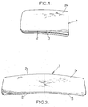
- the figure 1 represents a perspective view of a transfer board 1 for a person to facilitate its translation between two seated positions, preferably between a wheelchair and a car seat, the invention can of course be applied to any sitting position or any location on which a person may sit (such as a bed).
- the board 1 comprises at least two panels 2, 3 able to be articulated with respect to one another by means of a hinge forming an axis of rotation by hinges XX, so that one of the panels 2, 3 can be folded on the other of the panels 2, 3, thus facilitating its transport.
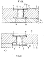
- the hinge XX constituted using at least one hinge (of known type), thus makes it possible to form a first folded position of the board 1 and a second completely unfolded or extended position of the board 1 (the board 1 then being substantially planar, see figure 2 ).
- Each panel 2, 3 has an upper face 2a, 3a and a lower face 2b, 3b. It is understood by “upper” face the face of the transfer board 1 on which is preferably able to slip the person during his passage from one location to another.
- This so-called upper face 2a is preferably smooth, substantially planar, and made of a material facilitating sliding, that is to say with a low coefficient of friction.
- FIG. 2 He is represented more precisely on the figure 2 an upper view of the transfer board 1 in its extended or fully unfolded position, that is to say in a view on the upper faces 2a, 3a of the panels 2, 3 of Plate 1.
- the Figures 5 to 7 represent, in turn, a perspective view of the lower faces 2b, 3b of the panels 2, 3 of the board 1 on which are provided means 5 for strengthening the joint XX.
- the means 5 for reinforcing the joint XX are in the form of at least one movable element 6, 7 extending, in fully unfolded position of the board 1, on either side of the axis of rotation.
- the board 1 in order to lighten the weight of the transfer board 1 and since the load of the person moving on the board 1 is mainly distributed on the reinforcing means 5, the board 1 can be made entirely of lightweight materials, such as only wood.
- the element 6, 7 is able to move by sliding between a position wherein the element 6, 7 is integrally housed in a complementary housing 6a, 7a formed in only one of the panels 2, 3 of the plate 1, and a position in which the element extends on both sides of the the axis of rotation XX in the two panels 2, 3.
- element 6, 7 is preferably in the form of a bar slider on which is fixed a projection 8 (for example by gluing or screwing) adapted to bear on at least one stop 9, 10 provided on the path of movement of the element 6, 7, so as to limit the displacement by sliding of this element 6, 7.
- the size and position of the projection 8 on the element 6, 7 is compatible with the location that can occupy the element 6, 7 in the respectively folded and extended positions of the board 1.
- the element 6, 7 may be of any shape (flat, H, 1 ). However, the most optimized form from the mechanical point of view is the I-section (eg IPN type metal profiles). On the other hand, a shape of the I-rail makes it possible to guarantee a higher security for the user during handling operations; there is indeed a lower probability of jamming his finger in the rail 11, 12, in which the element 6, 7 slides respectively.
- the projection 8 allows the user to manually move the element 6, 7 of reinforcement in the rail 11, 12, especially in case of inadvertent blocking.
- the shape of the projection 8 is preferably in a form adapted to a hand having little grip such as a quadriplegic hand.
- An anti-slip can also advantageously cover the projection 8 to facilitate gripping.
- the element 6, 7 is made rigid, that is to say it can be in the form of a metal bar, so as to stiffen the internal structure of the transfer board 1 in its extended position and thus achieve a strengthening structure of the joint XX when the board 1 is in its extended position (or fully unfolded) so that when a person slides on the upper face 2a, 3a of panels 2, 3 of the board 1, it is obtained a distribution of the forces exerted on the articulation XX at the level of this element 6, 7, so that the weight of the person is not only reflected on this joint XX but is also, or even essentially, spread over this or these elements 6,7.
- At least one rail 11, 12 is hollowed out in the lower surface 2b, 3b of the panels 2, 3 in which a respective element 6, 7 is slidably movable, the rail 11, 12 also forming the housing. 6a, 7a in which is housed the element 6, 7 in the folded position of the board 1.
- the transfer board 1 has two stops 9, 10 for limiting the displacement of the elements 6, 7 between the position allowing the folding and in which the elements 6, 7 are integrated in the panel 2 and do not exceed dimensions of this panel 2 (see figure 5 ), and a position in which the elements 6, 7 are located on either side of the hinge XX (see figure 7 ).
- the stops 9, 10 are in the form of a transverse bar fixed on the lower surface 2b, 3b of the panels 2, 3 forming a bridge through the rails 11,12 of the elements 6, 7.
- the projections 8 are then provided to abut against these bridges overhanging and crossing the rails 11, 12.
- the panels 2, 3 are of the same dimensions and are substantially symmetrical about the axis XX in the extended position of the boards 2, 3, that is to say in the substantially horizontal position, so that in folding position of a panel 2, 3 on the other panel 2, 3, then the bridge forming a stop 9 of one of the panels 2 is then in contact directly from the other abutment bridge 10 of the other of the panels 3. It is thus preferentially provided a stop 9, 10 on each panel 2, 3 on either side of the hinge XX.
- the element 6, 7 is limited in its displacement in the folded position of the board 1 by a flexible band 13 fixed in the rail 11, 12 of the element 6, 7 respectively on both sides of the joint XX, thanks to which the element 6, 7 is held inside its respective rail 11, 12 in the folded position of the board 1.
- the length and the stowage of the band 13 is set in such a way that it allows free movement of the element 6, 7 between the two extreme positions of the element 6, 7, that is to say between the position of the element 6, 7 in the housing 6a, 7a ( corresponding here to a part of the rail 11, 12) allowing the folding of the board 1 and the position of reinforcing the joint XX.
- this band 13 is not fixed or glued on any the length in the rail 11,12 but is simply fixed at specific points and limited in the rail 11, 12.
- the strip 13 is fixed only at its two ends inside the rail 11, 12.
- the locking means may thus be in the form of a latch adapted to cooperate with a recess formed in the projection 8 of the element 6, 7, this latch can be provided at the level of the folding position of the board 1, or at the position of reinforcing the joint XX so as to prevent its lateral sliding if the board is not substantially horizontal, that is to say at a placement transfer board 1 between two seated positions that are not at the same height.
- FIGS. 8 and 9 are two sectional views of a preferred embodiment of the locking means 14 in position of the element 6, 7 respectively in an inactive position and in an active position.
- the locking means 14 may be in the form of a displaceable projection 15 provided on the path of movement of the element 6, 7 between a position retracted inside the panel 2, 3 ( figure 8 ) and a protruding position ( figure 9 ).
- the projection 15 is of the binding screw type, that is to say comprises a cylindrical central body 16 surrounded by a first transverse body 17 and a second transverse body 18.
- the transverse bodies 17, 18 are substantially planar bodies, it should be understood that it is also possible to realize convex transverse bodies, so that the first transverse body 17 is slightly protruding of the upper face 2a of the panel 2 or slightly tucked inside its respective housing 19.
- the second transverse body 18 it can be made in any suitable form, not just planar, so that it allows a blocking when it protrudes out of the lower face 2b of the panel 2 and a free passage of the element 6, 7 in its respective rail 11, 12 when it is in a retracted position in its respective housing 20.
- the projection 15 is advantageously placed in the rail 11, 12 at a location such that the projection 15 allows the locking in the reinforcing position of the element 6, 7 on both sides of the hinge XX while having the protrusion 8 of the element 6, 7 in contact on the stop 10 provided on the other panel 3 opposite the panel 2 in which the projection 15 is placed.
- the board 1 can be provided on the board 1 handles formed in the panels 2, 3 from through recesses made at the edge of the edges of the panels 2, 3, so that the user can insert his hands to the interior of these recesses, which allows him to better handle the board 1 and to have a better seat and a better stability during its transfer by sliding on the board 1.
- the fields of the board 1 can be covered with a polymer strip for damping shocks.
- protections for example visible, such as a transparent thin plate of plexiglass type (registered trademark)
- These protections are made in such a way that they prevent the user from getting their fingers caught in the rails 11, 12, while allowing access to the projections 8 provided on the elements 6, 7 reinforcement in case of inadvertent blocking (the user can in this case manually unlock the element 6, 7).
Landscapes
- Health & Medical Sciences (AREA)
- Veterinary Medicine (AREA)
- Life Sciences & Earth Sciences (AREA)
- Animal Behavior & Ethology (AREA)
- General Health & Medical Sciences (AREA)
- Public Health (AREA)
- Nursing (AREA)
- Steps, Ramps, And Handrails (AREA)
- Special Chairs (AREA)
- Invalid Beds And Related Equipment (AREA)
- Fittings On The Vehicle Exterior For Carrying Loads, And Devices For Holding Or Mounting Articles (AREA)
- Motorcycle And Bicycle Frame (AREA)
- Devices For Medical Bathing And Washing (AREA)
- Laminated Bodies (AREA)
- Mattresses And Other Support Structures For Chairs And Beds (AREA)
Claims (8)
- Umlagerungsbrett (1) für eine Person, das es ermöglicht, deren Übergang zwischen zwei Sitzplätzen zu erleichtern, wobei das Brett (1) mindestens zwei Platten (2, 3) enthält, die mit Hilfe eines Gelenks (X-X), das eine Scharnier-Drehachse bildet, derart aneinander angelenkt werden können, dass eine der Platten (2, 3) sich auf die andere der Platten (2, 3) umklappen kann, wodurch eine zusammengeklappte Stellung des Bretts (1) definiert wird, wobei sich Verstärkungseinrichtungen (5) des Gelenks (X-X) in Form mindestens eines beweglichen Elements (6, 7) in der gestreckten oder vollständig auseinandergeklappten Stellung des Bretts (1) zu beiden Seiten der Scharnier-Drehachse (X-X) in den zwei Platten (2, 3) erstrecken, wodurch die Last der Person, die sich auf dem Umlagerungsbrett (1) in ausgestreckter Stellung verschiebt, sowohl auf das Gelenk (X-X) als auch auf das Element (6, 7) verteilt werden kann, wobei mindestens eine Schiene (11, 12) in den Platten (2, 3) ausgehöhlt ist, in der sich das Element (6, 7) verschieben kann, dadurch gekennzeichnet, dass ein elastisches Band (13) in der Schiene (11, 12) des Elements (6, 7) zu beiden Seiten des Gelenks (X-X) befestigt ist, wodurch das Element (6, 7) in der zusammengeklappten Stellung des Bretts (1) im Inneren seiner jeweiligen Schiene (11, 12) gehalten wird.
- Umlagerungsbrett nach Anspruch 1, dadurch gekennzeichnet, dass das Element (6, 7) sich durch Gleiten verschieben kann zwischen:- einer Stellung, in der das Element (6, 7) vollständig in einer komplementären Aufnahme (6a, 7a) angeordnet ist, die nur in einer der Platten (2, 3) des Bretts (1) geformt ist, und- einer Verstärkungsstellung, in der das Element (6, 7) sich zu beiden Seiten der Drehachse (X-X) in den zwei Platten (2, 3) erstreckt.
- Umlagerungsbrett nach einem der vorhergehenden Ansprüche, dadurch gekennzeichnet, dass das Element (6, 7) einen Vorsprung (8) enthält, der gegen mindestens einen Anschlag (9, 10) in Kontakt kommen kann, der auf dem Verschiebeweg des Elements (6, 7) vorgesehen ist.
- Umlagerungsbrett nach Anspruch 3, dadurch gekennzeichnet, dass der Anschlag (9, 10) in Form einer die Schiene (11, 12) überquerenden Brücke vorliegt.
- Umlagerungsbrett nach einem der vorhergehenden Ansprüche, dadurch gekennzeichnet, dass das Element (6, 7) eine gleitende Stange ist.
- Umlagerungsbrett nach einem der vorhergehenden Ansprüche, dadurch gekennzeichnet, dass zwei zueinander im Wesentlichen parallele Gleitschienen (11, 12) vorgesehen sind, in denen jeweils zwei Elemente (6, 7) vorgesehen sind, die sich verschieben können und deren Verschiebung durch mindestens einen Anschlag (9, 10) begrenzt wird.
- Umlagerungsbrett nach einem der vorhergehenden Ansprüche, dadurch gekennzeichnet, dass es Blockiereinrichtungen (14) der Verschiebung des Elements (6, 7) enthält, vorzugsweise in der Verstärkungsstellung des Gelenks (X-X).
- Umlagerungsbrett nach Anspruch 7, dadurch gekennzeichnet, dass die Blockiereinrichtungen (14) in Form eines verschiebbaren Vorsprungs (15) vorliegen, der auf dem Verschiebeweg des Elements (6, 7) zwischen einer ins Innere einer Platte (2, 3) zurückgezogenen Stellung und einer vorstehenden Stellung vorgesehen ist.
Priority Applications (1)
| Application Number | Priority Date | Filing Date | Title |
|---|---|---|---|
| PL08172953T PL2074977T3 (pl) | 2007-12-28 | 2008-12-26 | Deska transferowa dla jednej osoby, ułatwiająca jej przemieszczenie się między dwoma miejscami do siedzenia, zwłaszcza między wózkiem inwalidzkim a krzesłem |
Applications Claiming Priority (1)
| Application Number | Priority Date | Filing Date | Title |
|---|---|---|---|
| FR0760427A FR2925843B1 (fr) | 2007-12-28 | 2007-12-28 | Planche de transfert pour une personne permettant de faciliter sa translation entre deux emplacements assis, notamment entre un fauteuil roulant et un siege |
Publications (2)
| Publication Number | Publication Date |
|---|---|
| EP2074977A1 EP2074977A1 (de) | 2009-07-01 |
| EP2074977B1 true EP2074977B1 (de) | 2011-03-23 |
Family
ID=39689100
Family Applications (1)
| Application Number | Title | Priority Date | Filing Date |
|---|---|---|---|
| EP08172953A Not-in-force EP2074977B1 (de) | 2007-12-28 | 2008-12-26 | Transportbrett für eine Person zum leichteren Bewegen zwischen zwei Sitzgelegenheiten, insbesondere zwischen einem Rollstuhl und einem Stuhl |
Country Status (6)
| Country | Link |
|---|---|
| EP (1) | EP2074977B1 (de) |
| AT (1) | ATE502615T1 (de) |
| DE (1) | DE602008005698D1 (de) |
| ES (1) | ES2363184T3 (de) |
| FR (1) | FR2925843B1 (de) |
| PL (1) | PL2074977T3 (de) |
Families Citing this family (3)
| Publication number | Priority date | Publication date | Assignee | Title |
|---|---|---|---|---|
| US9629770B1 (en) * | 2011-12-19 | 2017-04-25 | Joseph T. Dyer | Portable transfer board and method |
| US20150190297A1 (en) * | 2014-01-07 | 2015-07-09 | Arun Rajagopal | Arm support apparatus for prone patients |
| CN115414214B (zh) * | 2022-09-06 | 2023-09-26 | 中国人民解放军总医院第五医学中心 | 一种多功能儿童用肝穿轮椅床 |
Family Cites Families (5)
| Publication number | Priority date | Publication date | Assignee | Title |
|---|---|---|---|---|
| US4700416A (en) * | 1986-02-18 | 1987-10-20 | Johansson Paul J | Patient transfer mat |
| JPH09234166A (ja) * | 1996-02-29 | 1997-09-09 | Toto Ltd | 浴室ユニット |
| CA2250548A1 (en) * | 1998-10-27 | 2000-04-27 | Antonio Ditommaso | Collapsible transfer bench |
| GB2387321B (en) * | 2002-04-10 | 2004-04-14 | Roozbeh Shirandami | Disabled transfer board |
| GB0417453D0 (en) | 2004-08-05 | 2004-09-08 | Mangar Int Ltd | Device for assisting disabled and elderly persons |
-
2007
- 2007-12-28 FR FR0760427A patent/FR2925843B1/fr not_active Expired - Fee Related
-
2008
- 2008-12-26 EP EP08172953A patent/EP2074977B1/de not_active Not-in-force
- 2008-12-26 ES ES08172953T patent/ES2363184T3/es active Active
- 2008-12-26 PL PL08172953T patent/PL2074977T3/pl unknown
- 2008-12-26 DE DE602008005698T patent/DE602008005698D1/de active Active
- 2008-12-26 AT AT08172953T patent/ATE502615T1/de not_active IP Right Cessation
Also Published As
| Publication number | Publication date |
|---|---|
| FR2925843A1 (fr) | 2009-07-03 |
| DE602008005698D1 (de) | 2011-05-05 |
| PL2074977T3 (pl) | 2011-09-30 |
| ATE502615T1 (de) | 2011-04-15 |
| FR2925843B1 (fr) | 2011-01-14 |
| EP2074977A1 (de) | 2009-07-01 |
| ES2363184T3 (es) | 2011-07-26 |
Similar Documents
| Publication | Publication Date | Title |
|---|---|---|
| FR2920209A1 (fr) | Crochet de suspension de poids | |
| FR2972990A1 (fr) | Chassis de poussette pour enfant a deux positions pliees, et poussette correspondante | |
| FR2635670A1 (fr) | Dispositif pour fixer provisoirement une canne a un support | |
| FR3023160A1 (fr) | Fauteuil articule comprenant un mecanisme de verticalisation pour un vehicule roulant. | |
| FR3021853A1 (fr) | Ensemble roulant modulable et transformable | |
| EP2074977B1 (de) | Transportbrett für eine Person zum leichteren Bewegen zwischen zwei Sitzgelegenheiten, insbesondere zwischen einem Rollstuhl und einem Stuhl | |
| FR2972989A1 (fr) | Poussette pour enfant a deux positions pliees, et chassis correspondant | |
| EP0279753A1 (de) | Konferenzgestell | |
| EP3141152B1 (de) | Zusammenklappbare konpakte tisch, besonders für schienenfahrzeug | |
| FR2732938A1 (fr) | Combinaison d'un chariot et d'un element amovible et element amovible pour chariot | |
| FR3054519A1 (fr) | Vehicule a roues depliable / repliable, notamment de type trottinette | |
| CA1279959C (fr) | Canape covertible en lit | |
| EP2178735B1 (de) | Umrüstbarer hängematten-kinderwagen und entsprechende hängematte | |
| FR2991252A1 (fr) | Plage arriere de vehicule a encombrement reduit | |
| EP3398808B1 (de) | Drehsitz mit hochklappbarer fussstütze, insbesondere für schienenfahrzeug | |
| FR2834431A1 (fr) | Valise equipee d'un siege | |
| FR2948265A1 (fr) | Bagage a main remorquable comprenant un systeme de soutien | |
| WO1994020309A1 (fr) | Support adaptable pour liste d'achats | |
| FR2984815A1 (fr) | Table a battants escamotables | |
| EP1679018B1 (de) | Tischplatte | |
| FR2948559A1 (fr) | Fauteuil roulant pliable | |
| FR2762978A1 (fr) | Table basse multi-usages pliante a position variable | |
| EP0808593A2 (de) | Hochstuhl mit verschiedenen Konfigurationen | |
| EP0986978A1 (de) | In ein Bett umwandelbares Sofa | |
| EP1942770B1 (de) | Gepäckverdeckender doppelsitz |
Legal Events
| Date | Code | Title | Description |
|---|---|---|---|
| PUAI | Public reference made under article 153(3) epc to a published international application that has entered the european phase |
Free format text: ORIGINAL CODE: 0009012 |
|
| AK | Designated contracting states |
Kind code of ref document: A1 Designated state(s): AT BE BG CH CY CZ DE DK EE ES FI FR GB GR HR HU IE IS IT LI LT LU LV MC MT NL NO PL PT RO SE SI SK TR |
|
| AX | Request for extension of the european patent |
Extension state: AL BA MK RS |
|
| 17P | Request for examination filed |
Effective date: 20091027 |
|
| AKX | Designation fees paid |
Designated state(s): AT BE BG CH CY CZ DE DK EE ES FI FR GB GR HR HU IE IS IT LI LT LU LV MC MT NL NO PL PT RO SE SI SK TR |
|
| GRAP | Despatch of communication of intention to grant a patent |
Free format text: ORIGINAL CODE: EPIDOSNIGR1 |
|
| GRAS | Grant fee paid |
Free format text: ORIGINAL CODE: EPIDOSNIGR3 |
|
| GRAA | (expected) grant |
Free format text: ORIGINAL CODE: 0009210 |
|
| AK | Designated contracting states |
Kind code of ref document: B1 Designated state(s): AT BE BG CH CY CZ DE DK EE ES FI FR GB GR HR HU IE IS IT LI LT LU LV MC MT NL NO PL PT RO SE SI SK TR |
|
| REG | Reference to a national code |
Ref country code: GB Ref legal event code: FG4D Free format text: NOT ENGLISH |
|
| REG | Reference to a national code |
Ref country code: CH Ref legal event code: EP |
|
| REG | Reference to a national code |
Ref country code: IE Ref legal event code: FG4D |
|
| REF | Corresponds to: |
Ref document number: 602008005698 Country of ref document: DE Date of ref document: 20110505 Kind code of ref document: P |
|
| REG | Reference to a national code |
Ref country code: DE Ref legal event code: R096 Ref document number: 602008005698 Country of ref document: DE Effective date: 20110505 |
|
| REG | Reference to a national code |
Ref country code: NL Ref legal event code: VDEP Effective date: 20110323 |
|
| REG | Reference to a national code |
Ref country code: ES Ref legal event code: FG2A Ref document number: 2363184 Country of ref document: ES Kind code of ref document: T3 Effective date: 20110726 |
|
| PG25 | Lapsed in a contracting state [announced via postgrant information from national office to epo] |
Ref country code: LT Free format text: LAPSE BECAUSE OF FAILURE TO SUBMIT A TRANSLATION OF THE DESCRIPTION OR TO PAY THE FEE WITHIN THE PRESCRIBED TIME-LIMIT Effective date: 20110323 Ref country code: SE Free format text: LAPSE BECAUSE OF FAILURE TO SUBMIT A TRANSLATION OF THE DESCRIPTION OR TO PAY THE FEE WITHIN THE PRESCRIBED TIME-LIMIT Effective date: 20110323 Ref country code: HR Free format text: LAPSE BECAUSE OF FAILURE TO SUBMIT A TRANSLATION OF THE DESCRIPTION OR TO PAY THE FEE WITHIN THE PRESCRIBED TIME-LIMIT Effective date: 20110323 Ref country code: GR Free format text: LAPSE BECAUSE OF FAILURE TO SUBMIT A TRANSLATION OF THE DESCRIPTION OR TO PAY THE FEE WITHIN THE PRESCRIBED TIME-LIMIT Effective date: 20110624 Ref country code: LV Free format text: LAPSE BECAUSE OF FAILURE TO SUBMIT A TRANSLATION OF THE DESCRIPTION OR TO PAY THE FEE WITHIN THE PRESCRIBED TIME-LIMIT Effective date: 20110323 |
|
| LTIE | Lt: invalidation of european patent or patent extension |
Effective date: 20110323 |
|
| PG25 | Lapsed in a contracting state [announced via postgrant information from national office to epo] |
Ref country code: SI Free format text: LAPSE BECAUSE OF FAILURE TO SUBMIT A TRANSLATION OF THE DESCRIPTION OR TO PAY THE FEE WITHIN THE PRESCRIBED TIME-LIMIT Effective date: 20110323 Ref country code: NO Free format text: LAPSE BECAUSE OF FAILURE TO SUBMIT A TRANSLATION OF THE DESCRIPTION OR TO PAY THE FEE WITHIN THE PRESCRIBED TIME-LIMIT Effective date: 20110623 Ref country code: CY Free format text: LAPSE BECAUSE OF FAILURE TO SUBMIT A TRANSLATION OF THE DESCRIPTION OR TO PAY THE FEE WITHIN THE PRESCRIBED TIME-LIMIT Effective date: 20110323 Ref country code: BG Free format text: LAPSE BECAUSE OF FAILURE TO SUBMIT A TRANSLATION OF THE DESCRIPTION OR TO PAY THE FEE WITHIN THE PRESCRIBED TIME-LIMIT Effective date: 20110623 Ref country code: AT Free format text: LAPSE BECAUSE OF FAILURE TO SUBMIT A TRANSLATION OF THE DESCRIPTION OR TO PAY THE FEE WITHIN THE PRESCRIBED TIME-LIMIT Effective date: 20110323 Ref country code: FI Free format text: LAPSE BECAUSE OF FAILURE TO SUBMIT A TRANSLATION OF THE DESCRIPTION OR TO PAY THE FEE WITHIN THE PRESCRIBED TIME-LIMIT Effective date: 20110323 |
|
| REG | Reference to a national code |
Ref country code: PL Ref legal event code: T3 |
|
| REG | Reference to a national code |
Ref country code: IE Ref legal event code: FD4D |
|
| PG25 | Lapsed in a contracting state [announced via postgrant information from national office to epo] |
Ref country code: PT Free format text: LAPSE BECAUSE OF FAILURE TO SUBMIT A TRANSLATION OF THE DESCRIPTION OR TO PAY THE FEE WITHIN THE PRESCRIBED TIME-LIMIT Effective date: 20110725 Ref country code: EE Free format text: LAPSE BECAUSE OF FAILURE TO SUBMIT A TRANSLATION OF THE DESCRIPTION OR TO PAY THE FEE WITHIN THE PRESCRIBED TIME-LIMIT Effective date: 20110323 |
|
| PG25 | Lapsed in a contracting state [announced via postgrant information from national office to epo] |
Ref country code: RO Free format text: LAPSE BECAUSE OF FAILURE TO SUBMIT A TRANSLATION OF THE DESCRIPTION OR TO PAY THE FEE WITHIN THE PRESCRIBED TIME-LIMIT Effective date: 20110323 Ref country code: IS Free format text: LAPSE BECAUSE OF FAILURE TO SUBMIT A TRANSLATION OF THE DESCRIPTION OR TO PAY THE FEE WITHIN THE PRESCRIBED TIME-LIMIT Effective date: 20110723 Ref country code: SK Free format text: LAPSE BECAUSE OF FAILURE TO SUBMIT A TRANSLATION OF THE DESCRIPTION OR TO PAY THE FEE WITHIN THE PRESCRIBED TIME-LIMIT Effective date: 20110323 Ref country code: CZ Free format text: LAPSE BECAUSE OF FAILURE TO SUBMIT A TRANSLATION OF THE DESCRIPTION OR TO PAY THE FEE WITHIN THE PRESCRIBED TIME-LIMIT Effective date: 20110323 |
|
| PG25 | Lapsed in a contracting state [announced via postgrant information from national office to epo] |
Ref country code: NL Free format text: LAPSE BECAUSE OF FAILURE TO SUBMIT A TRANSLATION OF THE DESCRIPTION OR TO PAY THE FEE WITHIN THE PRESCRIBED TIME-LIMIT Effective date: 20110323 |
|
| PLBE | No opposition filed within time limit |
Free format text: ORIGINAL CODE: 0009261 |
|
| STAA | Information on the status of an ep patent application or granted ep patent |
Free format text: STATUS: NO OPPOSITION FILED WITHIN TIME LIMIT |
|
| PG25 | Lapsed in a contracting state [announced via postgrant information from national office to epo] |
Ref country code: IE Free format text: LAPSE BECAUSE OF FAILURE TO SUBMIT A TRANSLATION OF THE DESCRIPTION OR TO PAY THE FEE WITHIN THE PRESCRIBED TIME-LIMIT Effective date: 20110323 |
|
| 26N | No opposition filed |
Effective date: 20111227 |
|
| PG25 | Lapsed in a contracting state [announced via postgrant information from national office to epo] |
Ref country code: DK Free format text: LAPSE BECAUSE OF FAILURE TO SUBMIT A TRANSLATION OF THE DESCRIPTION OR TO PAY THE FEE WITHIN THE PRESCRIBED TIME-LIMIT Effective date: 20110323 |
|
| REG | Reference to a national code |
Ref country code: DE Ref legal event code: R097 Ref document number: 602008005698 Country of ref document: DE Effective date: 20111227 |
|
| PG25 | Lapsed in a contracting state [announced via postgrant information from national office to epo] |
Ref country code: MC Free format text: LAPSE BECAUSE OF NON-PAYMENT OF DUE FEES Effective date: 20111231 |
|
| REG | Reference to a national code |
Ref country code: DE Ref legal event code: R119 Ref document number: 602008005698 Country of ref document: DE Effective date: 20120703 |
|
| PG25 | Lapsed in a contracting state [announced via postgrant information from national office to epo] |
Ref country code: DE Free format text: LAPSE BECAUSE OF NON-PAYMENT OF DUE FEES Effective date: 20120703 |
|
| PG25 | Lapsed in a contracting state [announced via postgrant information from national office to epo] |
Ref country code: MT Free format text: LAPSE BECAUSE OF FAILURE TO SUBMIT A TRANSLATION OF THE DESCRIPTION OR TO PAY THE FEE WITHIN THE PRESCRIBED TIME-LIMIT Effective date: 20110323 |
|
| PG25 | Lapsed in a contracting state [announced via postgrant information from national office to epo] |
Ref country code: LU Free format text: LAPSE BECAUSE OF NON-PAYMENT OF DUE FEES Effective date: 20111226 |
|
| REG | Reference to a national code |
Ref country code: CH Ref legal event code: PL |
|
| PG25 | Lapsed in a contracting state [announced via postgrant information from national office to epo] |
Ref country code: TR Free format text: LAPSE BECAUSE OF FAILURE TO SUBMIT A TRANSLATION OF THE DESCRIPTION OR TO PAY THE FEE WITHIN THE PRESCRIBED TIME-LIMIT Effective date: 20110323 |
|
| PG25 | Lapsed in a contracting state [announced via postgrant information from national office to epo] |
Ref country code: HU Free format text: LAPSE BECAUSE OF FAILURE TO SUBMIT A TRANSLATION OF THE DESCRIPTION OR TO PAY THE FEE WITHIN THE PRESCRIBED TIME-LIMIT Effective date: 20110323 Ref country code: CH Free format text: LAPSE BECAUSE OF NON-PAYMENT OF DUE FEES Effective date: 20121231 Ref country code: LI Free format text: LAPSE BECAUSE OF NON-PAYMENT OF DUE FEES Effective date: 20121231 |
|
| REG | Reference to a national code |
Ref country code: FR Ref legal event code: PLFP Year of fee payment: 8 |
|
| REG | Reference to a national code |
Ref country code: FR Ref legal event code: PLFP Year of fee payment: 9 |
|
| REG | Reference to a national code |
Ref country code: FR Ref legal event code: PLFP Year of fee payment: 10 |
|
| PGFP | Annual fee paid to national office [announced via postgrant information from national office to epo] |
Ref country code: PL Payment date: 20201127 Year of fee payment: 13 |
|
| PGFP | Annual fee paid to national office [announced via postgrant information from national office to epo] |
Ref country code: ES Payment date: 20210107 Year of fee payment: 13 |
|
| PGFP | Annual fee paid to national office [announced via postgrant information from national office to epo] |
Ref country code: GB Payment date: 20221219 Year of fee payment: 15 Ref country code: FR Payment date: 20221121 Year of fee payment: 15 |
|
| REG | Reference to a national code |
Ref country code: ES Ref legal event code: FD2A Effective date: 20230302 |
|
| PG25 | Lapsed in a contracting state [announced via postgrant information from national office to epo] |
Ref country code: ES Free format text: LAPSE BECAUSE OF NON-PAYMENT OF DUE FEES Effective date: 20211227 |
|
| PG25 | Lapsed in a contracting state [announced via postgrant information from national office to epo] |
Ref country code: PL Free format text: LAPSE BECAUSE OF NON-PAYMENT OF DUE FEES Effective date: 20211226 |
|
| PGFP | Annual fee paid to national office [announced via postgrant information from national office to epo] |
Ref country code: IT Payment date: 20221209 Year of fee payment: 15 |
|
| P01 | Opt-out of the competence of the unified patent court (upc) registered |
Effective date: 20231024 |
|
| PGFP | Annual fee paid to national office [announced via postgrant information from national office to epo] |
Ref country code: BE Payment date: 20231212 Year of fee payment: 16 |
|
| GBPC | Gb: european patent ceased through non-payment of renewal fee |
Effective date: 20231226 |
|
| PG25 | Lapsed in a contracting state [announced via postgrant information from national office to epo] |
Ref country code: GB Free format text: LAPSE BECAUSE OF NON-PAYMENT OF DUE FEES Effective date: 20231226 |
|
| PG25 | Lapsed in a contracting state [announced via postgrant information from national office to epo] |
Ref country code: FR Free format text: LAPSE BECAUSE OF NON-PAYMENT OF DUE FEES Effective date: 20231231 |
|
| PG25 | Lapsed in a contracting state [announced via postgrant information from national office to epo] |
Ref country code: GB Free format text: LAPSE BECAUSE OF NON-PAYMENT OF DUE FEES Effective date: 20231226 Ref country code: FR Free format text: LAPSE BECAUSE OF NON-PAYMENT OF DUE FEES Effective date: 20231231 |
|
| PG25 | Lapsed in a contracting state [announced via postgrant information from national office to epo] |
Ref country code: IT Free format text: LAPSE BECAUSE OF NON-PAYMENT OF DUE FEES Effective date: 20231226 |
|
| REG | Reference to a national code |
Ref country code: BE Ref legal event code: MM Effective date: 20241231 |
|
| PG25 | Lapsed in a contracting state [announced via postgrant information from national office to epo] |
Ref country code: BE Free format text: LAPSE BECAUSE OF NON-PAYMENT OF DUE FEES Effective date: 20241231 |