EP2075113B1 - Procédé et dispositif de marquage d'élément de feuille de caoutchouc - Google Patents
Procédé et dispositif de marquage d'élément de feuille de caoutchouc Download PDFInfo
- Publication number
- EP2075113B1 EP2075113B1 EP09005082A EP09005082A EP2075113B1 EP 2075113 B1 EP2075113 B1 EP 2075113B1 EP 09005082 A EP09005082 A EP 09005082A EP 09005082 A EP09005082 A EP 09005082A EP 2075113 B1 EP2075113 B1 EP 2075113B1
- Authority
- EP
- European Patent Office
- Prior art keywords
- rubber sheet
- rubber
- pressing
- rotation
- long
- Prior art date
- Legal status (The legal status is an assumption and is not a legal conclusion. Google has not performed a legal analysis and makes no representation as to the accuracy of the status listed.)
- Expired - Lifetime
Links
- 229920001971 elastomer Polymers 0.000 title claims description 303
- 239000005060 rubber Substances 0.000 title claims description 303
- 238000000034 method Methods 0.000 title claims description 28
- 238000003825 pressing Methods 0.000 claims description 92
- 238000004804 winding Methods 0.000 claims description 21
- 238000005520 cutting process Methods 0.000 claims description 15
- 238000005096 rolling process Methods 0.000 claims description 14
- 230000001105 regulatory effect Effects 0.000 claims description 3
- 238000001179 sorption measurement Methods 0.000 claims description 3
- 238000004519 manufacturing process Methods 0.000 description 14
- 238000007493 shaping process Methods 0.000 description 9
- 238000010586 diagram Methods 0.000 description 8
- 230000015572 biosynthetic process Effects 0.000 description 2
- 230000001276 controlling effect Effects 0.000 description 2
- 238000006073 displacement reaction Methods 0.000 description 2
- 238000001125 extrusion Methods 0.000 description 2
- 230000037303 wrinkles Effects 0.000 description 2
- 241000842962 Apoda limacodes Species 0.000 description 1
- JOYRKODLDBILNP-UHFFFAOYSA-N Ethyl urethane Chemical compound CCOC(N)=O JOYRKODLDBILNP-UHFFFAOYSA-N 0.000 description 1
- 238000013459 approach Methods 0.000 description 1
- 239000011324 bead Substances 0.000 description 1
- 230000003247 decreasing effect Effects 0.000 description 1
- 238000009826 distribution Methods 0.000 description 1
- 239000000463 material Substances 0.000 description 1
- 238000004073 vulcanization Methods 0.000 description 1
Images





Classifications
-
- B—PERFORMING OPERATIONS; TRANSPORTING
- B60—VEHICLES IN GENERAL
- B60C—VEHICLE TYRES; TYRE INFLATION; TYRE CHANGING; CONNECTING VALVES TO INFLATABLE ELASTIC BODIES IN GENERAL; DEVICES OR ARRANGEMENTS RELATED TO TYRES
- B60C13/00—Tyre sidewalls; Protecting, decorating, marking, or the like, thereof
- B60C13/001—Decorating, marking or the like
-
- B—PERFORMING OPERATIONS; TRANSPORTING
- B29—WORKING OF PLASTICS; WORKING OF SUBSTANCES IN A PLASTIC STATE IN GENERAL
- B29C—SHAPING OR JOINING OF PLASTICS; SHAPING OF MATERIAL IN A PLASTIC STATE, NOT OTHERWISE PROVIDED FOR; AFTER-TREATMENT OF THE SHAPED PRODUCTS, e.g. REPAIRING
- B29C48/00—Extrusion moulding, i.e. expressing the moulding material through a die or nozzle which imparts the desired form; Apparatus therefor
- B29C48/03—Extrusion moulding, i.e. expressing the moulding material through a die or nozzle which imparts the desired form; Apparatus therefor characterised by the shape of the extruded material at extrusion
- B29C48/09—Articles with cross-sections having partially or fully enclosed cavities, e.g. pipes or channels
- B29C48/10—Articles with cross-sections having partially or fully enclosed cavities, e.g. pipes or channels flexible, e.g. blown foils
-
- B—PERFORMING OPERATIONS; TRANSPORTING
- B29—WORKING OF PLASTICS; WORKING OF SUBSTANCES IN A PLASTIC STATE IN GENERAL
- B29C—SHAPING OR JOINING OF PLASTICS; SHAPING OF MATERIAL IN A PLASTIC STATE, NOT OTHERWISE PROVIDED FOR; AFTER-TREATMENT OF THE SHAPED PRODUCTS, e.g. REPAIRING
- B29C48/00—Extrusion moulding, i.e. expressing the moulding material through a die or nozzle which imparts the desired form; Apparatus therefor
- B29C48/15—Extrusion moulding, i.e. expressing the moulding material through a die or nozzle which imparts the desired form; Apparatus therefor incorporating preformed parts or layers, e.g. extrusion moulding around inserts
- B29C48/154—Coating solid articles, i.e. non-hollow articles
- B29C48/155—Partial coating thereof
-
- B—PERFORMING OPERATIONS; TRANSPORTING
- B29—WORKING OF PLASTICS; WORKING OF SUBSTANCES IN A PLASTIC STATE IN GENERAL
- B29C—SHAPING OR JOINING OF PLASTICS; SHAPING OF MATERIAL IN A PLASTIC STATE, NOT OTHERWISE PROVIDED FOR; AFTER-TREATMENT OF THE SHAPED PRODUCTS, e.g. REPAIRING
- B29C48/00—Extrusion moulding, i.e. expressing the moulding material through a die or nozzle which imparts the desired form; Apparatus therefor
- B29C48/25—Component parts, details or accessories; Auxiliary operations
- B29C48/266—Means for allowing relative movements between the apparatus parts, e.g. for twisting the extruded article or for moving the die along a surface to be coated
-
- B—PERFORMING OPERATIONS; TRANSPORTING
- B29—WORKING OF PLASTICS; WORKING OF SUBSTANCES IN A PLASTIC STATE IN GENERAL
- B29C—SHAPING OR JOINING OF PLASTICS; SHAPING OF MATERIAL IN A PLASTIC STATE, NOT OTHERWISE PROVIDED FOR; AFTER-TREATMENT OF THE SHAPED PRODUCTS, e.g. REPAIRING
- B29C48/00—Extrusion moulding, i.e. expressing the moulding material through a die or nozzle which imparts the desired form; Apparatus therefor
- B29C48/25—Component parts, details or accessories; Auxiliary operations
- B29C48/30—Extrusion nozzles or dies
- B29C48/35—Extrusion nozzles or dies with rollers
-
- B—PERFORMING OPERATIONS; TRANSPORTING
- B29—WORKING OF PLASTICS; WORKING OF SUBSTANCES IN A PLASTIC STATE IN GENERAL
- B29D—PRODUCING PARTICULAR ARTICLES FROM PLASTICS OR FROM SUBSTANCES IN A PLASTIC STATE
- B29D30/00—Producing pneumatic or solid tyres or parts thereof
- B29D30/06—Pneumatic tyres or parts thereof (e.g. produced by casting, moulding, compression moulding, injection moulding, centrifugal casting)
- B29D30/72—Side-walls
-
- B—PERFORMING OPERATIONS; TRANSPORTING
- B60—VEHICLES IN GENERAL
- B60C—VEHICLE TYRES; TYRE INFLATION; TYRE CHANGING; CONNECTING VALVES TO INFLATABLE ELASTIC BODIES IN GENERAL; DEVICES OR ARRANGEMENTS RELATED TO TYRES
- B60C13/00—Tyre sidewalls; Protecting, decorating, marking, or the like, thereof
- B60C13/04—Tyre sidewalls; Protecting, decorating, marking, or the like, thereof having annular inlays or covers, e.g. white sidewalls
-
- B—PERFORMING OPERATIONS; TRANSPORTING
- B29—WORKING OF PLASTICS; WORKING OF SUBSTANCES IN A PLASTIC STATE IN GENERAL
- B29C—SHAPING OR JOINING OF PLASTICS; SHAPING OF MATERIAL IN A PLASTIC STATE, NOT OTHERWISE PROVIDED FOR; AFTER-TREATMENT OF THE SHAPED PRODUCTS, e.g. REPAIRING
- B29C48/00—Extrusion moulding, i.e. expressing the moulding material through a die or nozzle which imparts the desired form; Apparatus therefor
-
- B—PERFORMING OPERATIONS; TRANSPORTING
- B29—WORKING OF PLASTICS; WORKING OF SUBSTANCES IN A PLASTIC STATE IN GENERAL
- B29C—SHAPING OR JOINING OF PLASTICS; SHAPING OF MATERIAL IN A PLASTIC STATE, NOT OTHERWISE PROVIDED FOR; AFTER-TREATMENT OF THE SHAPED PRODUCTS, e.g. REPAIRING
- B29C48/00—Extrusion moulding, i.e. expressing the moulding material through a die or nozzle which imparts the desired form; Apparatus therefor
- B29C48/03—Extrusion moulding, i.e. expressing the moulding material through a die or nozzle which imparts the desired form; Apparatus therefor characterised by the shape of the extruded material at extrusion
- B29C48/131—Curved articles
-
- B—PERFORMING OPERATIONS; TRANSPORTING
- B29—WORKING OF PLASTICS; WORKING OF SUBSTANCES IN A PLASTIC STATE IN GENERAL
- B29D—PRODUCING PARTICULAR ARTICLES FROM PLASTICS OR FROM SUBSTANCES IN A PLASTIC STATE
- B29D30/00—Producing pneumatic or solid tyres or parts thereof
- B29D30/06—Pneumatic tyres or parts thereof (e.g. produced by casting, moulding, compression moulding, injection moulding, centrifugal casting)
- B29D30/72—Side-walls
- B29D2030/726—Decorating or marking the sidewalls before tyre vulcanization
-
- B—PERFORMING OPERATIONS; TRANSPORTING
- B29—WORKING OF PLASTICS; WORKING OF SUBSTANCES IN A PLASTIC STATE IN GENERAL
- B29K—INDEXING SCHEME ASSOCIATED WITH SUBCLASSES B29B, B29C OR B29D, RELATING TO MOULDING MATERIALS OR TO MATERIALS FOR MOULDS, REINFORCEMENTS, FILLERS OR PREFORMED PARTS, e.g. INSERTS
- B29K2021/00—Use of unspecified rubbers as moulding material
-
- B—PERFORMING OPERATIONS; TRANSPORTING
- B29—WORKING OF PLASTICS; WORKING OF SUBSTANCES IN A PLASTIC STATE IN GENERAL
- B29L—INDEXING SCHEME ASSOCIATED WITH SUBCLASS B29C, RELATING TO PARTICULAR ARTICLES
- B29L2030/00—Pneumatic or solid tyres or parts thereof
- B29L2030/007—Sidewalls
Definitions
- the present invention relates to a tire having characters or lines different in colour from the surroundings on a side wall part, and particularly to a method and an apparatus for pressing a rubber sheet member.
- a method for manufacturing a tire is known in which a green tire is shaped by stamping each of tire-constitutional members on the outside of a toroidal-shape carcass member fixed onto a rigid core or a shaping drum and vulcanizing it in order to make the shape of a product tire or dimensions of each of the members highly accurate.
- a rubber member among these tire-constitutional members is stamped by winding a continuous rubber ribbon in plural turns, and according to this manufacturing method, when compared with the case where a rubber having a cross section corresponding to a cross section of a member in the product tire is wound only once for formation, there is no need to extrude a rubber member with a large cross-section which can reduce the size of an extruder and moreover, by directly winding a rubber ribbon extruded from a smaller-sized extruder onto a toroidal-shape carcass member, the need of a large amount of an intermediate stock of members which has been necessary for production of other types of tires can be eliminated.
- members with different cross sections can be formed with a rubber ribbon in the same cross sectional shape only by changing the number of times or position of winding and green tires of different sizes can be formed continuously.
- the tire made of the rubber member formed by winding the rubber ribbon in plural turns in this way has high uniformity and tire balance, since there is no joint across the total width of each member.
- FIG. 1 is a perspective view showing a portion of a side wall part of a product tire on which the character "I" is formed in white, for example.
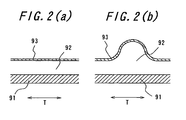
- FIG. 2 is a sectional view corresponding to II-II arrow view in FIG. 1 showing the state in the middle of manufacture of the tire portion where this character is formed
- FIGS. 3(a) and 3(b) are a sectional view and a perspective view showing the detail of this character portion in the product tire.
- B indicates a black rubber portion and W for a white rubber portion
- T is an arrow showing the circumferential direction of the tire.
- the a-a arrow view in FIG. 3(b) corresponds with the cross section of FIG. 3(a) .
- this white character As shown in FIG. 2(a) , at the stage to shape a green tire, after a black side wall rubber 92 is stamped on the outside of a carcass member 91 to be a base, a black cover rubber 93 is stamped on a side wall part on which the white character is to be expressed. And in vulcanizing this green tire, as shown in FIG. 2(b) , the white character portion is projected from the other portions using a mold with a recess portion corresponding to the white character.
- the projected portion is buffed to remove the cover rubber 93, and the white side wall rubber 92 appears from under it and the white character can be formed.
- the cover rubber 93 is formed by overlapping a narrow-width ribbon, as shown in FIG. 3(b) , a step between the ribbons appears on a cross section 93a in which the overlapping portion between the ribbons is buffed, which causes a problem on appearance. Even if the ribbon is wound so that a gap between the ribbons becomes zero in order to solve the problem, it is actually difficult to bring this gap to zero, and a gap or overlapping will occur and the problem on appearance has not been solved yet.
- the present invention has been made in view of the above problem and has an object to provide a tire having characters or lines different in colour from the surroundings on a side wall part, a manufacturing method in which a large extruder is not needed, wherein other types of tires can be efficiently manufactured since size switching is easy, the shape and the dimensions of the members are highly accurate, the uniformity and the tire balance are excellent, and a tire with sharp profiles of characters or lines and having good appearance can be obtained, and in particular to provide a method and an apparatus for pressing a rubber sheet member.
- the present invention provides a method of pressing a rubber sheet member in the annular state on a side face of a body of rotation, wherein:
- the present invention further provides a method of pressing a rubber sheet member according to item (1), wherein in cutting the long rubber sheet extending on said tangent so as to form the leading end and the rear end of said rubber sheet, both the cut-off faces of the leading end and the rear end of the rubber sheet are inclined with respect to the width direction of the long sheet, and the long rubber sheet is cut off so that, in the cut-off face of the rubber sheet leading end, the end in the width direction to be the outside in the radial direction of the annular band is located closer to the front in the traveling direction of the long sheet than the end in the width direction to be the inside in the radial direction, while in the cut-off face of the rubber sheet rear end, the end in the width direction to be the outside in the radial direction on the annular band is located closer to the rear in the traveling direction of the long sheet than the end in the width direction to be the inside in the radial direction, and a rubber sheet portion in the shape of a trapezoid or a triangle defined by the cut-off face
- the present invention further provides a method of pressing a rubber sheet member on a side face of a body of rotation in the annular state, wherein:
- the present invention further provides a method of pressing a rubber sheet member according to item (3), wherein said gap is made uniform over the width direction so as to roll the rubber sheet.
- the present invention further provides a method of pressing a rubber sheet member according to item (3) or (4), wherein after the rolled rubber sheet is wound around one of the truncated conical rollers by a predetermined angle, the rubber sheet is transferred from this truncated conical roller to the body of rotation while pressing the wound rubber sheet onto the body of rotation.
- the present invention further provides a method of pressing a rubber sheet member according to item (3), (4) or (5) wherein the rubber sheet wound around said one of the truncated conical rollers is cut off in the width direction on this truncated conical roller.
- the present invention further provides a rubber sheet member pressing device used for the pressing method according to item (1) or (2), comprising:
- the present invention further provides a rubber sheet member pressing device according to item (7), wherein said leading-end holding part is to hold the rubber sheet leading end by vacuum adsorption.
- the present invention further provides a rubber sheet member pressing device according to item (7) or (8), wherein double blades inclined in the reverse orientation from each other with respect to the face crossing the long rubber sheet delivery direction are disposed on said cutter, and anvils for receiving these blades and a cutter displacing means for displacing the cutter in the direction crossing the rubber sheet face arranged on the anvil are provided, and a gap for removing a trapezoidal or triangular rubber sheet portion left after cutting by the double blades is arranged between these anvils.
- the present invention further provides a rubber sheet member pressing device used for the pressing method according to any one of items (3) to (6), comprising:
- the present invention further provides a rubber sheet member pressing device according to item (10), wherein said rolling machine is provided between the pair of truncated conical rollers with almost a uniform gap over the width direction therebetween.
- the present invention further provides a rubber sheet member pressing device according to item (10) or (11), wherein the large-diameter side of one of the truncated conical rollers is arranged opposite to the outside in the radial direction of the side face of the body of rotation and the small-diameter side of this roller to the inside in the radial direction of the side face of the body of rotation in the winding posture of the rubber sheet onto the body of rotation.
- the present invention further provides a rubber sheet member pressing device according to any one of items (10) to (12), wherein an opening of the die of the extruder is a slit whose width is gradually increased from one end to the other end, and the wide side end of the opening is arranged corresponding to the large diameter side of the truncated conical roller and the narrow side end of the opening corresponding to the small diameter side of the truncated conical roller.
- FIG. 1 is a perspective view showing a character portion expressed on the surface of a product tire.
- FIGS. 2(a) and 2(b) are sectional views showing the state in the middle of manufacture of the character portion, respectively.
- FIGS. 3(a) and 3(b) are a sectional view and a perspective view showing the detail of the character portion in the prior art, respectively.
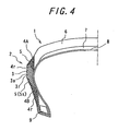
- FIG. 4 is a sectional view showing a quarter part of a tire on the meridional cross-section.
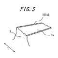
- FIG. 5 is a perspective view showing a detailed portion of a part of the ' character.
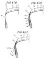
- FIGS. 6(a) to 6(c) are meridional cross sectional views of a green tire for explaining the process for shaping a green tire by pressing a side wall rubber, respectively.
- FIG. 7 is a perspective view showing a method of forming a side wall rubber by winding a rubber ribbon.
- FIGS. 8(a) and 8(b) are schematic diagrams showing a side face of a green tire being shaped, respectively.
- FIGS. 9a and 9b are schematic diagrams showing a side face of a green tire in the process subsequent to FIGS. 8(a) and 8(b) , respectively.
- FIG. 10 is a front view showing an overlapping portion between a leading end and a rear end of a rubber sheet.
- FIG. 11 is a perspective view showing a cut-off portion of a long sheet.
- FIG. 12 is a front view showing an overlapping portion between a leading end and a rear end of a rubber sheet.
- FIG. 13 is a partial schematic sectional view of a cover rubber pressing device used for the pressing method according to the invention shown on the face in parallel with a central axis of rotation of a carcass member.
- FIG. 14 is a diagram for explaining operation of a cover rubber pressing device.
- FIGS. 15(a) and 15(b) are diagrams for explaining operation of a cover rubber pressing device subsequent to FIG.. 14 .
- FIG. 16 is a perspective view showing another embodiment of a cover rubber pressing device used for the pressing method according to the present invention.
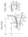
- FIGS. 17(a) and 17(b) are partial sectional views showing relative arrangement of a rolling machine and a carcass member.
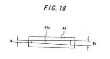
- FIG. 18 is a front view showing an opening of a die.
- FIGS. 19(a) to 19(d) are diagrams for explaining a method of pressing a rubber sheet onto an annular band.
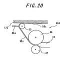
- FIG. 20 is a partial sectional view showing a cover rubber pressing device provided with exclusive pressing rollers.
- FIG. 4 is a meridional cross sectional view showing a cross section of a half on which characters or lines in colour different from the surroundings are provided among halves divided by the equatorial cross section in a tire of a preferred embodiment according to the present invention.
- a side wall 2 arranged on one side in the axial direction of a carcass 8 is comprised of a first colour side wall rubber 3 expressed as a character 3a, second colour side wall rubbers 4A and 4B located on both sides in the radial direction of the first colour side wall rubber 3, respectively, and a second colour cover rubber 5 covering the first colour side wall rubber 3 other than the character 3a;
- the first colour side wall rubber 3 and the second colour side wall rubbers 4A and 4B are made of a continuous first colour rubber ribbon 3r and a second colour rubber ribbon 4r wound in plural turns, respectively, and the cover rubber is made of a single thin annular rubber sheet 5s.
- the first colour is white, for example, while the second colour is black, for example.
- both boundary surfaces of the first colour side wall rubber 3 with the second colour side wall rubbers 4A and 4B are arranged inclined almost in parallel, but these boundary surfaces may be inclined in the reverse orientation from each other, and either of the radial extending width outside in the axial direction or the radial extending width inside in the axial direction of the first colour side wall rubber 3 can be larger, and moreover the second colour side wall rubbers 4A and 4B can be continuous inside in the axial direction of the first colour side wall rubber 3.
- the side wall which is not shown but arranged on the other side in the axial direction of the carcass 8 is comprised of the continuous second colour rubber ribbon 4r wound in plural turns in all the areas, and numeral 6 represents a tread, 8 is a belt and 9 is a bead core.
- the tread 6 is also made of a continuous rubber ribbon wound in plural turns.
- FIG. 5 is a perspective view showing a detailed portion of a part of the character 3a shown in correspondence with FIG. 3(b) , and since the cover rubber 5 is constituted by a single thin annular rubber sheet 5s, a zigzag-state step does not appear around the character 3a, and the profile of the character 3a extending in the direction crossing the tire circumferential direction T can be also expressed sharply.
- FIG. 6 is a meridional cross sectional yiew of a green tire for explaining a process to shape a green tire by pressing the side wall on the side having characters or lines.
- a carcass member 18 is toroidally formed on the outside of a shaping drum or a rigid core, not shown, and FIG. 6(a) shows the state where a belt member 17 and a tread rubber 18 have been already pressed outside in the radial direction on the so formed carcass member 18. After the state shown in FIG.
- a second colour side wall rubber 14A outside in the radial direction is pressed by winding a continuous second colour rubber ribbon 14r in plural turns, as shown in FIG. 6(b) .
- a first colour side wall rubber 13 is pressed by winding a continuous first colour rubber ribbon 13r in plural turns, and subsequently a second colour side wall rubber 14B inside in the radial direction is pressed by winding a continuous second colour rubber ribbon 14r in plural turns.
- a cover rubber 15 is pressed outside these side wall rubbers 13, 14A and 14B by winding a rubber sheet 15s annularly in one turn so as to shape the green tire 10.
- the order of pressing the side wall rubbers 13, 14A and 14B can be determined as appropriate depending on how to laminate the rubber ribbons.
- the green tire 10 is removed from the shaping drum and transferred to a vulcanizing machine, while if the green tire 10 is formed on a rigid core, the green tire 10 is not removed from the rigid core but transferred to the vulcanizing machine together with the rigid core so as to vulcanize the green tire 10 by the vulcanizing machine.
- the side wall rubbers 13, 14A and 14B can be pressed by a known method of winding the rubber ribbon, and FIG. 7 shows one example.
- the leading end of the second colour rubber ribbon 14r is pressed and then, while controlling the position of the second colour rubber ribbon 14r in the radial direction and moving a pressing roller 61 for pressing this onto the side face of the carcass member 18, the shaping drum is rotated in the R direction in plural turns so as to press the second color side wall rubber 14A.
- the second colour rubber ribbon 14r is extruded through an extruder 62 synchronously with the winding by the amount by which the second colour rubber ribbon 14r is wound.
- a festoon 63 By providing a festoon 63, unbalance between the winding amount and the extrusion amount of the second colour rubber ribbon 14r can be adjusted.
- the extruder 62 can be made small-sized, one type of the rubber ribbon 14r can form rubber members in various sectional shapes, and moreover size can be switched only by choosing a trajectory program for displacing the pressing roller 61 from those stored in advance in correspondence with each size and by calling and starting it, by which instantaneous size switching is enabled and manufacturing of small amounts in other types can be realized efficiently.
- FIGS. 8 and 9 are schematic diagrams showing the side face of a green tire in the middle of shaping, and in order to press the cover rubber 15, first, as shown in FIG. 8(a) , a leading end 15f of a long rubber sheet 15s arranged on a tangent G of an annular band 12a on the side wall rubber 12, to be the pressing face for the cover rubber 15, having been already pressed on the outside of the carcass member 18 is held, and then, as shown in FIG. 8(b) , this leading end 15f is moved onto the annular band 12a and pressed. As shown in FIG.
- the carcass member 18 is rotated around its central axis in the direction of the arrow R while applying a tension to the rubber sheet 15s so as to press the rubber sheet 15s on the annular band, and after the rotation of the carcass member 18 is stopped, as shown in FIG. 9(b) , an unpressed portion of the long rubber sheet 15s is cut off in the cut-off face C extending in the width direction of the long rubber sheet 15s. Next, the unpressed portion to be a rear end 15e of the rubber sheet wound in the annular state is pressed onto the annular band 12a to complete pressing of the cover rubber 15.
- FIG. 10 is a view of an overlapping portion between the leading end 15f and the rear end 15e of the rubber sheet 15s seen from the axial direction of the green tire 10 after the cover rubber 15 has been pressed, and an area A1 on the large arc side of the cover rubber 15 defined by a straight lines L1 and L2 extending in the radial direction from the central axis O of rotation of the carcass member 18 is an area pressed by rotation of the carcass member 18 and deformed into the arc state, while the leading end 15f defined by the straight line L1 and a starting end X1 is a non-deformed area required for holding.
- the leading end 15f forms a rectangle
- the rear end 15e defined by the straight line L2 and a terminating end X2 is also a non-deformed area required for cutting and forms a rectangle
- an inner width j2 in the radial direction is larger than an outer width j1 in the radial direction.
- FIG. 11 is a perspective view showing a cut-off portion of the long sheet for explaining a method to solve the above problem.
- a cut-off face Y1 of the rubber sheet leading end 15f and the cut-off face Y2 of the rear end 15e are both inclined with respect to the width direction of the long sheet 15s by angles ⁇ 1 and ⁇ 2, respectively, and in the cut-off face Y1 of the rubber sheet leading end 15f, a width-direction end PY1A on the side to be outside in the radial direction on the annular band 12a is located closer to the front in the long sheet traveling direction shown by an arrow D than a width-direction end PY1B on the side to be the inside in the radial direction, while in the cut-off face Y2 of the rubber sheet rear end 15e, a width-direction
- FIG. 12 is a view showing the overlapping portion between the leading end 15f and the rear end 15 when the rubber sheet 15s having been cut in this way is pressed on the annular band 12a, corresponding to FIG. 10 , and the area A1 on the large arc side of the cover rubber 15 defined by the straight lines L1 and L2 extending in the radial direction from the center of rotation O of the carcass member 18 is an area deformed in the arc state as in that shown in FIG. 10 .
- the leading end 15f defined by the straight line L1 and the starting end Y1 (that is, the cut-off face Y1 of the leading end 15f) is a non-deformed area, but L1 and X1 are mutually inclined by the angle ⁇ 1, while the rear end 15e defined by the straight line L2 and the terminating end X2 (that is, the cut-off face Y2 of the rear end 15e) is also a non-deformed area, but L2 and X2 are mutually inclined by the angle ⁇ 2, and unlike those shown in FIG. 10 , the starting end X1 and the terminating end X2 can be made almost in parallel.
- the inner width j2 in the radial direction and the outer width j1 in the radial direction can be minimized, whereby tire unbalance can be improved.
- FIG. 13 is a schematic partial sectional view of a cover rubber stamping device showing the state after the long rubber sheet 15s is cut in the plane in parallel with the central axis O of rotation of the carcass member 18 passing through the above tangent G.
- a cover rubber pressing device 20 is provided with a rubber sheet delivery means 21 for reeling the long rubber sheet 15s prepared by being wound around a reel, not shown, out of the reel for delivery, a tensioner 22 for applying a tension to the delivered long rubber sheet 15s, a leading end holding part 23 for holding the leading end 15f of the long rubber sheet, a leading-end holding part displacing means, not shown, for displacing this leading end holding part 23 back and forth between the holding start position and the holding end position, a pressing roller 24 for pressing the rubber sheet from the leading end 15f to the rear end 15e onto the annular band, a rubber sheet guide mechanism 25 for regulating an entry position of the long rubber sheet 15s into the annular band 12a, and a cutter 26 for forming the rubber sheet leading end 15f and the rear end 15e by cutting off said long sheet 15s.
- These means are fixed or mounted capable of relative displacement onto a support member 35.
- 12a indicates an annular band to be the pressing face for the rubber sheet 15s, and the arrow R shows its circumferential direction.
- LA indicates a straight line corresponding to the position of the starting end Y1 of the rubber sheet 15s to be wound.
- the leading end holding part 23 is constituted to hold the rubber sheet leading end 15f by vacuum adsorption, and by this, only one face of the leading end 15f is held with the other face brought into contact with the annular band 12a.
- the rubber sheet can be held at the very end, and the size of the leading end 15f to be the non-deformed area can be minimized.
- double blades 27A and 27B inclined in the reverse orientation from each other with respect to the face crossing the long rubber sheet delivery direction D are disposed on the cutter 26.
- the cover rubber pressing device 20 is provided with anvils 28A and 28B respectively receiving these blades 27A and 27B, and a cutter displacing means 29 for displacing the cutter in the direction D2 crossing the rubber sheet face arranged on the anvils 28A and 28B, and between these anvils 28A and 28B, a gap 31 for removing a trapezoidal or triangular rubber sheet portion AZ cut off by the double blades 27A and 27B is arranged.
- the cutter displacing means 29 is constituted by a simple air cylinder, but another driving mechanism can also be used. Also, by arranging a buffer 32 made of rubber or urethane, for example, at a portion located between the cutter displacing means 29 and the double blades 27A and 27B of the cutter 26, contact of the blades with the anvils 28A and 28B can be secured at any position.
- the rubber sheet delivery means 21 is constituted to be operated by holding the rubber sheet 15s between a pair of delivery rollers 21a and 21b and by driving these delivery rollers 21a and 21b by a motor, not shown, and by setting the delivery speed at this time smaller than the circumferential speed of the annular band 12a on the above tangent G, a tension in the middle of winding can be applied to the rubber sheet 15s so that generation of wrinkles on the cover rubber 15 can be prevented.
- the tensioner 22 is provided to completely prevent generation of wrinkles even at start and end of the winding.
- the tensioner 22 can be operated by pulling a tension roller 22a by a cylinder, not shown, and the tension is adjusted by adjusting the tensile force of the cylinder.
- the pressing roller 24 for pressing the rubber sheet 15s onto the annular band 12a is conical having a large diameter on the side opposite to the outside of the annular band 12a in the radial direction and a small diameter on the side opposite to the inside of the annular band 12a in the radial direction. By this, a slip rate between the rubber sheet 15s and the pressing roller 24 can be reduced almost to zero over the full length of the pressing roller 24.
- FIGS. 14 and 15 After the state shown in FIG. 13 , vacuum is activated to hold the rubber sheet leading end 15f with the leading end holding part 23, and the leading end holding part 23 is displaced to the state shown in FIG. 14 so that the starting end Y1 is located on the straight line LA. Next, from the shown state, the leading end holding part 23 is made closer to the annular band 12a, and then the vacuum is deactivated, the holding of the leading end 15f is released and the leading end 15f is transferred to the annular band 12a.
- the anvils 28A and 28B together with the support member 35 are separated away from the straight line LA, and the pressing roller 24 is also displaced in the direction opposite to the displacement direction of the anvils 28A and 28B.
- the leading end holding part 23 is lowered to press the portion to be the leading end 15f of the rubber sheet 15s, and the cutter 26 is lowered so as to cut off the rubber sheet 15s.
- the cut-off face Y1 of the leading end and the cut-off face Y2 of the rear end inclined opposite to each other with respect to the width direction of the rubber sheet is formed, and the rubber sheet portion AZ held between these cut-off faces is ejected through the gap 31 provided between the anvils 28A and 28B by operating an end rubber ejecting device, not shown.
- the carcass member 18 is rotated by a micro angle, and the rear end 15e of the rubber sheet, which is an unpressed portion, is wound while being pressed by the pressing roller 24 to complete the operation of one cycle.
- FIG. 16 is a perspective view showing a cover rubber pressing device for pressing the cover rubber 15 onto the annular band 12a of the side wall rubber 12 to be its pressing face.
- a cover rubber pressing device 40 is provided with a rolling machine 45 comprised of a large roller 46 and a small roller 47 constituting a pair of truncated conical rollers, an extruder 41 for extruding the rubber sheet into a gap formed between these rollers 46 and 47, and a cutter 48 for cutting a rolled rubber sheet 50s in the width direction on the large roller 46.
- the extruder 41 is provided with a gear pump part 43 for controlling an extrusion amount of the rubber sheet, a screw part 42 for plasticizing a rubber material and delivering it to the gear pump part 43, and a die 44 for specifying the sectional shape of the extruded rubber sheet.
- the rollers 46 and 47 of the rolling machine are driven by a motor and a chain, not shown, in synchronization with each other, and the cutter 48 can be brought closer to or separated from the large roller 46 by a cutter cylinder 49 at predetermined timing, and by this operation, a rubber sheet 50s on the large roller 46 can be cut off in the width direction.
- FIG. 17 is a view showing the relative positions of the rolling machine 45 and the carcass member 18 on which the side wall rubber 12 has been already pressed
- FIG. 17(a) is a partial sectional view in the meridional cross section of the carcass member 18
- FIG. 17(b) is a partial sectional view corresponding to the arrow view b-b of FIG. 17(a) .
- the rolling machine 45 is for pressing the rubber sheet 50s to be the cover rubber 15 on the annular band 12a of the side wall rubber 12, and the large roll 46 of the rolling machine 45 is arranged in contact with the annular band 12a through a slight gap, while the small roll 47 is provided on the side of the large roll 46 opposite to the carcass member 18 in contact with the large roll 46 through a gap g which is uniform in the width direction.
- the tip end of the die 44 is arranged closer to this gap, and the cutter 48 is provided on the large roll 46 capable of separating and approaching along its radial direction on the gap side opposite to the die 44 side.
- each of the outside and inside diameters of annular band 12a in the radial direction is set as D 0 and d 0
- the diameters of the large roll 46 at both end positions of the rubber sheet 50s in the width direction is set as D 1 on the large diameter side and d1 on the small diameter side.
- the diameters of the small roll 47 at both end positions of the rubber sheet 50s in the width direction are set as D 2 on the large diameter side and d 2 on the small diameter side. Then, a relationship represented by an equation (1) is established among these D 0 to D 2 and d 0 to d 2 .
- the rubber sheet portion to be the outer circumference of the cover rubber 15 in the radial direction and the rubber sheet portion to be the inner circumference in the radial direction is elongated at the same elongation rate, and by decreasing this elongation rate, a cover rubber 15 whose dimension is stable at any portion can be formed.
- FIG. 18 is a front view showing an opening 44a of the die 44.
- This opening 44a is a slit, and when the opening width of one end is W 1 and the opening width of the other end is W 2 , W 1 and W 2 is in the relation satisfying an equation (2), and the width of the intermediate portion of the opening 44a is set so that it is linearly increased from one end to the other end.
- the die 44 is arranged so that one end to be the narrow-side end of the opening 44a corresponds with the small diameter side of the roller 46 or 47, while the other end to be the wide-side end of the opening 44a corresponds with the large diameter side of the roller 46 or 47, and by this, a flow rate of the rubber passing through the wide-side end of the opening 44a is made larger than the flow rate of the rubber passing the narrow-side end so that a uniform elongation rate and thickness can be secured from the outside in the radial direction with longer circumferential length to the inside in the radial direction with shorter circumferential length of the cover rubber 15.
- the width change between both ends of the opening 44a is made linear, but this can be non-linear according to the desirable thickness distribution of the cover rubber to be pressed in the annular state.
- FIG. 19 is an explanatory diagram explaining a method of pressing the rubber sheet 50s on the annular band 12a using this cover rubber pressing device 40 and shows with the section corresponding to FIG. 17(b) .
- FIG. 19(a) is a diagram showing the state immediately before beginning to wind the rubber sheet 50s, in which the tip end of the rubber sheet 50s is held on the circumference of the large roller 46 and the large roller 46 is stopped at the rotational position where the tip end of the rubber sheet 50s is the closest to the annular band 12a. After this state, the large roller 46 and the small roller 47 are made closer to the annular band 12a as shown by the arrow, and the tip end of the rubber sheet 50s is pressed onto the annular band 12a. Next, as shown in FIG.
- FIG. 20 is a partial sectional view showing a cover rubber stamping device 40A provided with this exclusive pressing roller 53 shown on the section corresponding to FIG. 17(b) .
- the rubber sheet 50s rolled between the truncated conical large roller 46 and the small roller 47 is wound around the exclusive pressing roller 53 and pressed between the exclusive pressing roller 53 and the annular band 12a at the same time so that the cover rubber 15 can be stamped.
- a cutter 48a for processing the leading end and the rear end of the rubber sheet 50s is provided for cutting off the rubber sheet 50s on the exclusive pressing roller 53.
- this is not limited to pressing of the cover rubber but can be also applied to a side face of a general body of rotation, for example where a rubber sheet is wound around a side face of a tire in one turn to form various types of annular rubber members.
Landscapes
- Engineering & Computer Science (AREA)
- Mechanical Engineering (AREA)
- Manufacturing & Machinery (AREA)
- Tyre Moulding (AREA)
- Extrusion Moulding Of Plastics Or The Like (AREA)
- Heating, Cooling, Or Curing Plastics Or The Like In General (AREA)
- Moulds For Moulding Plastics Or The Like (AREA)
Claims (13)
- Procédé de pression d'un élément de feuille de caoutchouc dans l'état annulaire sur une face latérale d'un corps rotatif, dans lequel :une extrémité avant (15f) d'une longue feuille de caoutchouc (15s) agencée sur une tangente (G) d'une bande annulaire (12a) sur la face latérale du corps rotatif, constituant une face de pression de l'élément de feuille de caoutchouc, est retenue, l'extrémité avant (12f) étant transférée sur la bande annulaire (12a) et pressée, la feuille de caoutchouc (15s) étant ensuite pressée sur la bande annulaire (12a) par suite de la rotation du corps rotatif sur son axe central, tout en appliquant une tension à cette feuille de caoutchouc (15s), après l'arrêt de la rotation du corps rotatif, une partie non pressée de la longue feuille de caoutchouc (15s) estdécoupée, et la partie non pressée, constituant l'extrémité arrière (15e) de la feuille de caoutchouc sur la bande annulaire, est pressée sur la bande annulaire pour exercer une pression sur l'élément de feuille de caoutchouc.
- Procédé de pression d'un élément de feuille de caoutchouc selon la revendication 1, dans lequel , lors du découpage de la longue feuille de caoutchouc (15s), s'étendant sur ladite tangente (G), de sorte à former l'extrémité avant (15f) et l'extrémité arrière (15e) de ladite feuille de caoutchouc, les deux faces découpées (Y1, Y2) de l'extrémité avant (15f) et de l'extrémité arrière (15e) de la feuille de caoutchouc sont inclinées par rapport à la direction de la largeur de la longue feuille, la longue feuille de caoutchouc (15s) étant découpée, de sorte que dans la face découpée (Y1) de l'extrémité avant de la feuille de caoutchouc (15f), l'extrémité dans la direction de la largeur (PY1A), constituant l'extrémité externe dans la direction radiale dans de la bande annulaire (12a) est agencée plus près de l'avant dans la direction de déplacement (D) de la longueur feuille que l'extrémité dans la direction de la largeur (PY1B), constituantle côté interne dans la direction radiale, tandis que dans la face découpée (Y2) de l'extrémité arrière (15e) de la feuille de caoutchouc, l'extrémité dans la direction de la largeur (PY2A), constituant le côté externe dans la direction radiale de la bande annulaire (12a), est agencée plus près de l'arrière dans la direction du déplacement (D) de la longue feuille que l'extrémité dans la direction de la largeur (PY2B), constituant le côtéinterne dans la direction radiale ; et
une partie de la feuille de caoutchouc (AZ), de forme trapézoïdale ou triangulaire, définie par la face découpée (Y2) de l'extrémité arrière (15e) de la feuille de caoutchouc pressée en premier lieu, et la face découpée (Y1) de l'extrémité avant (15f) de la feuille de caoutchouc, devant être pressée ensuite, est enlevée. - Procédé de pression d'un élément de feuille de caoutchouc dans l'état annulaire sur une face latérale d'un corps rotatif, dans lequel :une feuille de caoutchouc (50s), extrudée à travers une filière (44) est passée à travers un espace (g) formé en agençant de manière mutuellement opposée les côtés à grand diamètre et les côtés à diamètre réduit d'une paire de rouleaux coniques tronqués (46, 47) en vue du laminage, et immédiatement après le laminage de cette feuille de caoutchouc (50s), la feuille de caoutchouc est pressée dans l'état annulaire, de sorte que le côté de la feuille de caoutchouc laminé par le côté à grand diamètre du rouleau conique tronqué correspond au côté externe dans la direction radiale de la face latérale du corps rotatif, le côté laminé par le côté à diamètre réduit du rouleau conique tronqué correspondant au côté interne dans la direction radiale de la face latérale du corps rotatif.
- Procédé de pression d'un élément de feuille de caoutchouc selon la revendication 3, dans lequel ledit espace (g) est uniformisé sur la direction de la largeur, de sorte à laminer la feuille de caoutchouc (50s).
- Procédé de pression d'un élément de feuille de caoutchouc selon les revendications 3 ou 4, dans lequel, après l'enroulement de la feuille de caoutchouc laminée (50s) autour de l'un des rouleaux coniques tronqués (46), à un angle prédéterminé, la feuille de caoutchouc est transférée du rouleau conique tronqué (46) vers le corps rotatif, tout en pressant la feuille de caoutchouc enroulée (50s) sur le corps rotatif.
- Procédé de pression d'un élément de feuille de caoutchouc selon l'une quelconque des revendications 3 à 5, dans lequel la feuille de caoutchouc (50s) enroulée autour dudit un rouleau des rouleaux coniques tronqués (46) est découpée dans la direction de la largeur sur le rouleau conique tronqué (46).
- Dispositif de pression d'un élément de feuille de caoutchouc, utilisé pour le procédé de pression selon les revendications 1 ou 2, comprenant :un moyen d'amenée de la feuille de caoutchouc (21), pour amener ladite longue feuille de caoutchouc (15s), un dispositif de tension (22) pour appliquer une tension à la longue feuille de caoutchouc amenée (15s), une partie de retenue de l'extrémité avant (23) pour retenir l'extrémité avant (15f) de la longue feuille de caoutchouc (15s), un moyen de déplacement de la partie de retenue de l'extrémité avant, pour déplacer la partie de retenue de l'extrémité avant (23) vers l'arrière et vers l'avant entre une position d'initialisation de la retenue et une position d'arrêt de la retenue, un rouleau de pression (24) pour presser la feuille de caoutchouc à travers l'extrémité avant (15f) vers l'extrémité arrière (15e) sur ladite bande annulaire (12a), un mécanisme de guidage de la feuille de caoutchouc (25), pour régler une position d'entrée de la longue feuille de caoutchouc (15s) dans la bande annulaire (12a), et un dispositif de coupe (26) pour former l'extrémité avant (15f) et l'extrémité arrière (15e) de la feuille de caoutchouc en découpant ladite longue feuille (15s).
- Dispositif de pression d'un élément de feuille de caoutchouc selon la revendication 7, dans lequel ladite partie de retenue de l'extrémité avant (23) est adaptée pour retenir l'extrémité avant de la feuille de caoutchouc (15f) par absorption à vide.
- Dispositif depression d'une feuille de caoutchouc selon les revendications 7 ou 8, dans lequel des doubles lames (27A, 27B), inclinées dans une orientation mutuellement inverse par rapport à la face croisant la direction d'amenée de la longue feuille de caoutchouc (D), sont agencées sur ledit dispositif de coupe (26), et comportant des enclumes (28A, 28B) pour recevoir les lames (27A, 27B) et un moyen de déplacement du dispositif de coupe (29), pour déplacer le dispositif de coupe dans la direction (D2) croisant la face de la feuille de caoutchouc agencée sur l'enclume (28A, 28B), un espace (31) pour retirer une partie trapézoïdale ou triangulaire de la feuille de caoutchouc (AZ) restante après le découpage par les doubles lames (27A, 27B) étant agencé entre les enclumes (28A, 28B).
- Dispositif de pression d'un élément de feuille de caoutchouc, utilisé pour le procédé de pression selon les revendications 3 à 6, comprenant :une extrudeuse (41), pour extruder une feuille de caoutchouc (50s) à travers une filière (44), une machine de laminage (45) comprenant une paire de rouleaux coniques tronqués (46, 47), agencés de sorte que leurs côtés à grand diamètre et les côtés à diamètre réduit correspondent les uns aux autres, et un dispositif de coupe (48) pour découper la feuille de caoutchouc dans la direction de la largeur.
- Dispositif de pression d'un élément de feuille de caoutchouc selon la revendication 10, dans lequel ladite machine de laminage (45) est agencée entre la paire de rouleaux coniques tronqués (46, 47), un espace pratiquement uniforme (s) s'étendant sur la direction de la largeur étant agencé entre eux.
- Dispositif de pression d'un élément de feuille de caoutchouc selon les revendications 10 ou 11, dans lequel le côté à grand diamètre de l'un des rouleaux coniques tronqués (46) est agencé en un emplacement opposé au côté externe dans la direction radiale de la face latérale du corps rotatif, le côté à diamètre réduit du rouleau (46) étant agencé vers l'intérieur dans la direction radiale de la face latérale du corps rotatif, dans l'état d'enroulement de la feuille de caoutchouc (50s) sur le corps rotatif.
- Dispositif de pression d'un élément de feuille de caoutchouc selon l'une quelconque des revendications 10 à 12, dans lequel une ouverture (44a) de la filière (44) de l'extrudeuse (41) est constituée par une fente, dont la largeur est progressivement accrue d'une extrémité vers l'autre extrémité, l'extrémité du côté large de l'ouverture étant agencé de manière correspondante au côté à grand diamètre du rouleau conique tronqué (46), et l'extrémité du côté étroit de l'ouverture étant agencé de manière correspondante au côté à diamètre réduit du rouleau conique tronqué (46).
Applications Claiming Priority (2)
| Application Number | Priority Date | Filing Date | Title |
|---|---|---|---|
| JP2002308695 | 2002-10-23 | ||
| EP03758827A EP1555114B1 (fr) | 2002-10-23 | 2003-10-23 | Procede de fabrication de pneus, dispositif de pression d'une couverture en caoutchouc adapte pour la realisation de ce procede de fabrication et pneumatique |
Related Parent Applications (2)
| Application Number | Title | Priority Date | Filing Date |
|---|---|---|---|
| EP03758827.4 Division | 2003-10-23 | ||
| EP03758827A Division EP1555114B1 (fr) | 2002-10-23 | 2003-10-23 | Procede de fabrication de pneus, dispositif de pression d'une couverture en caoutchouc adapte pour la realisation de ce procede de fabrication et pneumatique |
Publications (2)
| Publication Number | Publication Date |
|---|---|
| EP2075113A1 EP2075113A1 (fr) | 2009-07-01 |
| EP2075113B1 true EP2075113B1 (fr) | 2012-07-18 |
Family
ID=32170985
Family Applications (2)
| Application Number | Title | Priority Date | Filing Date |
|---|---|---|---|
| EP09005082A Expired - Lifetime EP2075113B1 (fr) | 2002-10-23 | 2003-10-23 | Procédé et dispositif de marquage d'élément de feuille de caoutchouc |
| EP03758827A Expired - Lifetime EP1555114B1 (fr) | 2002-10-23 | 2003-10-23 | Procede de fabrication de pneus, dispositif de pression d'une couverture en caoutchouc adapte pour la realisation de ce procede de fabrication et pneumatique |
Family Applications After (1)
| Application Number | Title | Priority Date | Filing Date |
|---|---|---|---|
| EP03758827A Expired - Lifetime EP1555114B1 (fr) | 2002-10-23 | 2003-10-23 | Procede de fabrication de pneus, dispositif de pression d'une couverture en caoutchouc adapte pour la realisation de ce procede de fabrication et pneumatique |
Country Status (7)
| Country | Link |
|---|---|
| US (1) | US7622013B2 (fr) |
| EP (2) | EP2075113B1 (fr) |
| JP (1) | JP4603890B2 (fr) |
| CN (1) | CN1713981B (fr) |
| DE (1) | DE60327705D1 (fr) |
| ES (2) | ES2325208T3 (fr) |
| WO (1) | WO2004037524A1 (fr) |
Families Citing this family (22)
| Publication number | Priority date | Publication date | Assignee | Title |
|---|---|---|---|---|
| US7364635B2 (en) * | 2004-04-27 | 2008-04-29 | Toyo Tire & Rubber Co., Ltd. | Manufacturing method of pneumatic tire |
| JP4718215B2 (ja) * | 2004-04-27 | 2011-07-06 | 東洋ゴム工業株式会社 | 空気入りタイヤの製造方法 |
| JP4551447B2 (ja) * | 2004-05-10 | 2010-09-29 | ピレリ・タイヤ・ソチエタ・ペル・アツィオーニ | タイヤ製造方法 |
| WO2006049222A1 (fr) * | 2004-11-04 | 2006-05-11 | Bridgestone Corporation | Procede de production de pneu |
| JP4748653B2 (ja) | 2005-05-16 | 2011-08-17 | 東洋ゴム工業株式会社 | 空気入りタイヤの製造方法 |
| JP4912645B2 (ja) * | 2005-09-06 | 2012-04-11 | 東洋ゴム工業株式会社 | 空気入りタイヤ |
| JP2008213750A (ja) * | 2007-03-07 | 2008-09-18 | Bridgestone Corp | 空気入りタイヤ及び空気入りタイヤの製造方法 |
| EP2296867B1 (fr) | 2008-04-23 | 2015-05-27 | MICHELIN Recherche et Technique S.A. | Procédé de formation d'un composant multicouche pour pneumatique |
| JP5117340B2 (ja) * | 2008-09-25 | 2013-01-16 | 東洋ゴム工業株式会社 | 空気入りタイヤの製造方法 |
| KR101014308B1 (ko) | 2008-12-02 | 2011-02-16 | 한국타이어 주식회사 | 자동차용 타이어 제조 방법 |
| EP2365904B1 (fr) | 2008-12-05 | 2014-02-12 | MICHELIN Recherche et Technique S.A. | Procédé et appareil permettant de former un composant de pneumatique sur une surface conique axialement |
| JP5081265B2 (ja) * | 2010-03-09 | 2012-11-28 | 住友ゴム工業株式会社 | タイヤ用ゴム部材の製造方法、及びそれに用いる製造装置 |
| JP5675403B2 (ja) * | 2011-02-08 | 2015-02-25 | 株式会社ブリヂストン | タイヤの製造方法 |
| DE102011001657A1 (de) * | 2011-03-30 | 2012-10-04 | Continental Reifen Deutschland Gmbh | Fahrzeugluftreifen |
| US20150013871A1 (en) * | 2013-07-15 | 2015-01-15 | Bridgestone Americas Tire Operations, Llc | Compression Molded Green Rubber Component and Method for Manufacturing the Same |
| JP6523763B2 (ja) * | 2015-04-17 | 2019-06-05 | 住友ゴム工業株式会社 | 空気入りタイヤの製造方法 |
| CN106042790B (zh) * | 2016-07-14 | 2018-02-09 | 赛轮金宇集团股份有限公司 | 超低断面彩色轮胎及其生产方法 |
| FR3060459A1 (fr) * | 2016-12-20 | 2018-06-22 | Compagnie Generale Des Etablissements Michelin | Pneumatique resistant aux attaques chimiques |
| CN107672200A (zh) * | 2017-09-07 | 2018-02-09 | 特拓(青岛)轮胎技术有限公司 | 一种用于轮胎径向力偏差修理的方法 |
| CN112703381B (zh) * | 2018-09-13 | 2023-11-21 | 米其林集团总公司 | 自动采样系统和方法 |
| IT202100032090A1 (it) | 2021-12-22 | 2023-06-22 | Pirelli | Processo ed apparato di etichettatura di uno pneumatico crudo per biciclette |
| CN114103208A (zh) * | 2021-12-24 | 2022-03-01 | 山东丰源轮胎制造股份有限公司 | 一种白胎侧结构及贴合激光定位装置 |
Family Cites Families (20)
| Publication number | Priority date | Publication date | Assignee | Title |
|---|---|---|---|---|
| US2769123A (en) * | 1952-12-12 | 1956-10-30 | Westinghouse Electric Corp | Servo system, including ward-leonard controlled servomotor |
| GB1017464A (en) | 1961-12-28 | 1966-01-19 | Dunlop Rubber Co | Improvements in or relating to pneumatic tyres and to methods of their manufacture |
| US3769123A (en) * | 1971-03-24 | 1973-10-30 | Goodyear Tire & Rubber | Method of making non-cracking decorative sidewalls of tires |
| SE404896B (sv) | 1977-04-05 | 1978-11-06 | Stabil Mek Verk | Anordning for paleggning av ett bandformigt material pa sidorna till en rotationssymmetrisk kropp |
| US4177233A (en) * | 1978-04-25 | 1979-12-04 | The Firestone Tire & Rubber Company | Method for forming side-wall strip in a tube |
| FR2603841B1 (fr) * | 1986-09-17 | 1989-02-24 | Michelin & Cie | Procede de fabrication d'un pneumatique avec pose des produits caoutchouteux et des elements de renforcement sur un support, dispositif de pose des produits caoutchouteux et machine qui utilise de tel(s) dispositif(s) |
| US4768939A (en) * | 1987-11-17 | 1988-09-06 | Monsanto Company | Apparatus for forming shaped interlayer blanks |
| DE3815542A1 (de) * | 1988-05-06 | 1989-11-16 | Stahlgruber Gruber & Co Otto | Geraet fuer das aufbringen von zierringen auf rotationssymmetrische gummigegenstaende, insbesondere die sichtbare oberflaeche von fahrzeugreifen |
| JPH04275136A (ja) * | 1991-02-28 | 1992-09-30 | Sumitomo Rubber Ind Ltd | 空気入りタイヤの製造方法 |
| JP3072921B2 (ja) | 1991-07-04 | 2000-08-07 | 住友ゴム工業株式会社 | 空気入りタイヤ |
| JPH091694A (ja) * | 1995-06-21 | 1997-01-07 | Bridgestone Corp | 空気入りタイヤのサイドウォールのライン形成方法 |
| JPH09254274A (ja) * | 1996-03-21 | 1997-09-30 | Bridgestone Corp | 更生用グリーンタイヤの製造方法及び装置 |
| JP3310901B2 (ja) | 1997-04-21 | 2002-08-05 | 住友ゴム工業株式会社 | ビードエイペックスジョイント装置 |
| JP2001179849A (ja) * | 1999-12-28 | 2001-07-03 | Bridgestone Corp | 空気入りタイヤの製造装置及び製造方法 |
| JP3774107B2 (ja) * | 2000-06-07 | 2006-05-10 | 住友ゴム工業株式会社 | 空気入りタイヤ |
| JP3566915B2 (ja) * | 2000-09-07 | 2004-09-15 | 住友ゴム工業株式会社 | タイヤ用ゴム部材の製造方法 |
| JP4160245B2 (ja) * | 2000-10-30 | 2008-10-01 | 住友ゴム工業株式会社 | 空気入りタイヤ及びその製造方法 |
| EP1201414B2 (fr) * | 2000-10-30 | 2019-12-04 | Sumitomo Rubber Industries, Ltd. | Procédé de fabrication d'un flanc de pneumatique |
| JP2002200677A (ja) | 2000-12-28 | 2002-07-16 | Bridgestone Corp | 空気入りタイヤの製造方法 |
| US20020088529A1 (en) * | 2000-11-22 | 2002-07-11 | Bridgestone Corporation | Method for manufacturing pneumatic tire |
-
2003
- 2003-10-23 EP EP09005082A patent/EP2075113B1/fr not_active Expired - Lifetime
- 2003-10-23 ES ES03758827T patent/ES2325208T3/es not_active Expired - Lifetime
- 2003-10-23 CN CN2003801040434A patent/CN1713981B/zh not_active Expired - Fee Related
- 2003-10-23 DE DE60327705T patent/DE60327705D1/de not_active Expired - Lifetime
- 2003-10-23 JP JP2004546462A patent/JP4603890B2/ja not_active Expired - Fee Related
- 2003-10-23 WO PCT/JP2003/013562 patent/WO2004037524A1/fr not_active Ceased
- 2003-10-23 EP EP03758827A patent/EP1555114B1/fr not_active Expired - Lifetime
- 2003-10-23 ES ES09005082T patent/ES2390532T3/es not_active Expired - Lifetime
- 2003-10-23 US US10/532,315 patent/US7622013B2/en not_active Expired - Fee Related
Also Published As
| Publication number | Publication date |
|---|---|
| EP1555114A4 (fr) | 2006-05-03 |
| ES2390532T3 (es) | 2012-11-13 |
| DE60327705D1 (de) | 2009-07-02 |
| EP2075113A1 (fr) | 2009-07-01 |
| CN1713981A (zh) | 2005-12-28 |
| JPWO2004037524A1 (ja) | 2006-02-23 |
| ES2325208T3 (es) | 2009-08-28 |
| US7622013B2 (en) | 2009-11-24 |
| JP4603890B2 (ja) | 2010-12-22 |
| CN1713981B (zh) | 2010-05-05 |
| US20060048878A1 (en) | 2006-03-09 |
| EP1555114B1 (fr) | 2009-05-20 |
| WO2004037524A1 (fr) | 2004-05-06 |
| EP1555114A1 (fr) | 2005-07-20 |
Similar Documents
| Publication | Publication Date | Title |
|---|---|---|
| EP1555114B1 (fr) | Procede de fabrication de pneus, dispositif de pression d'une couverture en caoutchouc adapte pour la realisation de ce procede de fabrication et pneumatique | |
| EP0899080B1 (fr) | Procédé et dispositif pour la fabrication d' éléments de remplissage pour talons de pneumatique | |
| EP0873852A2 (fr) | Procédé de confection de pneus crus | |
| EP0139604A2 (fr) | Appareil et procédé de fabrication d'une bande en rubans | |
| JP2008044354A (ja) | カーカス補強プライを張り付ける装置及び方法 | |
| US4283241A (en) | Method of producing a tire for a pneumatic tire arrangement | |
| JP2000289122A (ja) | トレッド成型方法 | |
| JP2001145960A (ja) | タイヤカーカスの形成装置および形成方法 | |
| EP2151314B1 (fr) | Procédé de production d'un élément en caoutchouc pour pneu et procédé de fabrication d'un pneu | |
| JP6644626B2 (ja) | ビードコア被覆方法及びビードコア被覆装置 | |
| JP6916063B2 (ja) | 空気入りタイヤの製造方法及び装置 | |
| EP2301738B1 (fr) | Dispositif de formage et procédé de formage d un élément en caoutchouc | |
| EP1279485B1 (fr) | Procédé de fabrication de peumatique contenant une couche renforcée par des cordes | |
| EP1555113A1 (fr) | Procede et appareil de formation d'une couche de renforcement de fils cables pour pneu | |
| JP2004167900A (ja) | コード入りタイヤ構成部材の形成方法 | |
| JP7138079B2 (ja) | ビードコア被覆方法及びビードコア被覆装置 | |
| JP4402415B2 (ja) | タイヤ用コード補強層の形成方法およびコード補強層形成装置 | |
| EP2191985A1 (fr) | Pneumatique, appareil et procede de moulage d'un pneumatique | |
| JP2009126143A (ja) | ストリップゴム連続成型設備及びストリップゴム連続成型方法 | |
| JP5041929B2 (ja) | 円環状ゴム部材の製造方法 | |
| JP7096091B2 (ja) | 空気入りタイヤの製造方法及び装置 | |
| JP4904049B2 (ja) | 空気入りタイヤの製造方法 | |
| JPH028029A (ja) | 合成樹脂螺旋管の製造装置 | |
| JP3442018B2 (ja) | カーカス層の形成方法およびタイヤの製造方法 | |
| JP2012166468A (ja) | タイヤ成型方法及びタイヤ成型装置 |
Legal Events
| Date | Code | Title | Description |
|---|---|---|---|
| PUAI | Public reference made under article 153(3) epc to a published international application that has entered the european phase |
Free format text: ORIGINAL CODE: 0009012 |
|
| 17P | Request for examination filed |
Effective date: 20090415 |
|
| AC | Divisional application: reference to earlier application |
Ref document number: 1555114 Country of ref document: EP Kind code of ref document: P |
|
| AK | Designated contracting states |
Kind code of ref document: A1 Designated state(s): DE ES FR GB IT |
|
| 17Q | First examination report despatched |
Effective date: 20100115 |
|
| GRAP | Despatch of communication of intention to grant a patent |
Free format text: ORIGINAL CODE: EPIDOSNIGR1 |
|
| RIC1 | Information provided on ipc code assigned before grant |
Ipc: B60C 13/00 20060101ALI20120104BHEP Ipc: B29C 47/32 20060101ALI20120104BHEP Ipc: B60C 13/04 20060101ALI20120104BHEP Ipc: B29D 30/72 20060101AFI20120104BHEP |
|
| GRAS | Grant fee paid |
Free format text: ORIGINAL CODE: EPIDOSNIGR3 |
|
| GRAA | (expected) grant |
Free format text: ORIGINAL CODE: 0009210 |
|
| AC | Divisional application: reference to earlier application |
Ref document number: 1555114 Country of ref document: EP Kind code of ref document: P |
|
| AK | Designated contracting states |
Kind code of ref document: B1 Designated state(s): DE ES FR GB IT |
|
| REG | Reference to a national code |
Ref country code: GB Ref legal event code: FG4D |
|
| REG | Reference to a national code |
Ref country code: DE Ref legal event code: R096 Ref document number: 60341586 Country of ref document: DE Effective date: 20120906 |
|
| REG | Reference to a national code |
Ref country code: ES Ref legal event code: FG2A Ref document number: 2390532 Country of ref document: ES Kind code of ref document: T3 Effective date: 20121113 |
|
| PLBE | No opposition filed within time limit |
Free format text: ORIGINAL CODE: 0009261 |
|
| STAA | Information on the status of an ep patent application or granted ep patent |
Free format text: STATUS: NO OPPOSITION FILED WITHIN TIME LIMIT |
|
| 26N | No opposition filed |
Effective date: 20130419 |
|
| REG | Reference to a national code |
Ref country code: DE Ref legal event code: R097 Ref document number: 60341586 Country of ref document: DE Effective date: 20130419 |
|
| REG | Reference to a national code |
Ref country code: FR Ref legal event code: CA Effective date: 20140812 |
|
| REG | Reference to a national code |
Ref country code: FR Ref legal event code: PLFP Year of fee payment: 13 |
|
| REG | Reference to a national code |
Ref country code: FR Ref legal event code: PLFP Year of fee payment: 14 |
|
| REG | Reference to a national code |
Ref country code: FR Ref legal event code: PLFP Year of fee payment: 15 |
|
| PGFP | Annual fee paid to national office [announced via postgrant information from national office to epo] |
Ref country code: FR Payment date: 20171024 Year of fee payment: 15 Ref country code: DE Payment date: 20171019 Year of fee payment: 15 |
|
| PGFP | Annual fee paid to national office [announced via postgrant information from national office to epo] |
Ref country code: GB Payment date: 20171019 Year of fee payment: 15 Ref country code: IT Payment date: 20171023 Year of fee payment: 15 Ref country code: ES Payment date: 20171121 Year of fee payment: 15 |
|
| REG | Reference to a national code |
Ref country code: DE Ref legal event code: R119 Ref document number: 60341586 Country of ref document: DE |
|
| GBPC | Gb: european patent ceased through non-payment of renewal fee |
Effective date: 20181023 |
|
| PG25 | Lapsed in a contracting state [announced via postgrant information from national office to epo] |
Ref country code: DE Free format text: LAPSE BECAUSE OF NON-PAYMENT OF DUE FEES Effective date: 20190501 |
|
| PG25 | Lapsed in a contracting state [announced via postgrant information from national office to epo] |
Ref country code: FR Free format text: LAPSE BECAUSE OF NON-PAYMENT OF DUE FEES Effective date: 20181031 |
|
| PG25 | Lapsed in a contracting state [announced via postgrant information from national office to epo] |
Ref country code: IT Free format text: LAPSE BECAUSE OF NON-PAYMENT OF DUE FEES Effective date: 20181023 Ref country code: GB Free format text: LAPSE BECAUSE OF NON-PAYMENT OF DUE FEES Effective date: 20181023 |
|
| REG | Reference to a national code |
Ref country code: ES Ref legal event code: FD2A Effective date: 20191203 |
|
| PG25 | Lapsed in a contracting state [announced via postgrant information from national office to epo] |
Ref country code: ES Free format text: LAPSE BECAUSE OF NON-PAYMENT OF DUE FEES Effective date: 20181024 |