EP2075170B1 - Fahrassistenzsystem für ein Fahrzeug das auf einem Weg ohne Fahrspurabgrenzungslinien fährt - Google Patents
Fahrassistenzsystem für ein Fahrzeug das auf einem Weg ohne Fahrspurabgrenzungslinien fährt Download PDFInfo
- Publication number
- EP2075170B1 EP2075170B1 EP07425834A EP07425834A EP2075170B1 EP 2075170 B1 EP2075170 B1 EP 2075170B1 EP 07425834 A EP07425834 A EP 07425834A EP 07425834 A EP07425834 A EP 07425834A EP 2075170 B1 EP2075170 B1 EP 2075170B1
- Authority
- EP
- European Patent Office
- Prior art keywords
- roadway
- vehicle
- lane
- npixel
- control means
- Prior art date
- Legal status (The legal status is an assumption and is not a legal conclusion. Google has not performed a legal analysis and makes no representation as to the accuracy of the status listed.)
- Active
Links
Images


Classifications
-
- B—PERFORMING OPERATIONS; TRANSPORTING
- B60—VEHICLES IN GENERAL
- B60W—CONJOINT CONTROL OF VEHICLE SUB-UNITS OF DIFFERENT TYPE OR DIFFERENT FUNCTION; CONTROL SYSTEMS SPECIALLY ADAPTED FOR HYBRID VEHICLES; ROAD VEHICLE DRIVE CONTROL SYSTEMS FOR PURPOSES NOT RELATED TO THE CONTROL OF A PARTICULAR SUB-UNIT
- B60W50/00—Details of control systems for road vehicle drive control not related to the control of a particular sub-unit, e.g. process diagnostic or vehicle driver interfaces
- B60W50/08—Interaction between the driver and the control system
- B60W50/14—Means for informing the driver, warning the driver or prompting a driver intervention
-
- G—PHYSICS
- G06—COMPUTING OR CALCULATING; COUNTING
- G06V—IMAGE OR VIDEO RECOGNITION OR UNDERSTANDING
- G06V20/00—Scenes; Scene-specific elements
- G06V20/50—Context or environment of the image
- G06V20/56—Context or environment of the image exterior to a vehicle by using sensors mounted on the vehicle
- G06V20/588—Recognition of the road, e.g. of lane markings; Recognition of the vehicle driving pattern in relation to the road
Definitions
- the present invention relates to vehicle driving assistance systems, and in particular driving assistance systems relating to "lateral" movements performed by a vehicle, particularly to aid the maintaining of the vehicle within a traffic lane of a roadway or the changing of a traffic lane when overtaking.
- driving assistance systems are being developed that are capable of assisting the driver in manoeuvres and in every critical driving situation that may arise on the roads, preventing possible risk scenarios.
- the preventive safety functions which such systems control include that of lateral control of the vehicle, which provides for controlling the vehicle in respect of the possibility of leaving the traffic lane defined by demarcation lines marked out on the roadway and possibly actively maintaining it within the current traffic lane or, if the driver wishes to "exit" the abovementioned lane, aiding the associated operation by checking for the presence of any vehicles which show up in the lane to be occupied.
- Such systems are also arranged to inform the driver about the need to adapt his travel path using various information channels, such as visual indications, acoustic signalling, tactile or "haptic” signalling.
- signalling is provided for the crossing over, which may be imminent or has taken place, of the traffic lane demarcation lines if such a crossing is unintentional, i.e. if the appropriate direction indicator was not operated beforehand to signal the lane change, through acoustic means or by providing the driver a tactile sensation (haptic feedback) in the form of a vibration at the steering wheel or in the form of torque at the steering wheel which produces a sensation of resistance to the crossing-over of the lane demarcation lines and "suggests" the appropriate steering action to take in order to return or keep the vehicle inside the same lane.
- haptic feedback haptic feedback
- Known driving assistance systems are adapted to flag to the driver a warning state in the event that an anomalous, i.e. potentially dangerous, driving condition is recognized and if necessary to trigger an autonomous intervention of the vehicle driving systems involved, in the event of a critical scenario, to control the vehicle and restore correct driving conditions. Indeed, if intervention by the driver is unsatisfactory, i.e. it is not sufficient to avoid the danger signalled, the assistance systems can provide for the automatic actuation of the vehicle driving systems (for example, the braking or steering system), as a temporary substitution for human intervention.
- Such systems are based on the view of the scene in front of the vehicle in the direction of travel, for example by means of shooting devices such as video cameras and similar devices, and on the optical recognition of the demarcation lines of the lanes or at least of the traffic lane in which vehicle is travelling.
- a system for recognizing a traffic lane marking line is, for example, disclosed in EP 1 760 662 A1 , which is considered as being the closest prior art document.
- An object of the present invention is to overcome the ineffectiveness of known driving assistance systems for maintaining a vehicle within a traffic lane in the case of a roadway lacking lane demarcation lines.
- the present invention is based on the principle of providing a driving assistance system adapted to determine virtual traffic lanes by shooting a scene in front of the vehicle, recognizing in the captured image an area representing the roadway on which the vehicle is travelling and estimating the width of the roadway using trigonometric considerations.
- the number and positions of traffic lanes are determined according to further predetermined configuration constraints indicating the minimum possible width of the lanes or the number of lanes or other virtual representation criteria of the roadway aimed at optimizing the position of the vehicle on the roadway to minimize risks of accidents.
- a vehicle driving assistance system comprises an optical sensor or detection assembly for the environment surrounding the vehicle V, in particular for an area in front of the vehicle, for example, including a single shooting device C such as a video camera or similar device, or a pair of shooting devices, operating at visible wavelengths and preferably arranged on a surface at the front of the vehicle, for example near the windscreen or, in a more forward position, on the bonnet or on the front bumper, or even on the roof.
- a single shooting device C such as a video camera or similar device
- a pair of shooting devices operating at visible wavelengths and preferably arranged on a surface at the front of the vehicle, for example near the windscreen or, in a more forward position, on the bonnet or on the front bumper, or even on the roof.
- the shooting device C is coupled to a processing and control unit U, preferably in the form of a digital signal processor, to which it supplies image signals representing the environment outside the vehicle in its direction of travel, i.e. representing a so-called front scene.
- the shooting device is adapted to supply an image I representing a footprint or field of view F on the scene in front of the vehicle, comprising the roadway R and possible neighbouring areas.
- the geometric characteristics of the footprint F are dependent on the parameters and shooting settings of the device, as will be better illustrated below in the description.
- the processing unit performs a first pre-processing phase, comprising lens distortion recovery, and contrast and brightness control.
- an object recognition module arranged to recognize, in the image I, the roadway R with respect to the verge areas according to known image recognition techniques, for example based on identifying lines RL1, RL2 delimiting the roadway area R, i.e. the boundaries between the roadway area R and terrain outside it based on the respective chromatic and texture characteristics of the image.
- the roadway area exhibits a characteristic predominant colour, distinguishable from the predominant colour of the neighbouring verge area and of the peripheral areas of the image captured by the shooting means.
- the wearing course exhibits an overall grey colour which, regardless of bright or dark shades, has equal values of quantities of the basic colours in the RGB space, in a manner that is different from every other terrain.
- the asphalt of the wearing course exhibits a substantially regular structure, while the verge and the neighbouring areas exhibit rather irregular structures.
- the shooting device C will hereafter be considered to be a point object, indicated by the point P towards which the beams of the shots of the environment images converge.
- a reference system is defined, in which x identifies the axis that is vertical with respect to the plane of travel of the vehicle and that passes through the point P, y is the direction of travel of the vehicle and z is the lateral direction with respect to the vehicle, transverse to the direction of travel, so that yz identifies the plane of travel (on which the roadway lies), xz identifies the vertical plane that is transverse to the direction of travel and containing the shooting device, and xy identifies the middle longitudinal vertical plane of the shooting device extended along the direction of travel (preferably, but not necessarily, coincident with the middle longitudinal plane of the vehicle).
- the point P representing the shooting device C therefore lies on the x axis, and its projection falls on the origin of the reference system.
- the geometric parameters representing the footprint of the shooting device are:
- the processing and control unit U is arranged to execute calculation operations to determine an optimal number of virtual traffic lanes and to monitor the position of the travelling vehicle with respect to those virtual lanes under the control of a computer program (software, firmware, etc.) stored locally.
- automatic control of the aperture of the field of view F of the shooting device C is provided, i.e. of the angles ⁇ and ⁇ , as well as of the angle ⁇ of orientation of the shooting device with respect to the plane of travel.
- preferable angular values are:
- the shooting device it would be desirable for the shooting device to completely subtend the roadway at the lower line of view of the shooting device, as in Figure 3a , but in most cases this does not happen, and therefore the lines delimiting the roadway exhibit an offset with respect to the bottom row of the pixel matrix of the shooting device (i.e. the lower line of view of the shooting device is entirely contained in the roadway), as in Figure 3b .
- the processing unit is therefore arranged to extract the values of the left and right offsets b1 and b2, as well as the values of the angular coefficients a1 and a2 of inclination of the lines RL1 and RL2 delimiting the roadway on the image plane.
- the system is arranged to deactivate itself if only one traffic lane is determined, i.e. the roadway is not wide enough to contain at least two standard-width traffic lanes, flagging all this to the driver.
- the processing and control unit is therefore arranged to execute one or more predetermined strategies for flagging the driver (acoustic, visual, haptic, etc. signalling) for example based on two conditions: one indicating the minimum safety distance from the lane demarcation line Min_d_prot and the other the minimum time to cross the lane demarcation line Min_ttc.
- the control unit is arranged to transmit danger signalling to the driver.
- the system is adapted to calculate an even number of estimated lanes Num Lanes so as to allocate with safety an equal number of lanes for each direction of travel in the case of two-way roadways.
- the system comprises a shooting device that can be oriented in space, at least in a horizontal plane, so as to track turning manoeuvres of the vehicle and therefore optimally shoot a locally bending roadway.
Landscapes
- Engineering & Computer Science (AREA)
- Automation & Control Theory (AREA)
- Human Computer Interaction (AREA)
- Transportation (AREA)
- Mechanical Engineering (AREA)
- Physics & Mathematics (AREA)
- General Physics & Mathematics (AREA)
- Multimedia (AREA)
- Theoretical Computer Science (AREA)
- Traffic Control Systems (AREA)
- Steering Control In Accordance With Driving Conditions (AREA)
Claims (15)
- Fahrerassistenzsystem für ein Fahrzeug (V), das sich entlang einer Fahrbahn (R) ohne Fahrspurbegrenzungsmarkierungen bewegt, zur Unterstützung des Beibehaltens oder der Änderung einer Fahrtrichtung, mit:- Mitteln (C) zum Aufnehmen einer die Umgebung außerhalb des Fahrzeugs in seiner Fahrtrichtung darstellenden Szene, die eingerichtet sind, Bildsignale zu liefern, die einen Fußabdruck oder ein Blickfeld (F) darstellen, welches die Fahrbahn (R) und benachbarte Gebiete umfasst;- elektronischen Bildanalysemitteln (U), die mit den Aufnahmemitteln (C) verbunden und eingerichtet sind, in dem aufgenommenen Bild eine die Fahrbahn (R) darstellende Fläche in Bezug zu den benachbarten Flächen zu erkennen; und- elektronischen Steuermitteln (U), die eingerichtet sind, gegenwärtige Fahrtbedingungen des Fahrzeugs (V) zu bestimmen und auf Grundlage der bestimmten Fahrtbedingungen eine vorgegebene Fahrerassistenzprozedur auszuführen,dadurch gekennzeichnet, dass die Steuermittel eingerichtet sind,- die Breite der Fahrbahn ( R) abzuschätzen;- eine Anzahl von virtuellen Fahrspuren ohne Fahrspurbegrenzungslinien und ihre Positionen auf der Fahrbahn (R) als eine Funktion der geschätzten Breite der Fahrbahn (R) und vorgegebener Straßenkonfigurationseinschränkungen, darunter einer Mindestspurbreite, zu bestimmen;- die Position des Fahrzeugs (V) mit Bezug auf die virtuellen Fahrspuren zu bestimmen;- basierend auf dieser Position des Fahrzeugs dem Fahrer Zeichen zu geben, um einen anormalen Fahrzustand oder ein fehlerhaftes Fahrmanöver anzuzeigen.
- System nach Anspruch 1, bei dem die Steuermittel (U) eingerichtet sind, um ein Paar von sich gegenüberliegenden Linien (RL1, RL2), die die Fahrbahn (R) gegenüber einem benachbarten Bankett oder äußerem Terrain begrenzen, basierend auf Farb- und/oder Texturmerkmalen zu identifizieren.
- System nach Anspruch 2, bei dem die Steuermittel (U) eingerichtet sind, eine tatsächliche Breite wRoad der Fahrbahn (R) unter Verwendung der Proportionalitätsbeziehung:

zu berechnen, wobei:wL die Breite des Sichtfeldes (F) an der unteren Sichtlinie ist,NpixelH die horizontale Auflösung des Aufnahmemittels (C) ist;NLeft, NRight die Anzahl von virtuellen Pixeln an der unteren Sichtlinie des Aufnahmemittels (C) sind, die benötigt werden, um die Fahrbahn ( R) vollständig einzufassen, wenn besagte Mittel ihr nicht vollständig gegenüber liegen, mit dem Ergebnis, dass die die Fahrbahn begrenzenden Linien (RL1, RL2) einen Versatz in Bezug auf die unterste Zeile der Bildansicht-Pixelmatrix aufweisen, der aus folgenden Beziehungen berechenbar ist:wobei:
 b1 und b2 die Werte der Versätze sind; unda1 und a2 die Winkelkoeffizienten der Neigung der die Fahrbahn begrenzenden Linien (RL1, RL2) auf der Bildaufnahmeebene sind.
 - System nach Anspruch 3, bei dem die Steuermittel (U) eingerichtet sind, eine Anzahl von virtuellen Fahrspuren und ihre Breiten aus den folgenden Beziehungen zu berechnen:

- System nach Anspruch 4, bei dem die Steuermittel (U) eingerichtet sind, eine gerade Zahl von virtuellen Fahrspuren zu berechnen, um auf einer Fahrbahn (R) mit Gegenverkehr eine gleiche Zahl von Fahrspuren für jede Fahrtrichtung zuzuweisen.
- System nach Anspruch 4, bei dem die Steuermittel (U) eingerichtet sind, das System zu deaktivieren, falls eine einzige Fahrspur festgestellt wird.
- System nach Anspruch 4, bei dem die Steuermittel (U) eingerichtet sind, die Position von virtuellen Fahrbahnbegrenzungslinien (L) mit Bezug auf die die Fahrbahn auf der Fahrtseite begrenzende Linie (RL1, RL2) durch Anwendung der folgenden Beziehung zu berechnen:

wobei i von 0 bis NumLanes ist - System nach Anspruch 7, bei dem die Steuermittel (U) eingerichtet sind, die Position des Fahrzeugs auf der Fahrbahn ( R) mit Bezug auf die virtuellen Fahrbahnbegrenzungslinien (L) nach den folgenden Beziehungen zu berechnen:

wenn das Fahrzeug nahe der rechten Seite der Fahrbahn ist, und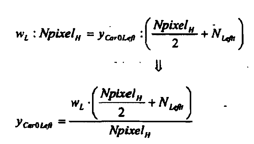
wenn das Fahrzeug nahe der linken Seite der Fahrbahn ist. - System nach Anspruch 8, bei dem die Steuermittel (U) eingerichtet sind, den Abstand zwischen dem Fahrzeug und den Begrenzungslinien (L) der virtuellen Fahrspur, zu der es gehört, nach den folgenden Beziehungen zu berechnen:


- System nach Anspruch 9, bei dem die Steuermittel (U) eingerichtet sind, die Zeit, die das Fahrzeug benötigen würde, um die virtuelle Begrenzungslinie (L), der es sich nähert, zu erreichen und zu kreuzen, d.h. die identifizierte virtuelle Fahrspur zu verlassen, als eine Funktion der Seitwärtsdriftgeschwindigkeit vy des Fahrzeugs und seiner Seitwärtsbeschleunigung ay nach folgenden Beziehungen zu berechen:


wobei d der Abstand zwischen dem Fahrzeug (V) und der Begrenzungslinie (L) der virtuellen Fahrspur auf der der Drift entsprechenden Seite ist. - System nach Anspruch 10, bei dem die Steuermittel (U) eingerichtet sind, als Funktion der Überschreitung der Schwelle des Mindestsicherheitsabstands von der Begrenzungslinie (L) der virtuellen Fahrspur, zu der das Fahrzeug gehört und/oder der Schwelle der minimalen Zeit bis zur Überquerung der Begrenzungslinie (L) der virtuellen Fahrspur, zu der das Fahrzeug (V) gehört, eine oder mehrere vorgegebene Strategien zum Zeichengeben an den Fahrer auszuführen.
- System nach einem der vorhergehenden Ansprüche, bei dem die Aufnahmemittel (C) eine einzige bei sichtbaren Wellenlängen arbeitende Aufnahmevorrichtung oder ein Paar von Aufnahmevorrichtungen verwendet, die eingerichtet sind, ein stereoskopisches Bild der Szene zu liefern.
- System nach Anspruch 12, bei dem die Aufnahmemittel (C) einen horizontalen Blickwinkel von im Wesentlichen gleich 40°, einen vertikalen Blickwinkel von im Wesentlichen gleich 30° und einen Orientierungswinkel in der Ebene in Bezug auf die Fahrtebene von im Wesentlichen zwischen 80° und 90° aufweisen.
- System nach Anspruch 13, bei dem die Aufnahmemittel (C) eingerichtet sind für eine automatische Steuerung des Ausschnitts des Blickfeldes (U).
- System nach Anspruch 13, bei dem die Aufnahmemittel (C) im Raum orientierbar sind, um ein Kurvenfahrmanöver des Fahrzeugs (V) zu verfolgen und so eine lokal gekrümmte Fahrbahn (R) aufzunehmen.
Priority Applications (3)
| Application Number | Priority Date | Filing Date | Title |
|---|---|---|---|
| DE602007012568T DE602007012568D1 (de) | 2007-12-28 | 2007-12-28 | Fahrassistenzsystem für ein Fahrzeug das auf einem Weg ohne Fahrspurabgrenzungslinien fährt |
| EP07425834A EP2075170B1 (de) | 2007-12-28 | 2007-12-28 | Fahrassistenzsystem für ein Fahrzeug das auf einem Weg ohne Fahrspurabgrenzungslinien fährt |
| BRPI0805756A BRPI0805756B1 (pt) | 2007-12-28 | 2008-12-17 | sistema de assistência ao guiar, para um veículo em viagem ao longo de uma rodovia com carência de linhas de demarcação de mão-de-direção |
Applications Claiming Priority (1)
| Application Number | Priority Date | Filing Date | Title |
|---|---|---|---|
| EP07425834A EP2075170B1 (de) | 2007-12-28 | 2007-12-28 | Fahrassistenzsystem für ein Fahrzeug das auf einem Weg ohne Fahrspurabgrenzungslinien fährt |
Publications (2)
| Publication Number | Publication Date |
|---|---|
| EP2075170A1 EP2075170A1 (de) | 2009-07-01 |
| EP2075170B1 true EP2075170B1 (de) | 2011-02-16 |
Family
ID=39494349
Family Applications (1)
| Application Number | Title | Priority Date | Filing Date |
|---|---|---|---|
| EP07425834A Active EP2075170B1 (de) | 2007-12-28 | 2007-12-28 | Fahrassistenzsystem für ein Fahrzeug das auf einem Weg ohne Fahrspurabgrenzungslinien fährt |
Country Status (3)
| Country | Link |
|---|---|
| EP (1) | EP2075170B1 (de) |
| BR (1) | BRPI0805756B1 (de) |
| DE (1) | DE602007012568D1 (de) |
Cited By (1)
| Publication number | Priority date | Publication date | Assignee | Title |
|---|---|---|---|---|
| EP3655298B1 (de) * | 2018-09-28 | 2023-04-26 | Baidu.com Times Technology (Beijing) Co., Ltd. | Tunnelbasiertes planungssystem für autonom fahrende fahrzeuge |
Families Citing this family (17)
| Publication number | Priority date | Publication date | Assignee | Title |
|---|---|---|---|---|
| KR101362324B1 (ko) * | 2012-06-05 | 2014-02-24 | 현대모비스 주식회사 | 차선 이탈 경보 시스템 및 방법 |
| US10176634B2 (en) * | 2015-10-16 | 2019-01-08 | Ford Global Technologies, Llc | Lane boundary detection data generation in virtual environment |
| US10121367B2 (en) * | 2016-04-29 | 2018-11-06 | Ford Global Technologies, Llc | Vehicle lane map estimation |
| US10048688B2 (en) | 2016-06-24 | 2018-08-14 | Qualcomm Incorporated | Dynamic lane definition |
| JP6686760B2 (ja) * | 2016-07-21 | 2020-04-22 | いすゞ自動車株式会社 | 画像処理装置及び画像処理方法 |
| CN106364403A (zh) * | 2016-10-14 | 2017-02-01 | 深圳市元征科技股份有限公司 | 一种车道识别方法及移动终端 |
| DE102017217091B4 (de) * | 2017-09-26 | 2022-11-24 | Ford Global Technologies, Llc | Verfahren zur Unterstützung eines Fahrers beim Halten der Fahrspur |
| CN108297866B (zh) * | 2018-01-03 | 2019-10-15 | 西安交通大学 | 一种车辆的车道保持控制方法 |
| CN110803161B (zh) * | 2018-08-02 | 2021-11-16 | 上海汽车集团股份有限公司 | 车道保持方法及车道保持辅助系统 |
| KR102622169B1 (ko) * | 2018-12-06 | 2024-01-08 | 팅크웨어(주) | 주행 영상을 이용하여 차간 거리를 측정하는 차간 거리 측정 방법, 차간 거리 측정 장치, 전자 기기, 컴퓨터 프로그램 및 컴퓨터 판독 가능한 기록 매체 |
| FR3094318B1 (fr) * | 2019-03-28 | 2021-02-26 | Renault Sas | Procédé de commande du positionnement d’un véhicule automobile sur une voie de circulation |
| CN113874268A (zh) * | 2019-05-22 | 2021-12-31 | 日立安斯泰莫株式会社 | 车辆控制装置 |
| CN111829549B (zh) * | 2020-07-30 | 2022-05-24 | 吉林大学 | 一种基于高精度地图的积雪路面虚拟车道线投影方法 |
| CN111931705B (zh) * | 2020-09-15 | 2024-12-31 | 徐工集团工程机械股份有限公司道路机械分公司 | 铰接式压路机全景环视系统及标定方法、铰接式压路机 |
| CN112519773B (zh) * | 2020-11-30 | 2022-08-05 | 南通路远科技信息有限公司 | 一种智能驾驶汽车的车道保持方法、装置及汽车 |
| CN113200052B (zh) * | 2021-05-06 | 2021-11-16 | 上海伯镭智能科技有限公司 | 一种用于无人驾驶的路况智能识别方法 |
| CN115468580B (zh) * | 2022-09-22 | 2024-12-13 | 星河智联汽车科技有限公司 | 一种车辆导航路线指示方法、装置及系统 |
Family Cites Families (5)
| Publication number | Priority date | Publication date | Assignee | Title |
|---|---|---|---|---|
| JP2887039B2 (ja) * | 1993-03-26 | 1999-04-26 | 三菱電機株式会社 | 車両周辺監視装置 |
| DE102004007072A1 (de) * | 2004-02-13 | 2005-09-08 | Audi Ag | Verfahren zum Betreiben eines Fahrerassistenzsystems und Fahrerassistenzsystem |
| JP3898709B2 (ja) * | 2004-05-19 | 2007-03-28 | 本田技研工業株式会社 | 車両用走行区分線認識装置 |
| JP4442402B2 (ja) * | 2004-11-26 | 2010-03-31 | 日産自動車株式会社 | 車両用運転操作補助装置および車両用運転操作補助装置を備えた車両 |
| JP4577013B2 (ja) * | 2004-12-28 | 2010-11-10 | 日産自動車株式会社 | 車線逸脱防止装置 |
-
2007
- 2007-12-28 EP EP07425834A patent/EP2075170B1/de active Active
- 2007-12-28 DE DE602007012568T patent/DE602007012568D1/de active Active
-
2008
- 2008-12-17 BR BRPI0805756A patent/BRPI0805756B1/pt active IP Right Grant
Cited By (1)
| Publication number | Priority date | Publication date | Assignee | Title |
|---|---|---|---|---|
| EP3655298B1 (de) * | 2018-09-28 | 2023-04-26 | Baidu.com Times Technology (Beijing) Co., Ltd. | Tunnelbasiertes planungssystem für autonom fahrende fahrzeuge |
Also Published As
| Publication number | Publication date |
|---|---|
| DE602007012568D1 (de) | 2011-03-31 |
| EP2075170A1 (de) | 2009-07-01 |
| BRPI0805756B1 (pt) | 2019-09-03 |
| BRPI0805756A2 (pt) | 2009-08-25 |
Similar Documents
| Publication | Publication Date | Title |
|---|---|---|
| EP2075170B1 (de) | Fahrassistenzsystem für ein Fahrzeug das auf einem Weg ohne Fahrspurabgrenzungslinien fährt | |
| US10269331B2 (en) | Display control device for vehicle | |
| US10564434B2 (en) | Display control device for vehicle | |
| US8354944B2 (en) | Night vision device | |
| CN107077792B (zh) | 行驶控制系统 | |
| EP3070928B1 (de) | Vorrichtung zur erkennung einer umgebung | |
| US9251715B2 (en) | Driver training system using heads-up display augmented reality graphics elements | |
| US7482909B2 (en) | Night vision device | |
| CN101998113B (zh) | 用于车辆的图像显示装置 | |
| US10395527B2 (en) | Method and control and detection device for a plausibility check of a wrong-way driving incident of a motor vehicle | |
| JP2021517675A5 (de) | ||
| JP2021517675A (ja) | 路面状態と天候に基づく環境影響を認識し評価するための方法及び装置 | |
| CN110865374A (zh) | 定位系统 | |
| DE102019202591A1 (de) | Verfahren zum Betreiben eines Fahrerinformationssystems in einem Ego-Fahrzeug und Fahrerinformationssystem | |
| US20130197804A1 (en) | Method for determining a virtual vehicle corridor | |
| US20220194425A1 (en) | Method for operating a vehicle configured for automated, in particular highly automated or autonomous driving | |
| EP1566060A1 (de) | Vorrichtung und verfahren zur verbesserung der sicht in einem kraftfahrzeug | |
| US20140152432A1 (en) | Method for Detecting a Traffic Lane by Means of a Camera | |
| US20240383479A1 (en) | Vehicular sensing system with lateral threat assessment | |
| DE102013224307A1 (de) | Verfahren und Anordnung zur Anzeige von Navigationsanweisungen | |
| CN116923094A (zh) | 增强现实平视显示器系统中的车道位置 | |
| CN115867475A (zh) | 用于车辆自动驾驶操作的方法和装置以及车辆 | |
| US20170248958A1 (en) | Adjacent lane verification for an automated vehicle | |
| EP1028387B1 (de) | Einrichtung zur Umfelderkennung, insbesondere zur Verkehrszeichenerkennung | |
| US11400861B2 (en) | Camera monitoring system |
Legal Events
| Date | Code | Title | Description |
|---|---|---|---|
| PUAI | Public reference made under article 153(3) epc to a published international application that has entered the european phase |
Free format text: ORIGINAL CODE: 0009012 |
|
| AK | Designated contracting states |
Kind code of ref document: A1 Designated state(s): AT BE BG CH CY CZ DE DK EE ES FI FR GB GR HU IE IS IT LI LT LU LV MC MT NL PL PT RO SE SI SK TR |
|
| AX | Request for extension of the european patent |
Extension state: AL BA HR MK RS |
|
| 17P | Request for examination filed |
Effective date: 20091229 |
|
| AKX | Designation fees paid |
Designated state(s): DE FR IT |
|
| GRAP | Despatch of communication of intention to grant a patent |
Free format text: ORIGINAL CODE: EPIDOSNIGR1 |
|
| RAP1 | Party data changed (applicant data changed or rights of an application transferred) |
Owner name: MAGNETI MARELLI S.P.A. |
|
| GRAS | Grant fee paid |
Free format text: ORIGINAL CODE: EPIDOSNIGR3 |
|
| GRAA | (expected) grant |
Free format text: ORIGINAL CODE: 0009210 |
|
| AK | Designated contracting states |
Kind code of ref document: B1 Designated state(s): DE FR IT |
|
| REF | Corresponds to: |
Ref document number: 602007012568 Country of ref document: DE Date of ref document: 20110331 Kind code of ref document: P |
|
| REG | Reference to a national code |
Ref country code: DE Ref legal event code: R096 Ref document number: 602007012568 Country of ref document: DE Effective date: 20110331 |
|
| PLBE | No opposition filed within time limit |
Free format text: ORIGINAL CODE: 0009261 |
|
| STAA | Information on the status of an ep patent application or granted ep patent |
Free format text: STATUS: NO OPPOSITION FILED WITHIN TIME LIMIT |
|
| 26N | No opposition filed |
Effective date: 20111117 |
|
| REG | Reference to a national code |
Ref country code: DE Ref legal event code: R097 Ref document number: 602007012568 Country of ref document: DE Effective date: 20111117 |
|
| REG | Reference to a national code |
Ref country code: FR Ref legal event code: PLFP Year of fee payment: 9 |
|
| REG | Reference to a national code |
Ref country code: FR Ref legal event code: PLFP Year of fee payment: 10 |
|
| REG | Reference to a national code |
Ref country code: FR Ref legal event code: PLFP Year of fee payment: 11 |
|
| PGFP | Annual fee paid to national office [announced via postgrant information from national office to epo] |
Ref country code: DE Payment date: 20251126 Year of fee payment: 19 |
|
| PGFP | Annual fee paid to national office [announced via postgrant information from national office to epo] |
Ref country code: IT Payment date: 20251119 Year of fee payment: 19 |
|
| PGFP | Annual fee paid to national office [announced via postgrant information from national office to epo] |
Ref country code: FR Payment date: 20251120 Year of fee payment: 19 |