EP2075217B1 - Industrielles Fahrzeug - Google Patents
Industrielles Fahrzeug Download PDFInfo
- Publication number
- EP2075217B1 EP2075217B1 EP08021365A EP08021365A EP2075217B1 EP 2075217 B1 EP2075217 B1 EP 2075217B1 EP 08021365 A EP08021365 A EP 08021365A EP 08021365 A EP08021365 A EP 08021365A EP 2075217 B1 EP2075217 B1 EP 2075217B1
- Authority
- EP
- European Patent Office
- Prior art keywords
- pump
- cargo
- handling
- driving
- clutch
- Prior art date
- Legal status (The legal status is an assumption and is not a legal conclusion. Google has not performed a legal analysis and makes no representation as to the accuracy of the status listed.)
- Not-in-force
Links
Images




Classifications
-
- B—PERFORMING OPERATIONS; TRANSPORTING
- B66—HOISTING; LIFTING; HAULING
- B66F—HOISTING, LIFTING, HAULING OR PUSHING, NOT OTHERWISE PROVIDED FOR, e.g. DEVICES WHICH APPLY A LIFTING OR PUSHING FORCE DIRECTLY TO THE SURFACE OF A LOAD
- B66F9/00—Devices for lifting or lowering bulky or heavy goods for loading or unloading purposes
- B66F9/06—Devices for lifting or lowering bulky or heavy goods for loading or unloading purposes movable, with their loads, on wheels or the like, e.g. fork-lift trucks
- B66F9/075—Constructional features or details
- B66F9/20—Means for actuating or controlling masts, platforms, or forks
- B66F9/22—Hydraulic devices or systems
-
- B—PERFORMING OPERATIONS; TRANSPORTING
- B60—VEHICLES IN GENERAL
- B60W—CONJOINT CONTROL OF VEHICLE SUB-UNITS OF DIFFERENT TYPE OR DIFFERENT FUNCTION; CONTROL SYSTEMS SPECIALLY ADAPTED FOR HYBRID VEHICLES; ROAD VEHICLE DRIVE CONTROL SYSTEMS FOR PURPOSES NOT RELATED TO THE CONTROL OF A PARTICULAR SUB-UNIT
- B60W10/00—Conjoint control of vehicle sub-units of different type or different function
- B60W10/04—Conjoint control of vehicle sub-units of different type or different function including control of propulsion units
- B60W10/06—Conjoint control of vehicle sub-units of different type or different function including control of propulsion units including control of combustion engines
-
- B—PERFORMING OPERATIONS; TRANSPORTING
- B60—VEHICLES IN GENERAL
- B60W—CONJOINT CONTROL OF VEHICLE SUB-UNITS OF DIFFERENT TYPE OR DIFFERENT FUNCTION; CONTROL SYSTEMS SPECIALLY ADAPTED FOR HYBRID VEHICLES; ROAD VEHICLE DRIVE CONTROL SYSTEMS FOR PURPOSES NOT RELATED TO THE CONTROL OF A PARTICULAR SUB-UNIT
- B60W10/00—Conjoint control of vehicle sub-units of different type or different function
- B60W10/10—Conjoint control of vehicle sub-units of different type or different function including control of change-speed gearings
- B60W10/101—Infinitely variable gearings
- B60W10/103—Infinitely variable gearings of fluid type
-
- B—PERFORMING OPERATIONS; TRANSPORTING
- B66—HOISTING; LIFTING; HAULING
- B66F—HOISTING, LIFTING, HAULING OR PUSHING, NOT OTHERWISE PROVIDED FOR, e.g. DEVICES WHICH APPLY A LIFTING OR PUSHING FORCE DIRECTLY TO THE SURFACE OF A LOAD
- B66F9/00—Devices for lifting or lowering bulky or heavy goods for loading or unloading purposes
- B66F9/06—Devices for lifting or lowering bulky or heavy goods for loading or unloading purposes movable, with their loads, on wheels or the like, e.g. fork-lift trucks
- B66F9/075—Constructional features or details
- B66F9/07572—Propulsion arrangements
Definitions
- This invention relates to driving of an equipment-driving pump in an industrial vehicle such as a forklift truck.
- An equipment-driving pump provided in an industrial vehicle such as a cargo-handling pump provided in a forklift truck is driven, for example, by an internal combustion engine that generates a motive force for running the industrial vehicle.
- the equipment-driving pump is maintained in an operative state as long as the internal combustion engine is operative.
- the cargo-handling pump that drives the forklift is connected, for example, to a pump impeller of a torque converter associated with an automatic transmission, via a reduction gear.
- a pump having a large discharge capacity is not preferable in terms of preventing the internal combustion engine from stalling.
- a cargo-handling pump having a large discharge capacity may cause the internal combustion engine to stall.
- the cargo-handling speed is limited by the pump discharge capacity and an output torque of the internal combustion engine.
- the pump discharge capacity is small, the operation speed of the forklift cannot be increased when required.
- JPHO1-136875 A published by the Japan Patent Office in 1989, proposes application of a variable capacity pump to an equipment-driving pump.
- JP2002-226198 A published by the Japan Patent Office in 2002
- JPH07-285787 A published by the Japan Patent Office in 1995
- JP 8-142704A discloses an industrial vehicle having the features of the preamble of claim 1.
- variable capacity pump When a variable capacity pump is used as a cargo-handling pump of a forklift truck, the relationship between an engine rotation speed and a pump discharge capacity can be controlled variably, and hence the aforesaid problem can be solved.
- a variable capacity pump has a complicated structure and is expensive compared with a fixed capacity pump. Further, a control device for controlling the discharge capacity of the pump is required. The implementation cost of the cargo-handling device associated with a variable capacity pump is therefore very expensive as a whole.
- the pump discharge capacity can be switched between two values and thus the aforesaid problem may be solved.
- the pump discharge capacity cannot be varied in a stepless fashion to an optimum value depending on engine operation conditions from a low load region to a high load region, or from an idle rotation speed region to a high rotation speed region.
- this invention provides an industrial vehicle comprising an internal combustion engine, a torque converter comprising a pump impeller connected to the internal combustion engine and a turbine runner, an automatic transmission connected to the turbine runner, a drive wheel connected to the automatic transmission, and an equipment-driving pump driven by a rotational torque of the turbine runner.
- FIG. 1 is a schematic diagram of a forklift-driving device provided in a forklift truck according to this invention.
- FIG. 2 is a control circuit diagram of various clutches with which the forklift truck is provided.
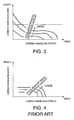
- FIG. 3 is a diagram showing a relationship between a cargo-handling load and a cargo-handling speed according to an accelerator opening realized by the forklift-driving device.
- FIG. 4 is a diagram showing a relationship between a cargo-handling load and a cargo-handling speed according to an accelerator opening realized by a forklift-driving device according to the prior art.
- FIG. 5 is a schematic diagram of a forklift-driving device provided in a forklift truck according to a second embodiment of this invention
- FIG. 6 is a schematic diagram of a forklift driving device, a hydraulic power steering device, and a hydraulic brake-boosting device provided in a forklift truck according to a third embodiment of this invention.
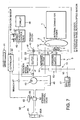
- FIG. 7 is a schematic diagram of a forklift driving device and a hydraulic power steering device provided in a forklift truck according to a fourth embodiment of this invention
- an internal combustion engine 1 which provides a motive force for running a forklift truck outputs rotational torque to drive wheels 17 of the forklift truck via a torque converter 2, an automatic transmission 3 provided with a forward/reverse change-over mechanism, and a fixed gear ratio reduction gear.
- the torque converter 2 has a known structure comprising a pump impeller 4 connected to a crankshaft of the internal combustion engine 1, a turbine runner 5 connected to an input shaft of the automatic transmission 3, a fixed hollow shaft fixed to a housing, and a stator supported by the fixed hollow shaft.
- a charge pump 7 is connected to the pump impeller 4 via a hollow shaft 6 that is supported to be free to rotate on the outer periphery of the fixed hollow shaft.
- the charge pump 7 operates synchronously with the internal combustion engine 1 to supply hydraulic pressure to electromagnetic proportional pressure control valves 21 and 22 shown in FIG. 2 , with which the automatic transmission 3 is provided, as well as to circulate working oil within the torque converter 2.
- the automatic transmission 3 comprises one forward gear 10 activated by a forward clutch 9 and one reverse gear 15 activated by a reverse clutch 14.
- the forward clutch 9 is engaged such that the automatic transmission 3 transmits a rotation of a turbine shaft 8 connected to the turbine runner 5 of the torque converter 2 to the forward gear 10a.
- the reverse clutch 14 is engaged, whereby the automatic transmission 3 transmits a rotation of the turbine shaft 8 to a reverse input shaft 13 via a drive gear 11 fixed to the turbine shaft 8 and a driven gear 12 meshed with the drive gear 11.
- the reverse clutch 14 By engaging the reverse clutch 14, the rotation of the reverse input shaft 13 is transmitted to the reverse gear 15 via the reverse clutch 14.
- the forward clutch 9 and the reverse clutch 14 are controlled such that only one of them can be engaged and an output torque of either the forward clutch 9 or the reverse clutch 14 under engagement is transmitted to an output shaft 16 of the automatic transmission 3 via the forward gear 10 or the reverse gear 15. The rotation of the output shaft 16 is then transmitted to the drive wheels 17 of the forklift truck.
- the gears of the automatic transmission 3 are not limited to those described above.
- the automatic transmission 3 may comprise, for example, two forward gears and one reverse gear, or two forward gears and two reverse gears.
- the structure of the automatic transmission 3 is also not limited to that described above.
- Oil pressurized by the charge pump 7 is supplied to the electromagnetic proportional pressure control valves 21 and 22 after being subjected to pressure regulation to a constant pressure in a pressure regulator 20.
- the electromagnetic proportional pressure control valve 21 controls a supplied pressure to a clutch engaging pressure corresponding to a command signal output from a controller 30 via a drive circuit 23 and supplies the clutch engaging pressure to the forward clutch 9.
- the electromagnetic proportional pressure control valve 22 controls a supplied pressure to a clutch engaging pressure corresponding to a command signal output from the controller 30 via a drive circuit 24 and supplies the clutch engaging pressure to the reverse clutch 14.
- Each of the forward clutch 9 and the reverse clutch 14 comprises a clutch cylinder which is activated according to a supplied hydraulic pressure, and a pair of multiple clutch discs at a drive side and a driven side which engage with each other according to activation of the clutch cylinder.
- the forward clutch 9 transmits a rotational torque to the output shaft 16 in a direction corresponding to forward driving of the forklift truck.
- the reverse clutch 14 transmits a rotational torque to the output shaft 16 in a direction corresponding to reverse driving of the forklift truck.
- the forward clutch 9 and the reverse clutch 14 vary a frictional torque transmission amount between the pair of multiple clutch discs according to a hydraulic pressure supplied from the electromagnetic proportional pressure control valves 21 and 22, respectively.
- a hydraulic pressure supplied from the electromagnetic proportional pressure control valves 21 and 22, respectively When the supplied hydraulic pressure is low, the frictional torque transmission amount between the pair of multiple clutch discs is small, but as the supplied hydraulic pressure increases, the frictional torque transmission amount between the pair of multiple clutch discs also increases.
- the electromagnetic proportional pressure control valve 21 is constituted by a solenoid valve and varies the hydraulic pressure supplied to the forward clutch 9 according to an exciting current supplied to a solenoid from the drive circuit 23 in response to a command signal output from the controller 30.
- the electromagnetic proportional pressure control valve 22 is constituted by a solenoid valve and varies the hydraulic pressure supplied to the reverse clutch 14 according to an exciting current supplied to a solenoid from the drive circuit 24 in response to a command signal output from the controller 30.
- the electromagnetic proportional pressure control valves 21 and 22 may be constituted by valves which operate in response to the exciting current of the solenoid, or pulse width modulation (PWM) valves which operate in response to a pulse width or a duty ratio of the exciting current of the solenoid.
- PWM pulse width modulation
- the frictional torque transmission amount of the forward clutch 9 and that of the reverse clutch 14 are zero when they are not provided with hydraulic pressure.
- Braking of the drive wheels 17 of the forklift truck is activated by a braking pressure generated by a master cylinder 26 which operates in response to depression of a brake pedal 25 by an operator of the forklift truck.
- Detection data are input into the controller 30 via signal circuits from an accelerator pedal depression sensor 27 which detects a depression amount of an accelerator pedal with which the forklift truck is provided, an inhibitor switch 28 which detects a current position of a selector lever which switches between forward driving and reverse driving of the forklift truck and outputs a signal corresponding to any of Forward (F), Reverse (R), and Neutral (N), an inching pedal depression sensor 29 which detects a depression amount of an inching pedal with which the forklift truck is provided, and a pressure sensor 32 which detects a braking pressure generated by the master cylinder 26 in accordance with depression of the brake pedal 25.
- a brake pedal depression sensor which detects a depression amount of the brake pedal 25.
- the inching pedal when depressed, reduces the engaging pressure of the forward clutch 9 or the reverse clutch 14 under engagement, and when depressed further, depresses the brake pedal 25 together therewith.
- the inching pedal When the inching pedal is depressed deeply, therefore, the brake pressure rises as the clutch pressure lowers.
- Further detection data are input into the controller 30 via signal circuits from a position sensor 49 which detects if a cargo-handling control lever 47 that is operated by the operator is in a cargo-handling position, a rotation speed sensor 31 which detects a rotation speed of the turbine shaft 8, and a rotation speed sensor 33 which detects a rotation speed of the output shaft 16.
- the controller 30 outputs command signals corresponding to the engaging pressures of the forward clutch 9 and the reverse clutch 14 to drive the circuits 23 and 24, respectively.
- the controller 30 supplies an exciting current to the electromagnetic proportional pressure control valve 21 via the drive circuit 23, thereby supplying the forward clutch 9 with hydraulic pressure such that the forward clutch 9 engages.
- the controller 30 supplies an exciting current to the electromagnetic proportional pressure control valve 22 via the drive circuit 24, thereby supplying the reverse clutch 14 with hydraulic pressure such that the reverse clutch 14 engages.
- the controller 30 is constituted by a microcomputer comprising a central processing unit (CPU), a read-only memory (ROM), a random access memory (RAM), and an input/output interface (I/O interface).
- the controller 30 may be constituted by a plurality of microcomputers.
- the forklift truck comprises a cargo-handling pump 40 as an equipment-driving pump to drive a forklift 48 using hydraulic pressure.
- a forklift-driving device drives the cargo-handling pump 40 using a rotational torque of the turbine shaft 8 connected to the turbine runner 5 of the torque converter 2.
- a pump-driving gear 41 meshed with the driven gear 12 of the automatic transmission 3 is provided to drive the cargo-handling pump 40.
- the cargo-handling pump 40 is therefore not directly driven by the internal combustion engine 1 but by the turbine runner 5 of the torque converter 2.
- the cargo-handling pump 40 suctions working oil from a working oil tank 45 and supplies the cargo-handling control valve 46 with pressurized working oil.
- the cargo-handling control valve 46 supplies the pressurized working oil to the forklift 48 in response to an operation of the cargo-handling control lever 47 by the operator and causes the forklift 48 to perform cargo-handling.
- the cargo-handling control lever 47 When the cargo-handling control lever 47 is not operated, the cargo-handling control valve 46 recirculates the pressurized working oil discharged by the cargo-handling pump 40 to the working oil tank 45.
- the pump-driving gear 41 and the cargo-handling pump 40 are connected via a one-way clutch 42.
- the one-way clutch 42 transmits rotational torque of the pump-driving gear 41 in a specified direction from the pump-driving gear 41 to the cargo-handling pump 40 while preventing rotational torque from being transmitted in the opposite direction from the pump-driving gear 41 to the cargo-handling pump 40.
- the turbine runner 5 normally rotates in the same direction as the pump impeller 4. In this case, the pump-driving gear 41 rotates in the specified direction.
- the turbine runner 5 When rotational torque is input into the turbine runner 5 in the opposite direction from the drive wheels 17, the turbine runner 5 may rotate in the opposite direction with respect to the rotation of the pump impeller 4.
- the pump-driving gear 41 rotates in the opposite direction to the specified direction.
- the one-way clutch 42 is preferably disposed between the pump-driving gear 41 and a pump-driving shaft 39 which supports the pump-driving gear 41.
- the forklift-driving device further comprises a liquid crystal display 44A which indicates a cargo-handling speed on a bar graph.
- the cargo-handling speed is a rotation speed of the cargo-handling pump 40, which is obtained by converting the rotation speed of the turbine shaft 8 detected by the rotation speed sensor 31 using a gear ratio of the pump-driving gear 41 with respect to the drive gear 11. Since the cargo-handling speed does not necessarily correspond to the rotation speed of the internal combustion engine 1 in this forklift driving device, the rotation speed of the cargo-handling pump 40, which represents the cargo-handling speed, is indicated on the liquid crystal display 44A such that the operator of the forklift truck can recognize the cargo-handling speed directly.
- a rotation speed sensor 43 as shown in FIG. 2 may be provided to detect the rotation speed of the cargo-handling pump 40 directly.
- the rotation speed of the pump-driving gear 41 may be detected by a rotation speed sensor 43A as a value equivalent to the rotation speed of the cargo-handling pump 40.
- the liquid crystal display 44A may be replaced by an analog meter 44B shown by a broken line in the figure.
- An analog-style display is preferable in terms of intuitive recognition of the cargo-handling speed.
- the driving load of the cargo-handling pump 40 increases. Accordingly, the rotation speed and the pump discharge flow rate of the cargo-handling pump 40 decreases. As a result, a slip rate between the pump impeller 4 and the turbine runner 5 of the torque converter 2 increases. The stall torque which increases together with the slip rate promotes an increase in the driving torque of the cargo-handling pump 40 so as to raise the discharge pressure of the cargo-handling pump 40. As a result, the pump discharge flow rate varies depending on the cargo-handling load.
- the cargo-handling load corresponds to the pump discharge pressure
- the pump discharge flow rate corresponds to the pump rotation speed and the cargo-handling speed.
- the cargo-handling pump In a prior art forklift-driving device in which the cargo-handling pump is connected to the pump impeller of the torque converter, the cargo-handling pump is rotated at a fixed ratio relative to the engine rotation speed.
- the discharge flow rate or the pump rotation speed of the cargo-handling pump varies in a fixed relation to the rotation speed of the internal combustion engine while its maximum pump discharge pressure depends on a maximum output torque of the internal combustion engine 1 which drives the cargo-handling pump.
- the maximum output torque of the internal combustion engine 1 is smallest when the internal combustion engine is running idle, increases as the rotation speed of the engine increases, reaches a maximum at a predetermined rotation speed, and thereafter decreases as the rotation speed increases further.
- an input torque into the cargo-handling pump 40 varies in response to the rotation speed of the internal combustion engine.
- the rotation speed of the internal combustion engine decreases and stalling may occur in the internal combustion engine.
- the operator must depress the accelerator pedal so as to increase the output torque of the internal combustion engine because the rotation speed of the internal combustion engine must be increased to increase the output torque thereof.
- a reduction gear is provided between the internal combustion engine and the cargo-handling pump.
- the cargo-handling pump When the accelerator pedal is depressed to a predetermined extent, the cargo-handling pump generates a pump discharge pressure which meets the cargo-handling operation load.
- the cargo-handling speed of the cargo-handling device is limited by a cargo-handling control valve which limits the flow rate of working oil supplied from the cargo-handling pump to the forklift.
- the lifting force or in other words the cargo-handling load increases as the depression amount of the accelerator pedal increases while on the other hand the cargo-handling speed is limited by the cargo-handling control valve.
- the cargo-handling control valve in the prior art forklift driving device recirculates a surplus amount of the working oil discharged by the cargo-handling pump at a greater flow rate than a fixed flow rate to the working oil tank.
- energy efficiency of this forklift-driving device is low and the temperature of the working oil rises to a high degree.
- the working oil tank is required therefore to have a large capacity to promote heat radiation of recirculated working oil. Even when the recirculated working oil is cooled in a working oil cooler, a working oil cooler of large capacity is required.
- the pump discharge flow rate varies according to the cargo-handling load.
- the cargo-handling load and the pump discharge flow rate are inversely proportional irrespective of the accelerator pedal depression amount. That is to say, the cargo-handling speed is relatively low in a heavy load and increases as the load decreases.
- the cargo-handling load can be adjusted in accordance with depression amount of the accelerator pedal. This is an ideal characteristic for a cargo-handling device.
- the size of a hydraulic cylinder used for driving the forklift 48 can be decreased with respect to an identical load.
- the forklift 48 can handle a heavier cargo using a hydraulic cylinder of an identical size to that used in the prior art forklift-driving device.
- the temperature rise in the working oil is small and the capacity of the working oil tank 45 can be reduced.
- a working oil cooler is therefore not necessary. Even when provided, a working oil cooler of a small size can cool the working oil sufficiently.
- a cargo-handling operation of a forklift truck is generally performed in an inching state where the inching pedal is depressed, or in a stationary state where the automatic transmission 3 is in the Neutral position and a parking brake is activated.
- the cargo-handling pump 40 since the cargo-handling pump 40 is connected to the turbine runner 5, the cargo-handling pump 40 is not operated when the above operation is performed, and hence the operator realizes the operation mistake easily.
- the forklift truck switches between the forward gear and the reverse gear frequently to perform a cargo-handling operation. If a switch from the forward gear to the reverse gear is performed to change the direction of travel without adequately decreasing the forward running speed of the forklift truck, the forward/reverse change-over mechanism changes over from forward running to reverse running while the forklift truck is still traveling forward. As a result, the turbine runner 5 of the torque converter 2 is forced to rotate in an opposite direction to the rotation direction of the pump impeller 4.
- the pump-driving gear 41 and the cargo-handling pump 40 are connected via the one-way clutch 42. Accordingly, even when the turbine runner 5 rotates in the opposite direction to the rotation direction of the pump impeller 4, the cargo-handling pump 40 does not rotate in a direction other than the normal direction. The cargo-handling pump 40 therefore does not suffer a negative pressure due to rotation of the cargo-handling pump 40 in a reverse direction, and the forklift 48 is protected from the adverse effects of the negative pressure in the cargo-handling pump 40.
- a simple engaging/ disengaging clutch may be provided between the pump-driving gear 41 and the cargo-handling pump 40 as well as a sensor which detects a rotation direction of the turbine runner 5.
- the controller 30 keeps the clutch in the engaged state as long as the turbine runner 5 is rotating in the normal direction, and disengages the clutch when the turbine runner 5 starts to rotate in the reverse direction.
- Using the one-way clutch 42 is however more economical and installation thereof is also easy in comparison with the engaging/ disengaging clutch.
- the charge pump 7 which generates a hydraulic pressure required for the operation of the automatic transmission 3 is connected to the pump impeller 4.
- the charge pump 7 therefore rotates in a fixed relation with the internal combustion engine 1.
- This is a general structure of a charge pump for an automatic transmission. This invention is therefore implemented without affecting the driving mechanism of the charge pump.
- the pump-driving gear 41 meshes with the driven gear 12 of the automatic transmission 3 to drive the cargo-handling pump 40 using the turbine runner 5.
- An idler gear is generally required to extract rotation from a part between the torque converter 2 and the automatic transmission 3, but by using the pump-driving gear 41 meshed with the driven gear 12, the cargo-handling pump 40 can be driven under a simple construction without an idler gear.
- the cargo-handling speed does not directly correspond to the rotation speed of the internal combustion engine 1.
- the rotation speed of the cargo-handling pump 40 is indicated on the bar graph of the liquid crystal display 44A or on the analog meter 44B mounted on this forklift truck, and the operator can thereby grasp the cargo-handling speed directly.
- the rotation speed of the cargo-handling pump 40 indicated on the liquid crystal display 44A or the analog meter 44B does not show an increase. The operator thereby recognizes the operation mistake easily.
- a clutch 50 is provided between the pump-driving shaft 39 and the cargo-handling pump 40.
- the pump-driving shaft 39 is connected to the pump-driving gear 41 via the one-way clutch 42 as in the case of the first embodiment.
- the controller 30 is programmed to determine the position of the cargo-handling control lever 47 on the basis of the position signal input from the position sensor 49, and when the cargo-handling control lever 47 is in the cargo-handling position, to engage the clutch 50 such that the cargo-handling pump 40 is driven by the pump-driving gear 41 to supply the forklift 48 with pressurized working oil.
- the controller 30 releases the clutch 50 to stop the operation of the cargo-handling pump 40 and stop the supply of pressurized working oil to the forklift 48.
- the clutch 50 is controlled via a drive circuit 51 which generates an electric control current in accordance with a command signal output from the controller 30 and an electromagnetic proportional pressure control valve 52 which controls an engaging pressure of the clutch 50 in response to the electric control current output from the drive circuit 51.
- the forklift driving device further comprises a booster pump 53 attached to the cargo-handling pump 40 to supply the hydraulic brake-boosting device 55 or the like with hydraulic pressure, and a brake pedal switch 54 which detects depression of the brake pedal 25 and inputs a braking signal into the controller 30 via a signal circuit.
- the time period during which the forklift 48 is driven corresponds to a part of a time period during which the forklift truck is operative.
- the cargo-handling pump 40 always discharges pressurized working oil as long as the turbine runner 5 is rotating.
- the controller 30 releases the clutch 50 so as to stop the operation of the cargo-handling pump 40 when the cargo-handling control lever 47 is not in the cargo-handling position.
- the controller 30, having determined that the brake pedal 25 is depressed on the basis of the braking signal input from the brake pedal switch 54, engages the clutch 50 to activate torque transmission to the cargo-handling pump 40 and the booster pump 53 such that the booster pump 53 supplies the hydraulic brake-boosting device 55 with pressurized working oil required for braking.
- a time period during which braking is applied is also limited to a part of a time period during which the forklift truck is operative.
- the other components of the forklift-driving device are identical to those of the first embodiment.
- the cargo-handling pump 40 and the booster pump 53 are operated only when either of them are required to be operative, the energy consumption of the pumps 40 and 53 can be suppressed and temperature increases in the pressurized working oil discharged from the pumps 40 and 53 are further prevented.
- a forklift truck comprises a forklift driving device and a hydraulic power steering device 60 which is independent of the forklift-driving device.
- the forklift-driving device corresponds to the forklift-driving device according to the second embodiment from which the hydraulic brake-boosting device 55 and the booster pump 53 are removed.
- the hydraulic power steering device 60 is a full hydraulic power steering device comprising a hydraulic pump 61 directly driven by the internal combustion engine 1, and a double-rod type steering cylinder 65 which operates using pressurized working oil discharged from the hydraulic pump 61.
- the pressurized working oil discharged from the hydraulic pump 61 is also used for driving the hydraulic brake-boosting device 55.
- the pressurized working oil discharged from the hydraulic pump 61 is supplied to the steering cylinder 65 via a steering control valve 64.
- the steering control valve 64 comprises a metering device known as an orbit pump which rotates in response to an operation of a steering wheel 63 by the operator, and a change-over valve which selectively supplies either of the two oil chambers in the steering cylinder 65 with the pressurized working oil discharged from the hydraulic pump 61 in accordance with a steering direction of the steering wheel 63.
- the orbit pump regulates a flow rate of the pressurized working oil supplied to the steering cylinder 65 from the hydraulic pump 61 to a flow rate corresponding to the steering speed of the steering wheel 63.
- the steering cylinder 65 drives a piston rod 65A in an axial direction depending on the working oil supply direction so as to steer the steered wheels of the forklift truck to the right or left via a knuckle arm.
- a hydraulic brake-boosting device 55 is connected to a hydraulic pressure supply passage which supplies the pressurized working oil discharged from the hydraulic pump 61 to the steering control valve 64.
- the hydraulic power steering device 60 and the hydraulic brake-boosting device 55 are driven together by the oil discharged from the hydraulic pump 61.
- a flow control valve 62 is installed in the hydraulic pressure supply passage between the hydraulic pump 61 and the hydraulic brake-boosting device 55.
- the flow control valve 62 has a function to maintain the flow rate of the pressurized working oil supplied to the hydraulic power steering device 60 and the hydraulic brake-boosting device 55 from the hydraulic pump 61 at a constant level, irrespective of the rotation speed of the internal combustion engine 1.
- the hydraulic power steering device 60 should not be limited to the above constitution.
- a hydraulic power steering device provided with a feedback control system can also be applied.
- this feedback control system a steered amount of the steered wheels is detected, and the oil discharged from the hydraulic pump 61 is supplied to either of the two oil chambers in the steering cylinder 65 depending on the result of a comparison between the steered amount of the steered wheels and the steering amount of the steering wheel 63.
- the cargo-handling pump 40 and the hydraulic pump 61 for the hydraulic power steering device 60 are separated as described above.
- the operation frequency of the forklift 48 is relatively low.
- the output torque of the internal combustion engine 1 is used to supply a motive force for running the forklift truck via the forward clutch 9 or the reverse clutch 14 and a driving force of the hydraulic pump 61 for operating the hydraulic power steering device 60.
- the operation frequency of the forklift 48 is relatively high. In this state, the forklift truck functions as follows.
- the controller 30 releases the clutch 50 so as to stop the operation of the cargo-handling pump 40 and suppress energy consumption by the internal combustion engine 1.
- the controller 30 engages the clutch 50 to drive the cargo-handling pump 40 such that the output torque of the internal combustion engine 1 is used exclusively for the cargo-handling operation.
- the forklift truck drives the cargo-handling pump 40 only when it is required to be operative, the energy consumption of the cargo-handling pump 40 can be suppressed and temperature increases in the pressurized working oil discharged from the cargo-handling pump 40 are further prevented.
- the capacity of each pump is set to an optimum value for achieving the object.
- a large capacity pump is required to be operated normally.
- a forklift truck uses the cargo-handling pump 40 as a hydraulic pump for the hydraulic power steering device 60.
- the forklift-driving device is identical to that of the third embodiment.
- the hydraulic power steering device 60 comprises a steering wheel 63, a steering control valve 64, and a steering cylinder 65 as in the case of the third embodiment.
- a steering wheel rotation speed sensor 68 is further attached to the steering wheel 63.
- the steering wheel rotation speed sensor 68 detects a rotation speed of the steering wheel 63 and inputs it into the controller 30 via a signal circuit.
- the oil discharged from the cargo-handling pump 40 bifurcates to the cargo-handling control valve 46 and the hydraulic power steering device 60 via a branch 67.
- the controller 30 engages the clutch 50 to supply the pressurized working oil discharged from the cargo-handling pump 40 to the hydraulic power steering device 60 when the steering wheel rotation speed is equal to or higher than a predetermined speed.
- the controller 30 also engages the clutch 50 to supply the pressurized oil discharged from the cargo-handling pump 40 to both the hydraulic power steering device 60 and the cargo-handling control valve 46 when the cargo-handling control lever 47 is in the cargo-handling position corresponding to the signal input from the position sensor 49 and the steering wheel rotation speed is equal to or higher than a predetermined speed.
- the controller 30 reduces the engaging pressure of the forward clutch 9 or the reverse clutch 14 under engagement from a predetermined engaging pressure.
- the cargo-handling pump 40 also serves as a hydraulic pump for driving the hydraulic power steering device 60.
- the cargo-handling pump 40 may not provide sufficient working oil for a steering action. The operator may then feel that the steering operation is heavy.
- the controller 30 reduces the engaging pressure of the forward clutch 9 or the reverse clutch 14 under engagement to increase the rotation speed of the turbine shaft 8. Reducing the engaging pressure of the forward clutch 9 or the reverse clutch 14 under engagement in this speed region is also preferable in terms of decreasing the fuel consumption and engine load, and cooling the working oil.
- the engaging pressure of the forward clutch 9 and the reverse clutch 14 is electronically controlled via the electromagnetic proportional pressure control valves 21 and 22, respectively, and the controller 30 can easily reduce the engaging pressure by outputting a corresponding command signal to the drive circuit 23 or 24.
- the forklift truck drives the cargo-handling pump 40 only when it is required to be operative, the energy consumption of the cargo-handling pump 40 can be suppressed and temperature increases in the pressurized working oil discharged from the cargo-handling pump 40 are further prevented.
- the cargo-handling pump 40 also serves as a hydraulic pump for driving the hydraulic power steering device 60, whereby the constitution of hydraulic equipment of the forklift truck is simplified. Further, a minimum discharge amount of the cargo-handling pump 40 is ensured at an extremely low speed running.
Landscapes
- Engineering & Computer Science (AREA)
- Chemical & Material Sciences (AREA)
- Combustion & Propulsion (AREA)
- Transportation (AREA)
- Mechanical Engineering (AREA)
- Structural Engineering (AREA)
- Civil Engineering (AREA)
- Life Sciences & Earth Sciences (AREA)
- Geology (AREA)
- Forklifts And Lifting Vehicles (AREA)
- Auxiliary Drives, Propulsion Controls, And Safety Devices (AREA)
- Arrangement Of Transmissions (AREA)
Claims (9)
- Industriefahrzeug, umfassend:einen Verbrennungsmotor (1);einen Drehmomentwandler (2) mit einem Pumpenflügelrad (4), das mit dem Verbrennungsmotor (1) und einem Turbinenlaufrad (5) verbunden ist;ein Automatikgetriebe (3), das mit dem Turbinenlaufrad (5) verbunden ist;ein Antriebsrad (17), das mit dem Automatikgetriebe (3) verbunden ist; undeine Geräteantriebspumpe (40), die durch ein Drehmoment des Turbinenlaufrads (5) angetrieben wird;gekennzeichnet durcheine Einwegkupplung (42), die das Drehmoment des Turbinenlaufrads (5) zur Geräteantriebspumpe (40) überträgt, wenn das Turbinenlaufrad (5) in einer gleichen Richtung wie das Pumpenflügelrad (4) dreht, während sie verhindert, dass das Drehmoment des Turbinenlaufrads (5) zur Geräteantriebspumpe (40) übertragen wird, wenn das Turbinenlaufrad (5) in einer entgegengesetzten Richtung zum Pumpenflügelrad (4) dreht.
- Industriefahrzeug nach Anspruch 1, wobei das Automatikgetriebe (3) umfasst:ein Antriebszahnrad (11), das mit dem Turbinenlaufrad (5) verbunden ist,eine Vorwärtskupplung (9), die das Antriebszahnrad (11) und das Antriebsrad (17) verbindet, wenn sie eingerückt ist, während sie das Antriebszahnrad (11) und das Antriebsrad (17) trennt, wenn sie ausgerückt ist,ein angetriebenes Zahnrad (12), das mit dem Antriebszahnrad (11) in Eingriff kommt, undeine Rückwärtskupplung (14), die das angetriebene Zahnrad (12) und das Antriebsrad (17) verbindet, wenn sie eingerückt ist, während sie das angetriebene Zahnrad (12) und das Antriebsrad (17) trennt, wenn sie ausgerückt ist,und das Industriefahrzeug ferner ein Pumpenantriebszahnrad (41) umfasst, das mit dem angetriebenen Zahnrad (12) in Eingriff kommt, um die Geräteantriebspumpe (40) anzutreiben.
- Industriefahrzeug nach Anspruch 2, ferner umfassend eine Kupplung (50), die das Pumpenantriebszahnrad (41) und die Geräteantriebspumpe (40) verbindet, wenn sie eingerückt ist, während sie das Pumpenantriebszahnrad (41) und die Geräteantriebspumpe (40) trennt, wenn sie ausgerückt ist.
- lndustriefahrzeug nach Anspruch 2 oder Anspruch 3, ferner umfassend eine hydraulische Servolenkvorrichtung (60), die mittels Verwendung von Öl, das von der Geräteantriebspumpe (40) ausgegeben wird, funktioniert, und eine Steuervorrichtung, die einen Eingriffsdruck der Vorwärtskupplung (9) oder der Rückwärtskupplung (14) im Eingriff verringert, wenn eine Drehzahl des Turbinenlaufrads (5) gleich oder geringer als eine vorbestimmte Drehzahl ist.
- Industriefahrzeug nach einem der Anspräche 2 bis 4, ferner umfassend eine Ladepumpe (7), die mit dem Pumpenflügelrad (4) verbunden ist, um einen Hydraulikdruck für einen Eingriff zur Vorwärtskupplung (9) und zur Rückwärtskupplung (14) zuzuführen.
- Industriefahrzeug nach einem der Ansprüche 1 bis 5, ferner umfassend eine Frachtgut-Handhabungsvorrichtung (48), die mittels Verwendung des Öls, das von der Geräteantriebspumpe (40) ausgegeben wird, funktioniert.
- Industriefahrzeug nach einem der Ansprüche 1 bis 6, ferner umfassend eine Anzeigevorrichtung (44A, 44B), die Informationen in Bezug auf eine Drehzahl der Geräteantriebspumpe (40) anzeigt.
- Industriefahrzeug nach einem der Ansprüche 1 bis 7, ferner umfassend eine Drucksteigerungspumpe (53), die mit der Geräteantriebspumpe (40) zusammenarbeitet, und eine hydraulische Bremsverstärkungsvorrichtung (55), die mittels Verwendung von Öl, das von der Drucksteigerungspumpe (53) ausgegeben wird, das Bremsen des Fahrzeugs unterstützt.
- Industriefahrzeug nach einem der Ansprüche 1 bis 7, ferner umfassend eine Hydraulikpumpe (61), die direkt vom Verbrennungsmotor (1) angetrieben wird, und eine hydraulische Bremsverstärkungsvorrichtung (55) und eine hydraulische Servolenkvorrichtung (60), die beide mittels Öl, das von der Hydraulikpumpe (61) ausgegeben wird, funktionieren.
Applications Claiming Priority (1)
| Application Number | Priority Date | Filing Date | Title |
|---|---|---|---|
| JP2007332167A JP4670865B2 (ja) | 2007-12-25 | 2007-12-25 | 産業車両における作業機用ポンプの駆動装置 |
Publications (3)
| Publication Number | Publication Date |
|---|---|
| EP2075217A2 EP2075217A2 (de) | 2009-07-01 |
| EP2075217A3 EP2075217A3 (de) | 2010-04-14 |
| EP2075217B1 true EP2075217B1 (de) | 2011-10-26 |
Family
ID=40532224
Family Applications (1)
| Application Number | Title | Priority Date | Filing Date |
|---|---|---|---|
| EP08021365A Not-in-force EP2075217B1 (de) | 2007-12-25 | 2008-12-09 | Industrielles Fahrzeug |
Country Status (4)
| Country | Link |
|---|---|
| US (1) | US20090159358A1 (de) |
| EP (1) | EP2075217B1 (de) |
| JP (1) | JP4670865B2 (de) |
| ES (1) | ES2374753T3 (de) |
Families Citing this family (7)
| Publication number | Priority date | Publication date | Assignee | Title |
|---|---|---|---|---|
| JP4941545B2 (ja) * | 2009-12-03 | 2012-05-30 | 株式会社豊田自動織機 | ハイブリッド型産業車両 |
| JP5854265B2 (ja) * | 2011-11-08 | 2016-02-09 | 株式会社ジェイテクト | 操舵機構の制御装置 |
| JP6007858B2 (ja) * | 2013-05-13 | 2016-10-12 | 株式会社豊田自動織機 | 産業車両 |
| CN103318254B (zh) * | 2013-07-05 | 2015-09-16 | 徐州重型机械有限公司 | 一种起重机后桥转向自锁控制系统 |
| DE202014009101U1 (de) * | 2013-11-19 | 2015-02-09 | Nacco Materials Handling Group, Inc. | Rückwärts-Steuergriff für einen Stapler |
| KR101963837B1 (ko) * | 2017-12-19 | 2019-07-31 | 금아파워텍주식회사 | 트랜스미션내 유압모터와 토크컨버터가 구비된 유압하이브리드 변속기 |
| KR101963834B1 (ko) * | 2017-12-19 | 2019-07-31 | 금아파워텍주식회사 | 유압모터의 단속기능을 구비한 유압하이브리드 변속기 |
Family Cites Families (25)
| Publication number | Priority date | Publication date | Assignee | Title |
|---|---|---|---|---|
| US3006199A (en) * | 1956-03-14 | 1961-10-31 | Gen Motors Corp | Torque transmitting mechanism |
| US3583243A (en) * | 1969-05-05 | 1971-06-08 | Harry R Wilson | Method and apparatus for controlling vehicle drive and power takeoff |
| US3887049A (en) * | 1970-09-24 | 1975-06-03 | Toyota Motor Co Ltd | Hydraulic controls for transmission and brake systems with pressure booster |
| JPS5633399A (en) * | 1979-08-20 | 1981-04-03 | Komatsu Forklift | Cargo work car |
| US4705450A (en) * | 1985-12-11 | 1987-11-10 | The Gradall Company | Single engine excavator with remote control |
| JP2518320B2 (ja) | 1987-11-20 | 1996-07-24 | 株式会社豊田自動織機製作所 | パワ―ステアリング装置の油圧ポンプ制御装置 |
| JPH02197424A (ja) * | 1989-01-24 | 1990-08-06 | Nikken:Kk | 車両用動力取出装置 |
| JPH05106243A (ja) * | 1991-10-15 | 1993-04-27 | Hitachi Constr Mach Co Ltd | 自走式作業機の制御装置 |
| JP3532595B2 (ja) * | 1993-08-23 | 2004-05-31 | ジヤトコ株式会社 | 動力取出装置付自動変速機搭載車両のロックアップ制御方法およびその装置 |
| IT1269440B (it) * | 1994-01-19 | 1997-04-01 | Fita Om Carrelli Elevatori S P | Carrello elevatore a motorizzazione elettrica |
| JP2798355B2 (ja) | 1994-04-20 | 1998-09-17 | 古河機械金属株式会社 | クレーンの過負荷防止装置 |
| JPH08142704A (ja) * | 1994-11-28 | 1996-06-04 | Mitsubishi Motors Corp | トルクコンバータ式オートマチックトランスミッション付作業車両 |
| US5720358A (en) * | 1995-12-06 | 1998-02-24 | Caterpillar Inc. | Apparatus for controlling the torque on a power train and method of operating the same |
| JP2000177410A (ja) * | 1998-12-11 | 2000-06-27 | Fuji Heavy Ind Ltd | 作業用車両 |
| JP2000211397A (ja) * | 1999-01-20 | 2000-08-02 | Niigata Converter Co Ltd | ディ―ゼル車両の動力伝達装置 |
| JP2000262106A (ja) * | 1999-03-19 | 2000-09-26 | Yanmar Agricult Equip Co Ltd | 管理作業車 |
| AU2001281851A1 (en) * | 2000-07-17 | 2002-01-30 | Abm Greiffenberger Antriebstechnik Gmbh | Method for sensorless drive control of an electric vehicle and drive control operating according to said method |
| JP2002174332A (ja) * | 2000-09-18 | 2002-06-21 | Fuji Heavy Ind Ltd | 作業用車両 |
| JP2002226198A (ja) | 2001-02-01 | 2002-08-14 | Komatsu Forklift Co Ltd | フォークリフトトラックにおける油圧回路装置 |
| US6615443B2 (en) * | 2001-04-04 | 2003-09-09 | Mohawk Milling & Sweeping Corp. | Stall converter for single engine sweeper |
| DE10316532B4 (de) * | 2002-04-12 | 2008-11-27 | Mitsubishi Fuso Truck And Bus Corp. | Hydraulisches Verstärkersystem für Bremsanlage |
| JP4484467B2 (ja) * | 2003-08-01 | 2010-06-16 | 日立建機株式会社 | 走行式油圧作業機 |
| JP2007022379A (ja) * | 2005-07-19 | 2007-02-01 | Kanzaki Kokyukoki Mfg Co Ltd | 作業運搬車 |
| JP2007332167A (ja) | 2006-05-17 | 2007-12-27 | Mitsubishi Rayon Co Ltd | ポリエステル樹脂組成物、その製造方法、およびポリエステル成形体 |
| US7765884B2 (en) * | 2007-09-27 | 2010-08-03 | Ford Global Technologies, Llc | Vehicle powertrain having live power take-off |
-
2007
- 2007-12-25 JP JP2007332167A patent/JP4670865B2/ja not_active Expired - Fee Related
-
2008
- 2008-12-09 ES ES08021365T patent/ES2374753T3/es active Active
- 2008-12-09 EP EP08021365A patent/EP2075217B1/de not_active Not-in-force
- 2008-12-18 US US12/338,676 patent/US20090159358A1/en not_active Abandoned
Also Published As
| Publication number | Publication date |
|---|---|
| US20090159358A1 (en) | 2009-06-25 |
| JP4670865B2 (ja) | 2011-04-13 |
| EP2075217A3 (de) | 2010-04-14 |
| JP2009154987A (ja) | 2009-07-16 |
| EP2075217A2 (de) | 2009-07-01 |
| ES2374753T3 (es) | 2012-02-21 |
Similar Documents
| Publication | Publication Date | Title |
|---|---|---|
| US8573339B2 (en) | Hybrid industrial vehicle | |
| US20090159358A1 (en) | Industrial vehicle | |
| US7578761B2 (en) | Hydraulic circuit control device | |
| JP2914397B2 (ja) | 車両を静油圧式に駆動するための方法および適当な静油圧式駆動装置 | |
| EP2797766B1 (de) | Antriebssystem und elektrisches fahrzeug damit | |
| US8347618B2 (en) | Dual pump hydraulic system | |
| EP1371868B1 (de) | Elektronische, gesteuerte Kupplung | |
| US6881165B2 (en) | Hydraulic control apparatus of vehicle and control method | |
| JP4160047B2 (ja) | 作業車両の機能を制御するための方法及び装置 | |
| JP2003519595A5 (de) | ||
| US7022044B2 (en) | Drive train for powering a mobile vehicle | |
| US6723023B2 (en) | Vehicle auxiliary braking system | |
| JP6013861B2 (ja) | 変速機 | |
| US6984190B2 (en) | Power train for a mobile vehicle | |
| JP2011106655A (ja) | 無段変速機の制御装置 | |
| US20030127275A1 (en) | High efficiency automotive hydraulic power steering system | |
| JP4191131B2 (ja) | ハイブリッド車両の制御装置 | |
| CN118715390A (zh) | 用于控制电动液压传动装置的装置和方法 | |
| JP3214382U (ja) | 産業車両 | |
| JPS6365545B2 (de) | ||
| JPH10100732A (ja) | 車両の駆動装置 | |
| JP4962957B2 (ja) | 作業車両 | |
| JP4178801B2 (ja) | 油圧制御装置 | |
| GB2395768A (en) | Hydraulic vehicle speed limiting system | |
| CN118742757A (zh) | 用于电动液压传动装置的改进的启动或脱离方法 |
Legal Events
| Date | Code | Title | Description |
|---|---|---|---|
| PUAI | Public reference made under article 153(3) epc to a published international application that has entered the european phase |
Free format text: ORIGINAL CODE: 0009012 |
|
| 17P | Request for examination filed |
Effective date: 20081209 |
|
| AK | Designated contracting states |
Kind code of ref document: A2 Designated state(s): AT BE BG CH CY CZ DE DK EE ES FI FR GB GR HR HU IE IS IT LI LT LU LV MC MT NL NO PL PT RO SE SI SK TR |
|
| AX | Request for extension of the european patent |
Extension state: AL BA MK RS |
|
| PUAL | Search report despatched |
Free format text: ORIGINAL CODE: 0009013 |
|
| AK | Designated contracting states |
Kind code of ref document: A3 Designated state(s): AT BE BG CH CY CZ DE DK EE ES FI FR GB GR HR HU IE IS IT LI LT LU LV MC MT NL NO PL PT RO SE SI SK TR |
|
| AX | Request for extension of the european patent |
Extension state: AL BA MK RS |
|
| RIC1 | Information provided on ipc code assigned before grant |
Ipc: B66F 9/24 20060101AFI20090420BHEP Ipc: B60K 17/28 20060101ALI20100309BHEP |
|
| AKX | Designation fees paid |
Designated state(s): DE ES FR GB |
|
| GRAP | Despatch of communication of intention to grant a patent |
Free format text: ORIGINAL CODE: EPIDOSNIGR1 |
|
| RIC1 | Information provided on ipc code assigned before grant |
Ipc: B66F 9/24 20060101AFI20110303BHEP Ipc: B60K 17/28 20060101ALI20110303BHEP |
|
| GRAS | Grant fee paid |
Free format text: ORIGINAL CODE: EPIDOSNIGR3 |
|
| GRAA | (expected) grant |
Free format text: ORIGINAL CODE: 0009210 |
|
| RAP1 | Party data changed (applicant data changed or rights of an application transferred) |
Owner name: NISSAN FORKLIFT CO., LTD. |
|
| AK | Designated contracting states |
Kind code of ref document: B1 Designated state(s): DE ES FR GB |
|
| REG | Reference to a national code |
Ref country code: GB Ref legal event code: FG4D |
|
| REG | Reference to a national code |
Ref country code: DE Ref legal event code: R096 Ref document number: 602008010732 Country of ref document: DE Effective date: 20111222 |
|
| REG | Reference to a national code |
Ref country code: ES Ref legal event code: FG2A Ref document number: 2374753 Country of ref document: ES Kind code of ref document: T3 Effective date: 20120221 |
|
| PLBE | No opposition filed within time limit |
Free format text: ORIGINAL CODE: 0009261 |
|
| STAA | Information on the status of an ep patent application or granted ep patent |
Free format text: STATUS: NO OPPOSITION FILED WITHIN TIME LIMIT |
|
| 26N | No opposition filed |
Effective date: 20120727 |
|
| REG | Reference to a national code |
Ref country code: DE Ref legal event code: R097 Ref document number: 602008010732 Country of ref document: DE Effective date: 20120727 |
|
| REG | Reference to a national code |
Ref country code: FR Ref legal event code: PLFP Year of fee payment: 8 |
|
| REG | Reference to a national code |
Ref country code: FR Ref legal event code: PLFP Year of fee payment: 9 |
|
| REG | Reference to a national code |
Ref country code: FR Ref legal event code: PLFP Year of fee payment: 10 |
|
| P01 | Opt-out of the competence of the unified patent court (upc) registered |
Effective date: 20230509 |
|
| PGFP | Annual fee paid to national office [announced via postgrant information from national office to epo] |
Ref country code: GB Payment date: 20231220 Year of fee payment: 16 |
|
| PGFP | Annual fee paid to national office [announced via postgrant information from national office to epo] |
Ref country code: FR Payment date: 20231221 Year of fee payment: 16 Ref country code: DE Payment date: 20231214 Year of fee payment: 16 |
|
| PGFP | Annual fee paid to national office [announced via postgrant information from national office to epo] |
Ref country code: ES Payment date: 20240126 Year of fee payment: 16 |
|
| REG | Reference to a national code |
Ref country code: DE Ref legal event code: R119 Ref document number: 602008010732 Country of ref document: DE |
|
| GBPC | Gb: european patent ceased through non-payment of renewal fee |
Effective date: 20241209 |
|
| PG25 | Lapsed in a contracting state [announced via postgrant information from national office to epo] |
Ref country code: DE Free format text: LAPSE BECAUSE OF NON-PAYMENT OF DUE FEES Effective date: 20250701 |
|
| PG25 | Lapsed in a contracting state [announced via postgrant information from national office to epo] |
Ref country code: GB Free format text: LAPSE BECAUSE OF NON-PAYMENT OF DUE FEES Effective date: 20241209 |
|
| PG25 | Lapsed in a contracting state [announced via postgrant information from national office to epo] |
Ref country code: FR Free format text: LAPSE BECAUSE OF NON-PAYMENT OF DUE FEES Effective date: 20241231 |
|
| REG | Reference to a national code |
Ref country code: ES Ref legal event code: FD2A Effective date: 20260129 |
|
| PG25 | Lapsed in a contracting state [announced via postgrant information from national office to epo] |
Ref country code: ES Free format text: LAPSE BECAUSE OF NON-PAYMENT OF DUE FEES Effective date: 20241210 |