EP2075377A2 - Dispositif de protection sur des voies de circulation - Google Patents
Dispositif de protection sur des voies de circulation Download PDFInfo
- Publication number
- EP2075377A2 EP2075377A2 EP08172057A EP08172057A EP2075377A2 EP 2075377 A2 EP2075377 A2 EP 2075377A2 EP 08172057 A EP08172057 A EP 08172057A EP 08172057 A EP08172057 A EP 08172057A EP 2075377 A2 EP2075377 A2 EP 2075377A2
- Authority
- EP
- European Patent Office
- Prior art keywords
- post
- protective device
- base plate
- segment
- spacer
- Prior art date
- Legal status (The legal status is an assumption and is not a legal conclusion. Google has not performed a legal analysis and makes no representation as to the accuracy of the status listed.)
- Withdrawn
Links
- 125000006850 spacer group Chemical group 0.000 claims abstract description 63
- 230000000087 stabilizing effect Effects 0.000 claims abstract description 40
- 238000010276 construction Methods 0.000 claims abstract description 9
- 230000001681 protective effect Effects 0.000 claims description 96
- 239000000758 substrate Substances 0.000 claims description 20
- 230000003014 reinforcing effect Effects 0.000 claims description 16
- 238000007789 sealing Methods 0.000 claims description 16
- 239000000463 material Substances 0.000 description 16
- 230000009467 reduction Effects 0.000 description 8
- 230000009471 action Effects 0.000 description 3
- 230000004888 barrier function Effects 0.000 description 3
- 230000002349 favourable effect Effects 0.000 description 3
- 239000007788 liquid Substances 0.000 description 3
- 238000003466 welding Methods 0.000 description 3
- 238000005452 bending Methods 0.000 description 2
- 230000008901 benefit Effects 0.000 description 2
- 150000001875 compounds Chemical class 0.000 description 2
- 238000009434 installation Methods 0.000 description 2
- 230000001012 protector Effects 0.000 description 2
- XLYOFNOQVPJJNP-UHFFFAOYSA-N water Substances O XLYOFNOQVPJJNP-UHFFFAOYSA-N 0.000 description 2
- 229910000831 Steel Inorganic materials 0.000 description 1
- 238000010521 absorption reaction Methods 0.000 description 1
- 238000004873 anchoring Methods 0.000 description 1
- 239000010426 asphalt Substances 0.000 description 1
- 230000015572 biosynthetic process Effects 0.000 description 1
- 230000008859 change Effects 0.000 description 1
- 230000001687 destabilization Effects 0.000 description 1
- 238000006073 displacement reaction Methods 0.000 description 1
- 230000000694 effects Effects 0.000 description 1
- 230000014759 maintenance of location Effects 0.000 description 1
- 238000004519 manufacturing process Methods 0.000 description 1
- 238000000034 method Methods 0.000 description 1
- 230000000149 penetrating effect Effects 0.000 description 1
- 238000002360 preparation method Methods 0.000 description 1
- 230000002787 reinforcement Effects 0.000 description 1
- 230000000717 retained effect Effects 0.000 description 1
- 239000007787 solid Substances 0.000 description 1
- 230000006641 stabilisation Effects 0.000 description 1
- 238000011105 stabilization Methods 0.000 description 1
- 239000010959 steel Substances 0.000 description 1
- 239000000126 substance Substances 0.000 description 1
- 230000007704 transition Effects 0.000 description 1
Images



Classifications
-
- E—FIXED CONSTRUCTIONS
- E01—CONSTRUCTION OF ROADS, RAILWAYS, OR BRIDGES
- E01F—ADDITIONAL WORK, SUCH AS EQUIPPING ROADS OR THE CONSTRUCTION OF PLATFORMS, HELICOPTER LANDING STAGES, SIGNS, SNOW FENCES, OR THE LIKE
- E01F15/00—Safety arrangements for slowing, redirecting or stopping errant vehicles, e.g. guard posts or bollards; Arrangements for reducing damage to roadside structures due to vehicular impact
- E01F15/02—Continuous barriers extending along roads or between traffic lanes
- E01F15/04—Continuous barriers extending along roads or between traffic lanes essentially made of longitudinal beams or rigid strips supported above ground at spaced points
- E01F15/0407—Metal rails
- E01F15/0438—Spacers between rails and posts, e.g. energy-absorbing means
-
- E—FIXED CONSTRUCTIONS
- E01—CONSTRUCTION OF ROADS, RAILWAYS, OR BRIDGES
- E01F—ADDITIONAL WORK, SUCH AS EQUIPPING ROADS OR THE CONSTRUCTION OF PLATFORMS, HELICOPTER LANDING STAGES, SIGNS, SNOW FENCES, OR THE LIKE
- E01F15/00—Safety arrangements for slowing, redirecting or stopping errant vehicles, e.g. guard posts or bollards; Arrangements for reducing damage to roadside structures due to vehicular impact
- E01F15/02—Continuous barriers extending along roads or between traffic lanes
- E01F15/04—Continuous barriers extending along roads or between traffic lanes essentially made of longitudinal beams or rigid strips supported above ground at spaced points
- E01F15/0407—Metal rails
- E01F15/0423—Details of rails
-
- E—FIXED CONSTRUCTIONS
- E01—CONSTRUCTION OF ROADS, RAILWAYS, OR BRIDGES
- E01F—ADDITIONAL WORK, SUCH AS EQUIPPING ROADS OR THE CONSTRUCTION OF PLATFORMS, HELICOPTER LANDING STAGES, SIGNS, SNOW FENCES, OR THE LIKE
- E01F15/00—Safety arrangements for slowing, redirecting or stopping errant vehicles, e.g. guard posts or bollards; Arrangements for reducing damage to roadside structures due to vehicular impact
- E01F15/02—Continuous barriers extending along roads or between traffic lanes
- E01F15/04—Continuous barriers extending along roads or between traffic lanes essentially made of longitudinal beams or rigid strips supported above ground at spaced points
- E01F15/0461—Supports, e.g. posts
Definitions
- the present invention has for its object to provide a protective device on roads, which can be placed on a variety of differently procured surfaces, especially on a bridge, and yet has a good retention.
- the stabilizing element is designed as a guide element, so that the protective device has two guide elements fastened to different posts.
- the connecting element has two angled edge regions, so that results in a cross-sectionally Z-shaped shape of the connecting element.
- the edge regions can be of different widths and also protrude at a different angle from the main surface of the connecting element.
- a frictional connection between the hollow profile and the connecting element is preferably additionally provided in that the connecting element with its at least one lateral edge region at least partially presses against at least one inner side surface of the hollow profile and thereby builds a clamping between the hollow profile and the connecting element.
- the stabilizing element is preferably arranged on an upper region of the first post such that it covers the upper edge of the post and thus represents the upper end of the protective device.
- the stabilizing element and / or the guide element consist of at least two segments, each of these segments having at its first end a first connecting portion and at its second end a second connecting portion.
- the ends of the segments are to be understood as the end regions of the segments, which are arranged in the longitudinal extension direction of the segments farthest from the respective center of the segments.
- the first connection portion of a first segment can be associated with the second connection portion of a second segment in such a way that a connection area is formed, via which both segments are interconnected.
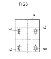
- the sealing element is executed in a variant of the invention as a sealing plate, which is essentially a same area (that is - apart from the height - same dimensions) and also a same hole pattern as the base plate has. It is possible that the opening cross section of the holes in the sealing plate from the opening cross section of the holes in the base plate deviates. However, this does not change the fundamentally identical hole pattern, which in particular results in an alignment of the holes in the sealing plate with holes in the base plate.
- the reinforcing element has a cross-sectionally C-shaped configuration.
- the open side of the C facing away from the traffic route, so pointing to the traffic route towards no sharp edges of the reinforcing element. A wheel of the vehicle touching the protective device is gently rejected, without getting caught in the reinforcing elements.
- the first post and the second post are arranged relative to each other such that the material-free region of the first post faces the second post.
- the material-free region of the second post also faces the first post. That is, a portion lying between the first and second posts is flanked on both sides by the material-free region of the first post and the material-free region of the second post.
- the first post is longer than the second post. That is, when a vehicle impacts on the guard and first bounces against the baffle, initially only the shorter second pillar is impacted with a corresponding impact energy.
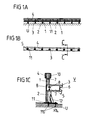
- the Figure 1A shows a side view of a section of a protective device with a plurality of first post 1 and a plurality of second posts 2, of which for clarity, only a few are provided with the corresponding reference numerals.
- a first post 1 and a second post 2 are arranged together on a common base plate 11 as a base plate by welding. This results in a plurality of pairs of posts, which are each mounted on a base plate 11. Furthermore, this results in an alternating sequence of first post 1 and second post 2.
- Each foot plate 11 is firmly anchored by means not shown anchors as fastening means in a substrate U.
- the spacers 5 serve not only the fixing and positioning of the guardrail 3, but in addition to receiving energy when a vehicle comes off the road and bounces against the guard.
- the aim is a relatively low effective range W (in particular W ⁇ 4), which with a protective device as in Figures 1A and 1B represented achieved.
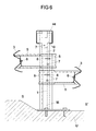
- the first post 1 is arranged.
- a bracket 10 is connected as a connecting element fixed to the first post 1.
- the bracket 10 has a slot 7, which is penetrated by a screw and the bracket 10 thus fixed to the first post 1.
- the upper portion of the bracket 10 is disposed in the interior of the box section 4 and is encompassed by this.
- the bracket 10 is attached to the first post 1 in such a way that the box profile 4 connected to the bracket 10 is flush with the upper edge of the first post 1.
- first segment 40 When the first segment 40 is inserted with its connecting portion 41 in the second segment 42, it is positioned so that the openings 7 and 8 of the individual segments 40 and 42 are aligned with each other. In this way, 7 screws can then be introduced into the openings, which connect the first segment 40 with the second segment 42.
- a third opening 9 is additionally arranged, through which a screw or other fastening means for fastening the guard rail 3 to the spacer 5 can be guided.
Landscapes
- Engineering & Computer Science (AREA)
- Architecture (AREA)
- Civil Engineering (AREA)
- Structural Engineering (AREA)
- Refuge Islands, Traffic Blockers, Or Guard Fence (AREA)
- Road Signs Or Road Markings (AREA)
Applications Claiming Priority (1)
| Application Number | Priority Date | Filing Date | Title |
|---|---|---|---|
| DE102007063511A DE102007063511B4 (de) | 2007-12-27 | 2007-12-27 | Schutzeinrichtung an Verkehrswegen |
Publications (2)
| Publication Number | Publication Date |
|---|---|
| EP2075377A2 true EP2075377A2 (fr) | 2009-07-01 |
| EP2075377A3 EP2075377A3 (fr) | 2010-04-28 |
Family
ID=40474186
Family Applications (1)
| Application Number | Title | Priority Date | Filing Date |
|---|---|---|---|
| EP08172057A Withdrawn EP2075377A3 (fr) | 2007-12-27 | 2008-12-18 | Dispositif de protection sur des voies de circulation |
Country Status (3)
| Country | Link |
|---|---|
| EP (1) | EP2075377A3 (fr) |
| DE (1) | DE102007063511B4 (fr) |
| IL (1) | IL196117A0 (fr) |
Cited By (4)
| Publication number | Priority date | Publication date | Assignee | Title |
|---|---|---|---|---|
| WO2012062415A1 (fr) * | 2010-11-09 | 2012-05-18 | Volkmann & Rossbach Gmbh & Co. Kg | Arrangement de poteau pour une construction de barrière de sécurité et construction de barrière de sécurité pour la sécurisation des voies de circulation sur des ouvrages |
| WO2012139931A1 (fr) * | 2011-04-15 | 2012-10-18 | Stahlwerk Annahütte Max Aicher GmbH & Co. KG | Système de guidage du trafic muni d'éléments raidisseurs |
| CN103089271A (zh) * | 2013-02-07 | 2013-05-08 | 中铁三局集团有限公司 | 大型箱涵顶拉法用分配梁组成及完成的施工方法 |
| EP4621129A1 (fr) * | 2024-03-18 | 2025-09-24 | Meiser Straßenausstattung GmbH | Profilé de coffre pour système de retenue de véhicule et procédé de fabrication de ce profilé de coffre |
Citations (3)
| Publication number | Priority date | Publication date | Assignee | Title |
|---|---|---|---|---|
| DE3813706A1 (de) * | 1988-04-22 | 1989-11-09 | Sps Schutzplanken Gmbh | Pfostenpaar fuer eine doppelleitplanke |
| DE10062648A1 (de) | 2000-12-15 | 2002-06-27 | Sps Schutzplanken Gmbh | Passive Rückhalteeinrichtung |
| DE202006013759U1 (de) | 2006-09-05 | 2006-11-16 | Outimex-Bautechnik Gmbh | Schutzeinrichtung an Verkehrswegen |
Family Cites Families (4)
| Publication number | Priority date | Publication date | Assignee | Title |
|---|---|---|---|---|
| DE2264431C3 (de) * | 1972-09-14 | 1975-06-12 | Karl 8750 Aschaffenburg Urlberger | Verankerungsvorrichtung von Geländern, Leitplanken o.dgl. in Brücken, StraBen o.dgl |
| DE29617846U1 (de) * | 1996-10-14 | 1997-02-06 | SPS Schutzplanken GmbH, 63743 Aschaffenburg | Pfostenanordnung für eine Schutzplanken aufweisende, passive Schutzeinrichtung |
| AT6416U3 (de) * | 2003-01-27 | 2004-02-25 | Voestalpine Krems Finaltechnik | Rückhaltesystem an fahrbahnrändern |
| ITTO20040060A1 (it) * | 2004-02-06 | 2004-05-06 | Fracasso Metalmeccanica | Barriera stradale |
-
2007
- 2007-12-27 DE DE102007063511A patent/DE102007063511B4/de not_active Expired - Fee Related
-
2008
- 2008-12-18 EP EP08172057A patent/EP2075377A3/fr not_active Withdrawn
- 2008-12-22 IL IL196117A patent/IL196117A0/en unknown
Patent Citations (3)
| Publication number | Priority date | Publication date | Assignee | Title |
|---|---|---|---|---|
| DE3813706A1 (de) * | 1988-04-22 | 1989-11-09 | Sps Schutzplanken Gmbh | Pfostenpaar fuer eine doppelleitplanke |
| DE10062648A1 (de) | 2000-12-15 | 2002-06-27 | Sps Schutzplanken Gmbh | Passive Rückhalteeinrichtung |
| DE202006013759U1 (de) | 2006-09-05 | 2006-11-16 | Outimex-Bautechnik Gmbh | Schutzeinrichtung an Verkehrswegen |
Cited By (5)
| Publication number | Priority date | Publication date | Assignee | Title |
|---|---|---|---|---|
| WO2012062415A1 (fr) * | 2010-11-09 | 2012-05-18 | Volkmann & Rossbach Gmbh & Co. Kg | Arrangement de poteau pour une construction de barrière de sécurité et construction de barrière de sécurité pour la sécurisation des voies de circulation sur des ouvrages |
| EP2455546A1 (fr) * | 2010-11-09 | 2012-05-23 | Volkmann & Rossbach GmbH & Co. KG | Agencement de poteau pour une construction de glissière de sécurité et construction de glissière de sécurité pour sécuriser des bandes de roulement sur des chantiers |
| WO2012139931A1 (fr) * | 2011-04-15 | 2012-10-18 | Stahlwerk Annahütte Max Aicher GmbH & Co. KG | Système de guidage du trafic muni d'éléments raidisseurs |
| CN103089271A (zh) * | 2013-02-07 | 2013-05-08 | 中铁三局集团有限公司 | 大型箱涵顶拉法用分配梁组成及完成的施工方法 |
| EP4621129A1 (fr) * | 2024-03-18 | 2025-09-24 | Meiser Straßenausstattung GmbH | Profilé de coffre pour système de retenue de véhicule et procédé de fabrication de ce profilé de coffre |
Also Published As
| Publication number | Publication date |
|---|---|
| DE102007063511B4 (de) | 2011-08-25 |
| DE102007063511A1 (de) | 2009-07-09 |
| IL196117A0 (en) | 2009-09-22 |
| EP2075377A3 (fr) | 2010-04-28 |
Similar Documents
| Publication | Publication Date | Title |
|---|---|---|
| AT390979B (de) | Schutzplankenanordnung | |
| EP2455546B1 (fr) | Agencement de poteau pour une construction de glissière de sécurité et construction de glissière de sécurité pour sécuriser des bandes de roulement sur des chantiers | |
| EP1762660B1 (fr) | Dispositif de guidage routier | |
| EP1650351B1 (fr) | Poteau pour glissières de sécurité | |
| DE102007063511B4 (de) | Schutzeinrichtung an Verkehrswegen | |
| DE202012104881U1 (de) | Barriereelement und Barriere aus zumindest zwei miteinander verbundenen Barriereelementen | |
| EP3827128B1 (fr) | Système de retenue de véhicule avec montant | |
| EP1816263B1 (fr) | Dispositif de guidage routier | |
| EP2900873A1 (fr) | Élément de délimitation de surfaces de circulation | |
| EP1997957B1 (fr) | Système de retenue pour véhicule sur voirie | |
| WO2011066973A1 (fr) | Construction de barrière de sécurité | |
| EP1898002B1 (fr) | Dispositif de protection sur voies de circulation | |
| EP2567030B1 (fr) | Glissière de sécurité | |
| EP2034094B1 (fr) | Dispositif conducteur sur des trajectoires de trafic doté de deux systèmes de retenue à raideur différente et d'une construction de passage entre ceux-ci | |
| DE102009028904A1 (de) | Leitplanke oder Schutzplanke, bestehend aus einem einzigen Element oder aus mehreren in Längsrichtung aneinandergekoppelten Elementen | |
| EP0761889B1 (fr) | Disposition de barrière routière | |
| DE10356220A1 (de) | Sicherungseinrichtung für befahrbare oder begehbare Flächen | |
| DE102008048810A1 (de) | Verkehrs-Leit-Einrichtung | |
| EP1619310A1 (fr) | Glissière de sécurité pour un système de retenue d'un véhicule | |
| WO2022161839A1 (fr) | Élément paroi formant barrière | |
| WO2012139931A1 (fr) | Système de guidage du trafic muni d'éléments raidisseurs | |
| DE20317824U1 (de) | Gleitwand für Verkehrswege | |
| DE102009044721B4 (de) | Schutzplanksystem zur Absicherung von Gefahrenstellen durch Objekte am Fahrbahnrand | |
| EP1876300A1 (fr) | Barrière de sécurité d'acier | |
| DE102008056807A1 (de) | Fahrbahnbegrenzung mit Wechsel zwischen zwei Rückhaltesystemen unterschiedlicher Nachgiebigkeit |
Legal Events
| Date | Code | Title | Description |
|---|---|---|---|
| PUAI | Public reference made under article 153(3) epc to a published international application that has entered the european phase |
Free format text: ORIGINAL CODE: 0009012 |
|
| AK | Designated contracting states |
Kind code of ref document: A2 Designated state(s): AT BE BG CH CY CZ DE DK EE ES FI FR GB GR HR HU IE IS IT LI LT LU LV MC MT NL NO PL PT RO SE SI SK TR |
|
| AX | Request for extension of the european patent |
Extension state: AL BA MK RS |
|
| PUAL | Search report despatched |
Free format text: ORIGINAL CODE: 0009013 |
|
| AK | Designated contracting states |
Kind code of ref document: A3 Designated state(s): AT BE BG CH CY CZ DE DK EE ES FI FR GB GR HR HU IE IS IT LI LT LU LV MC MT NL NO PL PT RO SE SI SK TR |
|
| AX | Request for extension of the european patent |
Extension state: AL BA MK RS |
|
| 17P | Request for examination filed |
Effective date: 20101022 |
|
| AKX | Designation fees paid |
Designated state(s): AT BE BG CH CY CZ DE DK EE ES FI FR GB GR HR HU IE IS IT LI LT LU LV MC MT NL NO PL PT RO SE SI SK TR |
|
| 17Q | First examination report despatched |
Effective date: 20110128 |
|
| RAP1 | Party data changed (applicant data changed or rights of an application transferred) |
Owner name: SAFEROAD RRS GMBH |
|
| GRAP | Despatch of communication of intention to grant a patent |
Free format text: ORIGINAL CODE: EPIDOSNIGR1 |
|
| STAA | Information on the status of an ep patent application or granted ep patent |
Free format text: STATUS: THE APPLICATION IS DEEMED TO BE WITHDRAWN |
|
| 18D | Application deemed to be withdrawn |
Effective date: 20130326 |