EP2075384A2 - Elément d'entretoise pour le montage de dispositifs destinés à la tension de pièces usinées - Google Patents
Elément d'entretoise pour le montage de dispositifs destinés à la tension de pièces usinées Download PDFInfo
- Publication number
- EP2075384A2 EP2075384A2 EP08169005A EP08169005A EP2075384A2 EP 2075384 A2 EP2075384 A2 EP 2075384A2 EP 08169005 A EP08169005 A EP 08169005A EP 08169005 A EP08169005 A EP 08169005A EP 2075384 A2 EP2075384 A2 EP 2075384A2
- Authority
- EP
- European Patent Office
- Prior art keywords
- strut
- shaped
- extension
- slot
- strut element
- Prior art date
- Legal status (The legal status is an assumption and is not a legal conclusion. Google has not performed a legal analysis and makes no representation as to the accuracy of the status listed.)
- Withdrawn
Links
- 238000010276 construction Methods 0.000 claims description 7
- 229910000838 Al alloy Inorganic materials 0.000 claims description 4
- 229910052782 aluminium Inorganic materials 0.000 claims description 4
- XAGFODPZIPBFFR-UHFFFAOYSA-N aluminium Chemical compound [Al] XAGFODPZIPBFFR-UHFFFAOYSA-N 0.000 claims description 4
- 229910052751 metal Inorganic materials 0.000 claims description 4
- 239000002184 metal Substances 0.000 claims description 4
- 229910001092 metal group alloy Inorganic materials 0.000 claims description 2
- 238000003780 insertion Methods 0.000 description 5
- 230000037431 insertion Effects 0.000 description 5
- 238000003754 machining Methods 0.000 description 4
- 238000004519 manufacturing process Methods 0.000 description 4
- 238000003801 milling Methods 0.000 description 3
- 238000011161 development Methods 0.000 description 2
- 230000018109 developmental process Effects 0.000 description 2
- 238000004026 adhesive bonding Methods 0.000 description 1
- 230000015572 biosynthetic process Effects 0.000 description 1
- 238000005520 cutting process Methods 0.000 description 1
- 230000001419 dependent effect Effects 0.000 description 1
- 238000013461 design Methods 0.000 description 1
- 238000005553 drilling Methods 0.000 description 1
- 238000001125 extrusion Methods 0.000 description 1
- 238000009499 grossing Methods 0.000 description 1
- 238000009434 installation Methods 0.000 description 1
- 238000005304 joining Methods 0.000 description 1
- 239000000463 material Substances 0.000 description 1
- 238000002360 preparation method Methods 0.000 description 1
- 238000012545 processing Methods 0.000 description 1
- 238000003908 quality control method Methods 0.000 description 1
Images




Classifications
-
- E—FIXED CONSTRUCTIONS
- E04—BUILDING
- E04B—GENERAL BUILDING CONSTRUCTIONS; WALLS, e.g. PARTITIONS; ROOFS; FLOORS; CEILINGS; INSULATION OR OTHER PROTECTION OF BUILDINGS
- E04B1/00—Constructions in general; Structures which are not restricted either to walls, e.g. partitions, or floors or ceilings or roofs
- E04B1/38—Connections for building structures in general
- E04B1/58—Connections for building structures in general of bar-shaped building elements
- E04B1/5825—Connections for building structures in general of bar-shaped building elements with a closed cross-section
- E04B1/5831—Connections for building structures in general of bar-shaped building elements with a closed cross-section of substantially rectangular form
-
- B—PERFORMING OPERATIONS; TRANSPORTING
- B23—MACHINE TOOLS; METAL-WORKING NOT OTHERWISE PROVIDED FOR
- B23Q—DETAILS, COMPONENTS, OR ACCESSORIES FOR MACHINE TOOLS, e.g. ARRANGEMENTS FOR COPYING OR CONTROLLING; MACHINE TOOLS IN GENERAL CHARACTERISED BY THE CONSTRUCTION OF PARTICULAR DETAILS OR COMPONENTS; COMBINATIONS OR ASSOCIATIONS OF METAL-WORKING MACHINES, NOT DIRECTED TO A PARTICULAR RESULT
- B23Q3/00—Devices holding, supporting, or positioning work or tools, of a kind normally removable from the machine
- B23Q3/02—Devices holding, supporting, or positioning work or tools, of a kind normally removable from the machine for mounting on a work-table, tool-slide, or analogous part
- B23Q3/10—Auxiliary devices, e.g. bolsters, extension members
- B23Q3/103—Constructional elements used for constructing work holders
-
- E—FIXED CONSTRUCTIONS
- E04—BUILDING
- E04B—GENERAL BUILDING CONSTRUCTIONS; WALLS, e.g. PARTITIONS; ROOFS; FLOORS; CEILINGS; INSULATION OR OTHER PROTECTION OF BUILDINGS
- E04B1/00—Constructions in general; Structures which are not restricted either to walls, e.g. partitions, or floors or ceilings or roofs
- E04B1/38—Connections for building structures in general
- E04B1/541—Joints substantially without separate connecting elements, e.g. jointing by inter-engagement
-
- E—FIXED CONSTRUCTIONS
- E04—BUILDING
- E04B—GENERAL BUILDING CONSTRUCTIONS; WALLS, e.g. PARTITIONS; ROOFS; FLOORS; CEILINGS; INSULATION OR OTHER PROTECTION OF BUILDINGS
- E04B1/00—Constructions in general; Structures which are not restricted either to walls, e.g. partitions, or floors or ceilings or roofs
- E04B1/38—Connections for building structures in general
- E04B1/58—Connections for building structures in general of bar-shaped building elements
-
- E—FIXED CONSTRUCTIONS
- E04—BUILDING
- E04B—GENERAL BUILDING CONSTRUCTIONS; WALLS, e.g. PARTITIONS; ROOFS; FLOORS; CEILINGS; INSULATION OR OTHER PROTECTION OF BUILDINGS
- E04B1/00—Constructions in general; Structures which are not restricted either to walls, e.g. partitions, or floors or ceilings or roofs
- E04B1/38—Connections for building structures in general
- E04B1/58—Connections for building structures in general of bar-shaped building elements
- E04B1/5825—Connections for building structures in general of bar-shaped building elements with a closed cross-section
- E04B1/5837—Connections for building structures in general of bar-shaped building elements with a closed cross-section of substantially circular form
- E04B1/5843—Connections for building structures in general of bar-shaped building elements with a closed cross-section of substantially circular form with ends provided with protuberances
-
- E—FIXED CONSTRUCTIONS
- E04—BUILDING
- E04B—GENERAL BUILDING CONSTRUCTIONS; WALLS, e.g. PARTITIONS; ROOFS; FLOORS; CEILINGS; INSULATION OR OTHER PROTECTION OF BUILDINGS
- E04B2/00—Walls, e.g. partitions, for buildings; Wall construction with regard to insulation; Connections specially adapted to walls
- E04B2/74—Removable non-load-bearing partitions; Partitions with a free upper edge
- E04B2/76—Removable non-load-bearing partitions; Partitions with a free upper edge with framework or posts of metal
- E04B2/766—T-connections
-
- E—FIXED CONSTRUCTIONS
- E04—BUILDING
- E04B—GENERAL BUILDING CONSTRUCTIONS; WALLS, e.g. PARTITIONS; ROOFS; FLOORS; CEILINGS; INSULATION OR OTHER PROTECTION OF BUILDINGS
- E04B2/00—Walls, e.g. partitions, for buildings; Wall construction with regard to insulation; Connections specially adapted to walls
- E04B2/74—Removable non-load-bearing partitions; Partitions with a free upper edge
- E04B2/76—Removable non-load-bearing partitions; Partitions with a free upper edge with framework or posts of metal
- E04B2/78—Removable non-load-bearing partitions; Partitions with a free upper edge with framework or posts of metal characterised by special cross-section of the frame members as far as important for securing wall panels to a framework with or without the help of cover-strips
- E04B2/7809—Removable non-load-bearing partitions; Partitions with a free upper edge with framework or posts of metal characterised by special cross-section of the frame members as far as important for securing wall panels to a framework with or without the help of cover-strips of single or multiple tubular form
- E04B2/7818—Removable non-load-bearing partitions; Partitions with a free upper edge with framework or posts of metal characterised by special cross-section of the frame members as far as important for securing wall panels to a framework with or without the help of cover-strips of single or multiple tubular form of substantially rectangular form
-
- F—MECHANICAL ENGINEERING; LIGHTING; HEATING; WEAPONS; BLASTING
- F16—ENGINEERING ELEMENTS AND UNITS; GENERAL MEASURES FOR PRODUCING AND MAINTAINING EFFECTIVE FUNCTIONING OF MACHINES OR INSTALLATIONS; THERMAL INSULATION IN GENERAL
- F16B—DEVICES FOR FASTENING OR SECURING CONSTRUCTIONAL ELEMENTS OR MACHINE PARTS TOGETHER, e.g. NAILS, BOLTS, CIRCLIPS, CLAMPS, CLIPS OR WEDGES; JOINTS OR JOINTING
- F16B7/00—Connections of rods or tubes, e.g. of non-circular section, mutually, including resilient connections
- F16B7/04—Clamping or clipping connections
- F16B7/044—Clamping or clipping connections for rods or tubes being in angled relationship
- F16B7/0446—Clamping or clipping connections for rods or tubes being in angled relationship for tubes using the innerside thereof
- F16B7/0473—Clamping or clipping connections for rods or tubes being in angled relationship for tubes using the innerside thereof with hook-like parts gripping, e.g. by expanding, behind the flanges of a profile
Definitions
- the invention relates to a strut element for the construction of devices for clamping of in particular complex shaped workpieces.
- Such strut elements are well known and in large variety. They find particular application in the construction of jigs for workpieces with more complex, three-dimensional shapes such as automotive sheet metal parts, complex shaped parts for aircraft production and the like. In particular, these devices are used for accurate clamping of such parts for the purpose of surveying, be it for prototype construction, be it for the quality control of an ongoing production.
- struts From such struts are constructed as jigs device-like devices in which then at predetermined points in space holding devices, such as clamping elements and the like are arranged.
- space holding devices such as clamping elements and the like are arranged.
- Such a system which has proven itself on the market for many years, is offered on the market under the brand name "Alufix”.
- This system is a very flexible and, in particular, recyclable system, in which connecting elements can be inserted by means of pass-hole bores arranged at predetermined intervals and the individual strut elements can be flexibly connected to one another.
- the invention seeks to remedy this situation.
- This object is achieved according to the invention by a strut element with the features of claim 1.
- Advantageous developments of the invention are specified in the dependent claims 2 to 7.
- a strut element is thus formed so that it has at least one end face a connection structure which is integrally formed.
- This connection structure is formed either by a T-slot or alternatively by a corresponding to such a T-slot T-shaped, pin-like extension.
- the strut element according to the invention can be very simple and elegant either with other, equipped on its front side with corresponding connection structures strut elements frontally or with other elements on other surfaces, the corresponding T-slots or T-shaped, pin-like Have extensions.
- the connecting structures, T-slot or T-shaped, pin-like extension can be formed, for example, by machining processes, in particular milling, on one or both end sides of the strut element.
- the strut element can have any conceivable shape, wherein a cost-effective strut element to be produced from an extruded profile is to be preferred.
- the strut element may have smooth surfaces on its longitudinal sides or its longitudinal periphery, for example in order to serve as scaffold-reinforcing diagonal strut, but it may also and in particular have a T-groove on at least one side surface formed on the end face like a T-slot of the connection structure. which then typically extends in the longitudinal direction of the strut element.
- This has the advantage that such a strut element is flexibly connectable with further identically formed strut elements.
- a strut element having four side surfaces with T-slots of this type in all four side surfaces.
- a strut element according to the invention has a connection structure according to the invention in the form of a T-groove or a T-shaped, pin-like extension on only one of its end faces, the strut elements according to the invention become in the vast majority of cases contain corresponding connection structures on both end faces. It basically does not matter and depends solely on the application in the construction of the device, whether at both ends about T-slots or T-shaped, pin-like extensions are formed or on one end face a T-slot, on the other a T shaped, cone-like extension.
- connecting directions of the arranged at the two end faces connecting structures ie the longitudinal direction of the T-shaped, peg-like extension or the direction of the T-slot selected parallel or perpendicular to each other can be.
- the strut elements according to the invention consist of a light metal or of a light metal alloy, in particular aluminum or an aluminum alloy.
- the strut elements according to the invention are particularly suitable for a one-off, fixed predetermined construction of a jig for workpieces by glued together after joining T-slot and T-shaped, pin-like extension in the desired position or by other means, eg by screwing, locked and fixed become.
- strut elements according to the invention can also be “finished" by such smoothing and deburring being carried out, in particular when multiple usability of the strut elements is intended and intended.
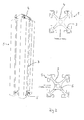
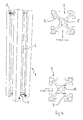
- FIGS. 1 to 8 Strut elements 1, which are based on a substantially square in cross section basic profile with all sides in the longitudinal direction of the struts extending T-slots 3, is in FIG. 9 an inventive strut element 2 shown, which was made of a smooth-walled profile element with a round cross-section.
- strut elements 1 is common that they at both opposite end faces each connecting structures in the form of either T-shaped, pin-like extensions 4 or arranged there T Have grooves 5.
- the T-slots 5 correspond in their profile to the T-slots 3, the T-shaped, pin-like extensions 4 are formed corresponding to the profile of the T-slots 5 and 3 and can connect the individual elements in one or both of these T-slots 3 and 5 intervene.
- the connecting structures on the end faces of the strut elements 1, the T-shaped, pin-like extensions 4 and the T-slots 5, are integrally formed from the material of the strut element, preferably by machining, in particular milling.
- the strut elements 1, but also 2, which are preferably made of aluminum or an aluminum alloy, are particularly well suited for such a machining, so that the connection structures in the form of T-grooves 5 and T-shaped, pin-like extensions 4 means Such a processing can be easily and inexpensively attached.
- FIGS. 1 to 8 illustrated strut elements 1 according to the invention by the combination and respective arrangement of the connection structures.
- a strut element 1 shown, which has on the opposite end faces on the one hand a T-shaped, pin-like extension 4, on the other hand, a T-groove 5.
- a similarly constructed strut element 1 is shown, in which, however, the course directions of the extension 4 and the T-slot 5 are rotated by 90 ° to each other, which is made clear by the arrows of the insertion directions.
- Struts 1 are shown with arranged on both end faces T-slots 5, in FIG. 3 with parallel and in FIG. 4 with 90 ° offset course or insertion directions.
- Struts 1 are shown in an analogous manner with integrally formed on both end extensions 4, in FIG. 5 with parallel directions, in FIG. 6 rotated by 90 °.
- FIGS. 7 and 8th By way of example strut elements 1 shown with obliquely cut connection surfaces, here approximately at an angle of 45 ° to the longitudinal direction. These allow an obliquely running in the room or diagonal installation direction. Shown here are in FIG. 7 on the one hand arranged on the oblique front side extension 4, on the other hand in FIG. 8 a T-slot 5 arranged there.
- the insertion directions of the connecting structures seated on the obliquely cut connecting surface are offset by 90 ° relative to the insertion direction of the connecting face cut on a straight (at 90 ° to the longitudinal direction) on the opposite end face arranged T-groove 5.
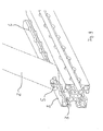
- inventive strut element 2 is shown, which is provided on one end face with a T-groove 5.
- This strut element 2 which also made An extrusion profile is made of aluminum and an aluminum alloy, has a circular cross section and a smooth shell surface.
- the end face provided with the T-groove 5 is cut obliquely to the longitudinal direction of the strut element 2, so that this element can serve as a diagonal strut.
- this element is placed on a conventional strut element S with untreated end faces, which in turn carries T-grooves 3 on its side surfaces 3.
- This element can be connected for example by a connector in the form of a double-T.
- bores 6 are additionally introduced in grid intervals in the T-slot 3, which can serve the connection with other attachments.
- the exemplary embodiments illustrated here merely show an overview of the manifold possibilities for designing strut elements according to the invention.
- the strut elements 1 can also be provided on one side only with a connecting structure in the form of an extension 4 or a T-slot 5.
- Other outer shapes of the strut elements are conceivable, as are other combinations of connection structures in the form of extensions 4 and T-slots 5.
- connection structures in the form of the extensions 4 and T-slots 5 can be connected by gluing to each other or screwed together.
Landscapes
- Engineering & Computer Science (AREA)
- Architecture (AREA)
- Physics & Mathematics (AREA)
- Electromagnetism (AREA)
- Civil Engineering (AREA)
- Structural Engineering (AREA)
- Mechanical Engineering (AREA)
- Mutual Connection Of Rods And Tubes (AREA)
- Clamps And Clips (AREA)
Applications Claiming Priority (1)
| Application Number | Priority Date | Filing Date | Title |
|---|---|---|---|
| DE202007016844U DE202007016844U1 (de) | 2007-11-30 | 2007-11-30 | Strebeelement für den Aufbau von Vorrichtungen zum Aufspannen von Werkstücken |
Publications (2)
| Publication Number | Publication Date |
|---|---|
| EP2075384A2 true EP2075384A2 (fr) | 2009-07-01 |
| EP2075384A3 EP2075384A3 (fr) | 2011-11-16 |
Family
ID=39198834
Family Applications (1)
| Application Number | Title | Priority Date | Filing Date |
|---|---|---|---|
| EP08169005A Withdrawn EP2075384A3 (fr) | 2007-11-30 | 2008-11-13 | Elément d'entretoise pour le montage de dispositifs destinés à la tension de pièces usinées |
Country Status (2)
| Country | Link |
|---|---|
| EP (1) | EP2075384A3 (fr) |
| DE (1) | DE202007016844U1 (fr) |
Citations (2)
| Publication number | Priority date | Publication date | Assignee | Title |
|---|---|---|---|---|
| DE4132655A1 (de) | 1991-10-01 | 1993-04-08 | Wolfgang Pagel | Vorrichtung zum positionieren eines objektes, beispielsweise eines werkstueckes |
| WO2001008855A1 (fr) | 1999-07-29 | 2001-02-08 | Amg | Prehenseur modulaire |
Family Cites Families (3)
| Publication number | Priority date | Publication date | Assignee | Title |
|---|---|---|---|---|
| DE316958C (fr) * | ||||
| FR1531524A (fr) * | 1967-05-22 | 1968-07-05 | Plastival S A | Profilé |
| DE8816884U1 (de) * | 1988-01-12 | 1991-02-07 | Octanorm-Vertriebs-GmbH für Bauelemente, 7024 Filderstadt | Tragstange mit einem Verbindungsknoten |
-
2007
- 2007-11-30 DE DE202007016844U patent/DE202007016844U1/de not_active Expired - Lifetime
-
2008
- 2008-11-13 EP EP08169005A patent/EP2075384A3/fr not_active Withdrawn
Patent Citations (2)
| Publication number | Priority date | Publication date | Assignee | Title |
|---|---|---|---|---|
| DE4132655A1 (de) | 1991-10-01 | 1993-04-08 | Wolfgang Pagel | Vorrichtung zum positionieren eines objektes, beispielsweise eines werkstueckes |
| WO2001008855A1 (fr) | 1999-07-29 | 2001-02-08 | Amg | Prehenseur modulaire |
Also Published As
| Publication number | Publication date |
|---|---|
| DE202007016844U1 (de) | 2008-03-20 |
| EP2075384A3 (fr) | 2011-11-16 |
Similar Documents
| Publication | Publication Date | Title |
|---|---|---|
| DE102005057397A1 (de) | Mehrzweckprofile für den Zusammenbau von Rahmen, Haltevorrichtungen, tragenden Teilen und ähnlichem | |
| EP0237768B1 (fr) | Dispositif d'assemblage spatial d'éléments | |
| EP1977124A1 (fr) | Dispositif pour maintenir et positionner des appareils, des pièces et des outils | |
| EP2468985B1 (fr) | Dispositif de revêtement de sol pour systèmes de scènes, de tribunes ou de podiums | |
| DE3829998A1 (de) | Verbindungsstueck fuer die parallelverbindung von profilen | |
| DE102005007441B4 (de) | Prüflehrenvorrichtung und Lehrenkörper | |
| EP4221936B1 (fr) | Plaque avec au moins une fente dans sa surface et écrou à fente | |
| EP2075384A2 (fr) | Elément d'entretoise pour le montage de dispositifs destinés à la tension de pièces usinées | |
| EP1640621A1 (fr) | Pièce de barre ou d'armature avec la coupe transversale rectangulaire pour un système à la construction des dispositifs fixent des objets | |
| EP3244076A1 (fr) | Élément de liaison de barres de retenue dans un bus | |
| EP3170595B1 (fr) | Porte-outil | |
| DE60121338T2 (de) | Verfahren und vorrichtung zum befestigen eines kolbens oder einer kolbenstangeverbindung an einer kolbenstange | |
| DE202019102022U1 (de) | Modularer Bausatz zum Aufbau von dreidimensionalen Strukturen für die Aufnahme von Werkstücken | |
| DE202012008659U1 (de) | Lösbare Verbindung zwischen T-förmig aufeinandertreffenden Profilen | |
| DE202007007888U1 (de) | Element und System zum Aufbau von Vorrichtungen zum Aufspannen von Werkstücken | |
| DE60300443T2 (de) | Schraubenverbindung, insbesondere für geschlitzte Profilschienen | |
| DE202009009344U1 (de) | Verbindungsvorrichtung für Profile | |
| EP3564543B1 (fr) | Procédé et systéme de fixation à vis d'un composant pourvu de canal à vis | |
| DE20315497U1 (de) | Vorrichtung zur Aufnahme von Werkstücken | |
| DE102017123543B4 (de) | Regalsystem und Steckeinsatz zur Verbindung von Streben eines Regalsystems | |
| DE102015211849A1 (de) | Sandwichelement | |
| DE20315498U1 (de) | Winkelprofilelement als Ausgangselement zum Aufbau von Vorrichtungen zur Aufnahme von Werkstücken | |
| DE102016004341B4 (de) | Verbindungselement zur Verbindung von Haltestangen in einem Bus | |
| DE202011000486U1 (de) | Basisleistenprofil | |
| DE202015101467U1 (de) | Baukastensystem zum Aufbau von Vorrichtungen zum Aufspannen von Werkstücken |
Legal Events
| Date | Code | Title | Description |
|---|---|---|---|
| PUAI | Public reference made under article 153(3) epc to a published international application that has entered the european phase |
Free format text: ORIGINAL CODE: 0009012 |
|
| AK | Designated contracting states |
Kind code of ref document: A2 Designated state(s): AT BE BG CH CY CZ DE DK EE ES FI FR GB GR HR HU IE IS IT LI LT LU LV MC MT NL NO PL PT RO SE SI SK TR |
|
| AX | Request for extension of the european patent |
Extension state: AL BA MK RS |
|
| PUAL | Search report despatched |
Free format text: ORIGINAL CODE: 0009013 |
|
| AK | Designated contracting states |
Kind code of ref document: A3 Designated state(s): AT BE BG CH CY CZ DE DK EE ES FI FR GB GR HR HU IE IS IT LI LT LU LV MC MT NL NO PL PT RO SE SI SK TR |
|
| AX | Request for extension of the european patent |
Extension state: AL BA MK RS |
|
| RIC1 | Information provided on ipc code assigned before grant |
Ipc: E04B 2/76 20060101ALI20111012BHEP Ipc: F16B 7/04 20060101ALI20111012BHEP Ipc: E04B 2/78 20060101ALI20111012BHEP Ipc: E04B 1/58 20060101AFI20111012BHEP |
|
| STAA | Information on the status of an ep patent application or granted ep patent |
Free format text: STATUS: THE APPLICATION HAS BEEN WITHDRAWN |
|
| 18W | Application withdrawn |
Effective date: 20111123 |