EP2075415A1 - Ringstruktur des Stators in leichterer Ausführung für das Triebwerk eines Luftfahrzeugs - Google Patents
Ringstruktur des Stators in leichterer Ausführung für das Triebwerk eines Luftfahrzeugs Download PDFInfo
- Publication number
- EP2075415A1 EP2075415A1 EP20070124098 EP07124098A EP2075415A1 EP 2075415 A1 EP2075415 A1 EP 2075415A1 EP 20070124098 EP20070124098 EP 20070124098 EP 07124098 A EP07124098 A EP 07124098A EP 2075415 A1 EP2075415 A1 EP 2075415A1
- Authority
- EP
- European Patent Office
- Prior art keywords
- ferrule
- stator
- annular
- sector
- turbine engine
- Prior art date
- Legal status (The legal status is an assumption and is not a legal conclusion. Google has not performed a legal analysis and makes no representation as to the accuracy of the status listed.)
- Granted
Links
Images





Classifications
-
- F—MECHANICAL ENGINEERING; LIGHTING; HEATING; WEAPONS; BLASTING
- F01—MACHINES OR ENGINES IN GENERAL; ENGINE PLANTS IN GENERAL; STEAM ENGINES
- F01D—NON-POSITIVE DISPLACEMENT MACHINES OR ENGINES, e.g. STEAM TURBINES
- F01D9/00—Stators
- F01D9/02—Nozzles; Nozzle boxes; Stator blades; Guide conduits, e.g. individual nozzles
- F01D9/04—Nozzles; Nozzle boxes; Stator blades; Guide conduits, e.g. individual nozzles forming ring or sector
- F01D9/042—Nozzles; Nozzle boxes; Stator blades; Guide conduits, e.g. individual nozzles forming ring or sector fixing blades to stators
-
- F—MECHANICAL ENGINEERING; LIGHTING; HEATING; WEAPONS; BLASTING
- F01—MACHINES OR ENGINES IN GENERAL; ENGINE PLANTS IN GENERAL; STEAM ENGINES
- F01D—NON-POSITIVE DISPLACEMENT MACHINES OR ENGINES, e.g. STEAM TURBINES
- F01D5/00—Blades; Blade-carrying members; Heating, heat-insulating, cooling or antivibration means on the blades or the members
- F01D5/12—Blades
- F01D5/26—Antivibration means not restricted to blade form or construction or to blade-to-blade connections or to the use of particular materials
-
- F—MECHANICAL ENGINEERING; LIGHTING; HEATING; WEAPONS; BLASTING
- F05—INDEXING SCHEMES RELATING TO ENGINES OR PUMPS IN VARIOUS SUBCLASSES OF CLASSES F01-F04
- F05D—INDEXING SCHEME FOR ASPECTS RELATING TO NON-POSITIVE-DISPLACEMENT MACHINES OR ENGINES, GAS-TURBINES OR JET-PROPULSION PLANTS
- F05D2260/00—Function
- F05D2260/96—Preventing, counteracting or reducing vibration or noise
-
- Y—GENERAL TAGGING OF NEW TECHNOLOGICAL DEVELOPMENTS; GENERAL TAGGING OF CROSS-SECTIONAL TECHNOLOGIES SPANNING OVER SEVERAL SECTIONS OF THE IPC; TECHNICAL SUBJECTS COVERED BY FORMER USPC CROSS-REFERENCE ART COLLECTIONS [XRACs] AND DIGESTS
- Y02—TECHNOLOGIES OR APPLICATIONS FOR MITIGATION OR ADAPTATION AGAINST CLIMATE CHANGE
- Y02T—CLIMATE CHANGE MITIGATION TECHNOLOGIES RELATED TO TRANSPORTATION
- Y02T50/00—Aeronautics or air transport
- Y02T50/60—Efficient propulsion technologies, e.g. for aircraft
Definitions
- the present invention relates generally to an aircraft turbine engine, preferably of the turbojet or turboprop type.
- the invention relates to an annular stator structure for a module of such a turbine engine, comprising a ferrule for delimiting radially inward a primary flow through the turbine engine.
- the ferrule also called said inner ferrule, has in known manner a section in the overall shape of U, said U reversed because of the fact that the two branches of the U extend substantially in a radially inner direction from the base of this U , whose outer surface is matched by the aforementioned primary flow.
- a ferrule is for example known from the document FR 2 404 102 .
- the inner ferrule which can also act as a vibration damper, is arranged on the wall internal of the ferrule, and usually fills each aperture to limit the vibrations undergone by the stator vanes, in operation.
- the aforementioned annular structure therefore comprises the shell equipped with a radially inner coating forming an annular sealing strip intended to be contacted by a rotating part of the turbine engine, and attached to the shell.
- this so-called abradable coating is generally contacted by a sealing device carried by the rotor associated with the stator concerned, such a sealing device being described as a labyrinth or a wiper device.
- the object of the invention is therefore to propose an annular stator structure for a turbine engine module at least partially remedying the problem mentioned above, relating to the embodiments of the prior art.
- the subject of the invention is an annular stator structure for an aircraft turbine engine module, said structure comprising a stator shroud intended to delimit radially inwards a primary flow passing through said turbine engine, said ferrule comprising a plurality apertures each for receiving the foot of a stator vane, said annular structure further comprising a radially inner liner forming annular sealing track and made of a first material, said radially inner liner being intended to be contacted by a rotating part of said turbine engine, and attached to said ferrule.
- the annular structure further comprises, interposed between said ferrule and said inner liner, filling means made of a second material having a density lower than that of said first material.
- the annular structure according to the invention advantageously has a weakened mass compared to the embodiments of the prior art, since part of the radially inner coating is replaced by the filling means of lower density.
- These filling means may extend over all or part of the circumferential length of the annular structure, always between the ferrule and the radially inner liner, the latter alone making it possible to form the sealing lane.
- said second material is foam, preferably non-metallic, and closed-cell, such as polymethacrylimide rigid foam.
- the ratio between the densities of the first and second materials is less than 0.1.
- said filling means are interposed between said ferrule and said lining sealing lane, over all or part of the circumferential length.
- the filling means therefore extend circumferentially in an interrupted manner, for example between the blade roots passing through the openings of the ferrule of the annular structure.
- the filling means extend over the entire periphery of the annular structure, forming a ring of light material, preferably in fixed contact with the perforated ferrule.
- said ferrule has a section of overall U-shape, the two branches of the U extending substantially in a radially inner direction from the base of this U, said ferrule comprising a plurality of openings each intended to receive the foot of a stator blade, each aperture being made through said base of the U.
- said ferrule has a section of generally open shape in the inner radial direction, and comprising a base of delimitation of the primary flow, said ferrule comprising a plurality of apertures each intended to receive the foot. a stator blade, each a journey being practiced through said base.
- other shapes than the U are possible for the open section radially inward, without departing from the scope of the invention. AT As an illustrative example, it can be deleted the downstream branch of the U.
- the filling means are preferably arranged on the inner surface of the base of the U, that is to say the one opposite the delimiting surface of the primary flow.
- each aperture is for example extended by stiffening means of the ferrule projecting from said base of the U, substantially in said inner radial direction, said stiffening means take the form of a rib extending over substantially all around the opening it defines.
- this embodiment is remarkable in that each a journey no longer only extends over the thickness of the base of the U, but is extended radially inwardly by projecting means simultaneously serving to stiffen the ferrule.
- the use of materials other than metal materials can thus be envisaged, thanks to the rigidity provided by the addition of these stiffening means.
- the use of a composite material therefore becomes possible, which provides a real advantage in terms of mass, particularly compared to metal solutions known from the prior art.
- stiffening means form physical barriers between the openings, thus facilitating the subsequent introduction of elements in the spaces formed by these barriers, such as the filling means, as will be explained below.
- each rib preferably follows a closed line corresponding to the periphery of the aperture, the latter therefore being constituted firstly by means of the opening made in the base of the U of the ferrule, and of on the other hand, by the closed rib defining internally a space of the same geometry as the aforementioned opening which it extends, thereby guaranteeing a substantially homogeneous and continuous opening.
- the rib could be made using two half-ribs placed respectively on either side of the aperture, thus circumferentially spaced, and each extending from the In addition, in the case mentioned above of the continuous and closed rib, this same rib can also contact each of the two branches of the U, by melting in them.
- an open space in said inner radial direction is formed between any two directly consecutive openings, said open space being delimited in the outer radial direction by the base of the U, and in both directions of the circumferential direction. by the two veins of any two directly consecutive openings, respectively.
- said filling means can advantageously be accommodated at least partially in said open spaces, where they are perfectly confined. This configuration therefore makes it possible to fill only partially the open spaces with the radially inner coating of the first material, or even not to fill it at all with this first material of higher density than the second material constituting the filling means occupying the open spaces.
- the aforementioned open spaces intended to be filled at least partially with the aid of filling means of lower density, are preferably encountered regardless of the type of stiffening means adopted.
- the annular structure described above forms a continuous single piece, for example made from annular sectors of ferrule fixedly attached to each other, end to end.
- it may be a metal ring made in one piece.
- the annular structure is made segmentally with the aid of several adjacent angular sectors, each integrating a ferrule sector provided with a plurality of openings.
- This configuration is particularly interesting in that it allows a small relative displacement of annular structure sectors relative to each other, such displacement may indeed occur following a differential thermal expansion of the stator components, resulting for example from the use of different materials for the realization of the outer shell supporting the blades and for the realization of the inner ferrule integrated in the annular structure object of the invention.
- the angular sectors jointly forming the annular structure are therefore devoid of direct rigid mechanical connections connecting them to each other, small gaps can even be provided between them.
- the sectors are mounted on the stator preferably only through the blades they carry. This particularly facilitates maintenance operations, since it is possible to dismount each of the angular sectors independently of each other, for example without removing the blades that can remain maintained at their outer radial end by the outer shell of the stator.
- the segmentation of the ferrule of the annular structure also allows the use of a simplified manufacturing tool, less expensive, and easier to use.
- the invention also relates to an annular stator structure sector for an aircraft turbine engine module, said sector comprising a stator shroud sector intended to delineate radially inward a primary flow passing through said turbine engine, said ferrule sector comprising a plurality of apertures each for receiving the foot of a stator vane, said annular structure sector further comprising a radially inner coating sector forming an annular sealing track and made in a first material, said radially inner coating sector being intended to be contacted by a rotating part of said turbine engine, and attached to said ferrule sector.
- it further comprises, interposed between said ferrule sector and said inner coating sector, filling means made of a second material having a density lower than that of said first material.
- the subject of the invention is also a stator part for an aircraft turbine engine module comprising an annular structure as described above, whether this is done in a segmented manner or in order to form a single piece and keep on going.
- Said stator part comprises a plurality of stator vanes each mounted in an aperture of said ferrule, each aperture being filled with a vibration damping material cooperating with the foot of the associated stator vane.
- the ferrule is preferably made of composite material, preferably comprising a thermoplastic resin, for example associated with carbon fibers and / or glass fibers.
- a thermoplastic resin for example associated with carbon fibers and / or glass fibers.
- it may be a thermoplastic resin of the polyetherimide type.
- the coating is also preferably continuous over 360 °, whereas in the case of a segmented annular structure as described above, the coating is preferentially segmented in a substantially identical manner. to that of the shell forming an integral part of the annular structure.
- said adjacent angular sectors are devoid of support.
- the sectors are then mounted on the stator preferably only through the blades they carry, which are themselves intended to be attached to the outer shell.
- each a journey associated mechanical means of retention of the associated stator vane, said mechanical retention means cooperating with said stiffening means forming part of said a journey.
- the mechanical retention means take the form of a clip having a bearing support on an inner radial end of the stiffening means, and a blade root retention slot carried by said support and entering the opening.
- the mechanical retention means take the form of a retention plate passing through said stiffening means of the aperture, and the foot of the stator blade housed in the aperture.
- the subject of the invention is also an aircraft turbine engine module comprising at least one stator part as described above, the module preferably being a compressor, preferably a low-pressure one, but which may alternatively be a turbine, without leaving the framework of the invention.
- the invention relates to a turbine engine for aircraft comprising at least one module as described above, the turbine engine being preferably a turbojet.
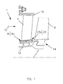
- the compressor has, alternately in an axial direction parallel to the axis 2 of the compressor, stator vanes 4 and rotor blades 6.
- the stator vanes 4, distributed circumferentially around the axis 2, are integrated in a stator portion also object of the invention, further comprising an inner ferrule 8 of radially inner delimitation of a primary annular flow 10 through the turbine engine, the ferrule 8 carrying the feet of the blades 4 which pass through.
- stator portion also comprises additional elements reported on the shell 8, which will be described later, such as a radially inner abradable coating forming annular sealing strip, contacted by a sealing device 12 carried by the rotor stage 14 carrying the rotating vanes 6 and arranged downstream of the stator portion concerned.
- the rotating sealing device 12 is in a known manner of labyrinth or wipe type.
- the shell 8 is an integral part of an annular stator structure bearing the reference 23 on the figure 1 .
- stator of the compressor also comprises an outer shell 16 of outer radial delimitation of the primary annular flow 10 passing through the turbine engine, this ferrule 16 carrying the heads of the vanes 4 of the aforementioned stator portion.
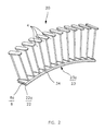
- This stator part is preferably composed by the setting up of a plurality of assemblies 20 such as that shown on FIG. figure 2 , each constituting an angular or circumferential portion of this stator portion.
- each assembly 20 comprises an angular sector of ferrule 8a carrying a plurality of stator vanes 4, the ferrule 8 resulting from the establishment of all sectors 8a on the stator thus adopting a so-called segmented design, as opposed to a design also envisaged, called continuous, wherein the ferrule is unique and continuous 360 °.
- the angular sectors 8a (only one visible on the figure 2 ) together forming the shell 8 are preferably free of direct rigid mechanical connections connecting them to each other, their adjacent ends being in fact simply placed opposite each other, with or without play.
- the segmentation operated for the ferrule 8 is also adopted, in an identical manner, for the radially inner abradable coating forming annular sealing track 22, only an angular sector 22a of this annular coating 22 being fixedly supported by the ferrule sector 8a. . They together form part of an angular sector of the annular structure object of the invention, which also adopts a so-called segmented configuration.
- the number of assemblies 20 to form the aforementioned annular stator portion may be between 6 and 14, each set 20 preferably having the same angular / circumferential extent.
- the assembly 20 comprises, in addition to the blades 4 which have been voluntarily removed, the ferrule sector 8a, the abradable coating sector 22a, and, interposed between these two sectors, filling means 24 which will be detailed below.
- the sectors 8a, 22a and the means 24 thus jointly form an annular structure sector 23 of the assembly 20, this sector bearing the reference numeral 23a.
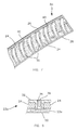
- the sector 8a has an inverted U-shaped overall section whose two branches 26 of the U extend substantially in an inner radial direction 28, starting from the base 32 of this U.
- the outer surface 34 of this U, oriented according to an outer radial direction 30 is that ensuring the internal delimitation of the primary flow of the turbine engine.
- the sector 8a comprises a plurality of circumferentially spaced holes 36, each intended to receive the foot of a stator vane, and being partly made through the base of the U 32.
- each aperture 36 is filled with a vibration damping material 38 surrounding the foot of the associated blade.
- This vibration-damping material 38 is preferably designed to fit the entire delimiting surface of the aperture 36, and forms consequently a continuous band and closed around the foot of dawn which it surrounds.
- a housing slot 39 whose geometry corresponds to the counter-shape of the blade root that it receives, and on the other hand an outer surface corresponding to the counter-shape of the inner wall a journey 36, which also has a substantially identical shape or similar to that of the blade root, but enlarged.
- This vibration absorbing material 38 of the stator vanes is for example made of silicone resin, preferably so-called structural silicone, that is to say having a low hardness, for example between 25 and 45 shore A.
- the openings are not only practiced in the thickness of the base of U 32, but extended radially inwards by means of stiffening of the sector here taking the form of a rib 40 projecting from this base 32
- Each rib 40 extends in a closed manner around the periphery of the aperture 36 which it defines, together with the opening made in the base 32 which it extends, so that it adopts a substantially identical geometry or similar to that of the foot, but enlarged.
- the rib 40 may be attached to the branches of the U 26 by melting in them, respectively at the portions of the a journey facing the leading edge and the trailing edge of the blade root.
- the ratio between the thickness of the base of the U 32 traversed by the aperture and the radial distance projecting from the rib 40 completing the same aperture is preferably between 1 and 1/3.
- the closed rib 40 which could alternatively take the form of two half-ribs placed respectively on either side of the aperture 36, each extending from one to the other of the two branches of the U 26, without being connected to each other at their ends, reinforces the rigidity of the sector 8a.
- a circumferential rib 42 also projecting radially inwardly from the base 32, being interrupted by the openings 36 at the ribs 40.
- a space 44 open in the inner radial direction is formed between two openings 36 directly consecutive. This space 44 is delimited in the outer radial direction by the base 32 of the U, and in both directions of the circumferential direction 46 by the two ribs 40 of the two openings concerned, respectively.
- the ferrule sector 8a comprising the elements 26, 32, 40 and 42, is preferably made in one piece by high-pressure injection molding of thermoplastic composite material, comprising for example a mixture of polyetherimide resin and carbon fibers. and / or glass fibers.
- the filling means 24 taking for example the form of foam blocks, preferably non-metallic and closed cell, such that the rigid polymethacrylimide foam, for example that sold under the trademark ROHACELL ® from Degussa-Rohacell society.
- foam blocks preferably non-metallic and closed cell
- the rigid polymethacrylimide foam for example that sold under the trademark ROHACELL ® from Degussa-Rohacell society.
- Other low density polymer foams can be used, such as polyurethane foam or polyetherimide.
- the filling means 24 are made of a light material whose density is lower than that of the material constituting the subsequently deposited inner abradable coating, the ratio between the densities being preferably less than 0.1.
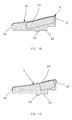
- each space 44 is partially filled with the same block of foam 24 of section substantially identical to that of the space 44 that it occupies, in order to marry simultaneously the base 32 and the branches 26 of the U, as well as the two ribs 40 delimiting this space, as shown on the figure 7 .
- each block 24 may have a groove on its radially upper face for the passage of the circumferential rib 42.
- the foam block forming a light filling material does not extend throughout its associated space 44 in the inner radial direction, even if it could to be the case. In this respect, it could even extend beyond this space, without departing from the scope of the invention.
- the inner wall of the openings 36 is equipped with the contour of vibration damping material 38, which extends over the entire length of the openwork concerned by revealing the slot of dawn housing 39, through or not, as shown in FIG. figure 8 .
- the contour 38 extends to the inner radial end of the aperture 36, without projecting therefrom.
- the material used is preferably of the low-hardness silicone resin type, so as to have good damping characteristics.
- the vibration damping structural silicone resin is preferentially in the form of a slightly viscous liquid.
- these preforms can then be placed in their respective openings 36 before making the coating sector 22a.
- the process is continued by producing the coating sector 22a, the latter having an external radial portion penetrating the portions of the spaces. 44 not filled by the foam blocks 24 already installed, this outer radial portion being interrupted in the circumferential direction by the openings 36. Furthermore, its inner radial portion is continuous along the sector 8a, and forms the sealing track 50 intended to be contacted by the above labyrinth seal, as visible on the figure 9 . Moreover, as shown on the figure 3 , the abradable coating sector 22a extends radially inwards beyond the branches of the U 26.
- the sector 22a is made of silicone elastomer with a density greater than that of the foam of the filling blocks 24, for example of the RTV silicone type.
- stator vane feet are inserted into the housing slots 39 provided for this purpose, and the resulting assembly 20 mounted on the stator of the compressor by fixing these same vanes on the outer shell 16.
- Each aperture 36 may, in addition to housing the vibration damping material 38, be equipped with mechanical means of retention of the stator blade associated with this aperture.
- these means take the form of a clip 52 having a support 54 bearing on the inner radial end of the rib 40, partially delimiting the openwork concerned.
- This support 54 located outside the aperture 36, carries radially outwardly two elastic retention arms 56 penetrating into the aperture, and defining a retention slot 58 foot of the blade 4.
- the foot inserted into the slot 58 is held by the clamping exerted by the two arms 56, being noted here that the space of the opening 36 not occupied by the clip 52 can be filled by the vibration damping material described above.
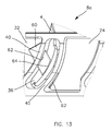
- the mechanical retention means take, for each a journey, the shape of a retention plate 60 passing through two opposite orifices 62 of the rib 40, and an orifice 64 provided in the foot of the stator vane, and aligned with the two orifices 62 between which it is located.
- the wafer 60 of shape for example substantially parallelepipedic, is found therefore located radially inwardly of the base of the U 32, preferably without contact therewith, while being substantially parallel thereto.
- the wafer 60 is shown in a configuration being mounted, since it has not yet been slid into the second orifice 62 of the rib 40.
- the annular structure 23 differs from the previous one in the first place in that the ferrule 8 no longer has openings 34 radially extended, but extending only in the thickness of the base of the U 32, 4.
- the filling means 24 here take the form of a band extending continuously over the entire annular structure 23, this band 24 being of this preferred embodiment offset axially blade roots, and preferably of constant thickness. Nevertheless, the band 24, conforming to the inner surface of the U 32 base, could be continuous while covering a portion of the blade roots, without departing from the scope of the invention.
- This preferred embodiment is preferably implemented so as to be unsegmented, with a preferably metallic ferrule. Nevertheless, it could be segmented, without departing from the scope of the invention.
- the coating 22 forming sealing strip 50 covers both the filling strip 24, and the portion of the inner surface of the U 32 base traversed by the blade roots.
- the axial length of the coating 22 is substantially identical to the axial length of this base of the U 32.
- FIGS 17 to 19 show again another embodiment for the assembly 20.
- the openings 36 extend only in the base of the U 32, and the blade roots protruding radially inwardly from this base are associated mechanical retention means in the form of retention plates 60 substantially identical or similar to those described with reference to the figure 13 .
- the difference here lies in the fact that the retention plates 60 no longer pass through the openings, each being in fact provided to cross only two successive blades feet circumferentially, through orifices 64.
- Each plate 60 is therefore located below the inner surface of the U 32 base which operates its retention, and, indirectly, the retention of two blades 4 traversed by the wafer.
- the filling means 24 generally take the form of blocks arranged between the blade roots, and matching the inner surface of the base of the U 32. These blocks 24, which are therefore circumferentially spaced apart from each other, others, may have different axial length depending on their location. Thus, as it is visible on the Figures 17 to 19 each filling block 24 located between two retention plates 60 may have a substantially long axial length due to the empty space created between these two plates, while each filling block 24 located at a retention plate 60 has an axial length substantially lower, because of the footprint created by this plate.
- these plates 60 as well as the inner surface of the base of the U 32 not covered by the blocks 24 are then covered by the coating 22 forming the sealing strip 50.
Landscapes
- Engineering & Computer Science (AREA)
- Mechanical Engineering (AREA)
- General Engineering & Computer Science (AREA)
- Structures Of Non-Positive Displacement Pumps (AREA)
- Turbine Rotor Nozzle Sealing (AREA)
Priority Applications (2)
| Application Number | Priority Date | Filing Date | Title |
|---|---|---|---|
| EP07124098.0A EP2075415B1 (de) | 2007-12-27 | 2007-12-27 | Ringstruktur des Stators in leichterer Ausführung für das Triebwerk eines Luftfahrzeugs |
| PCT/EP2008/068286 WO2009083568A1 (fr) | 2007-12-27 | 2008-12-24 | Structure annulaire de stator allegee pour turbomoteur d'aeronef |
Applications Claiming Priority (1)
| Application Number | Priority Date | Filing Date | Title |
|---|---|---|---|
| EP07124098.0A EP2075415B1 (de) | 2007-12-27 | 2007-12-27 | Ringstruktur des Stators in leichterer Ausführung für das Triebwerk eines Luftfahrzeugs |
Publications (2)
| Publication Number | Publication Date |
|---|---|
| EP2075415A1 true EP2075415A1 (de) | 2009-07-01 |
| EP2075415B1 EP2075415B1 (de) | 2016-10-19 |
Family
ID=39717623
Family Applications (1)
| Application Number | Title | Priority Date | Filing Date |
|---|---|---|---|
| EP07124098.0A Active EP2075415B1 (de) | 2007-12-27 | 2007-12-27 | Ringstruktur des Stators in leichterer Ausführung für das Triebwerk eines Luftfahrzeugs |
Country Status (2)
| Country | Link |
|---|---|
| EP (1) | EP2075415B1 (de) |
| WO (1) | WO2009083568A1 (de) |
Cited By (8)
| Publication number | Priority date | Publication date | Assignee | Title |
|---|---|---|---|---|
| FR2950116A1 (fr) * | 2009-09-15 | 2011-03-18 | Snecma | Redresseur de compresseur pour turbomachine, comprenant des tetes d'aubes montees a l'aide d'un materiau amortisseur de vibrations sur la virole exterieure |
| EP2336572A1 (de) * | 2009-12-14 | 2011-06-22 | Techspace Aero S.A. | Élément de construction et son procédé de fabrication |
| US20110243742A1 (en) * | 2010-03-30 | 2011-10-06 | Snecma | Stator stage for turbomachine compressor |
| FR2989130A1 (fr) * | 2012-04-05 | 2013-10-11 | Snecma | Etage redresseur de compresseur pour une turbomachine |
| EP2735707A1 (de) * | 2012-11-27 | 2014-05-28 | Techspace Aero S.A. | Leitrad einer axialen Turbomaschine mit segmentiertem Innendeckband und zugehöriger Verdichter |
| US20150308277A1 (en) * | 2014-04-24 | 2015-10-29 | Techspace Aero S.A. | Blade Retaining Ring for an Internal Shroud of an Axial-Flow Turbomachine Compressor |
| CN105377524A (zh) * | 2013-07-18 | 2016-03-02 | 斯奈克玛 | 用于对涡轮机部件进行组装的方法和在这种方法期间所使用的组件 |
| EP3517733A1 (de) * | 2018-01-26 | 2019-07-31 | United Technologies Corporation | Gasturbinentriebwerk mit einem ringförmigen halteband und zugehöriges montageverfahren |
Citations (9)
| Publication number | Priority date | Publication date | Assignee | Title |
|---|---|---|---|---|
| FR2330276A5 (fr) * | 1973-12-05 | 1977-05-27 | United Aircraft Corp | Amortisseur pour aubes de turbine |
| FR2404102A1 (fr) | 1977-09-27 | 1979-04-20 | Snecma | Couronne d'aubage fixe pour turbomachine axiale et son procede de realisation |
| FR2456836A1 (fr) * | 1979-05-18 | 1980-12-12 | Avco Corp | Tuyere composite en metal et ceramique, pour turbine |
| EP0433111A1 (de) * | 1989-11-15 | 1991-06-19 | Societe Nationale D'etude Et De Construction De Moteurs D'aviation "Snecma" | Statorelement einer Turbomaschine |
| US5062767A (en) * | 1990-04-27 | 1991-11-05 | The United States Of America As Represented By The Secretary Of The Air Force | Segmented composite inner shrouds |
| GB2272027A (en) * | 1992-10-28 | 1994-05-04 | Snecma | Interlocking the ends of blades |
| EP1219785A1 (de) * | 2000-12-19 | 2002-07-03 | United Technologies Corporation | Befestigungsanordnung für Turbinenleitschaufeln |
| US20030185673A1 (en) * | 2002-01-21 | 2003-10-02 | Honda Giken Kogyo Kabushiki Kaisha | Flow-rectifying member and its unit and method for producing flow-rectifying member |
| GB2418709A (en) * | 2004-09-29 | 2006-04-05 | Rolls Royce Plc | Damped assembly |
Family Cites Families (6)
| Publication number | Priority date | Publication date | Assignee | Title |
|---|---|---|---|---|
| US3879831A (en) * | 1971-11-15 | 1975-04-29 | United Aircraft Corp | Nickle base high temperature abradable material |
| US4546047A (en) * | 1981-01-14 | 1985-10-08 | United Technologies Corporation | Composite tape preform for abradable seals |
| GB2110768A (en) * | 1981-12-01 | 1983-06-22 | Rolls Royce | Fixings for stator vanes |
| US4655682A (en) * | 1985-09-30 | 1987-04-07 | United Technologies Corporation | Compressor stator assembly having a composite inner diameter shroud |
| JPH1054204A (ja) * | 1996-05-20 | 1998-02-24 | General Electric Co <Ge> | ガスタービン用の多構成部翼 |
| US6409472B1 (en) * | 1999-08-09 | 2002-06-25 | United Technologies Corporation | Stator assembly for a rotary machine and clip member for a stator assembly |
-
2007
- 2007-12-27 EP EP07124098.0A patent/EP2075415B1/de active Active
-
2008
- 2008-12-24 WO PCT/EP2008/068286 patent/WO2009083568A1/fr not_active Ceased
Patent Citations (9)
| Publication number | Priority date | Publication date | Assignee | Title |
|---|---|---|---|---|
| FR2330276A5 (fr) * | 1973-12-05 | 1977-05-27 | United Aircraft Corp | Amortisseur pour aubes de turbine |
| FR2404102A1 (fr) | 1977-09-27 | 1979-04-20 | Snecma | Couronne d'aubage fixe pour turbomachine axiale et son procede de realisation |
| FR2456836A1 (fr) * | 1979-05-18 | 1980-12-12 | Avco Corp | Tuyere composite en metal et ceramique, pour turbine |
| EP0433111A1 (de) * | 1989-11-15 | 1991-06-19 | Societe Nationale D'etude Et De Construction De Moteurs D'aviation "Snecma" | Statorelement einer Turbomaschine |
| US5062767A (en) * | 1990-04-27 | 1991-11-05 | The United States Of America As Represented By The Secretary Of The Air Force | Segmented composite inner shrouds |
| GB2272027A (en) * | 1992-10-28 | 1994-05-04 | Snecma | Interlocking the ends of blades |
| EP1219785A1 (de) * | 2000-12-19 | 2002-07-03 | United Technologies Corporation | Befestigungsanordnung für Turbinenleitschaufeln |
| US20030185673A1 (en) * | 2002-01-21 | 2003-10-02 | Honda Giken Kogyo Kabushiki Kaisha | Flow-rectifying member and its unit and method for producing flow-rectifying member |
| GB2418709A (en) * | 2004-09-29 | 2006-04-05 | Rolls Royce Plc | Damped assembly |
Cited By (15)
| Publication number | Priority date | Publication date | Assignee | Title |
|---|---|---|---|---|
| FR2950116A1 (fr) * | 2009-09-15 | 2011-03-18 | Snecma | Redresseur de compresseur pour turbomachine, comprenant des tetes d'aubes montees a l'aide d'un materiau amortisseur de vibrations sur la virole exterieure |
| EP2336572A1 (de) * | 2009-12-14 | 2011-06-22 | Techspace Aero S.A. | Élément de construction et son procédé de fabrication |
| US8794908B2 (en) * | 2010-03-30 | 2014-08-05 | Snecma | Stator stage for turbomachine compressor |
| FR2958323A1 (fr) * | 2010-03-30 | 2011-10-07 | Snecma | Etage redresseur de compresseur pour une turbomachine. |
| US20110243742A1 (en) * | 2010-03-30 | 2011-10-06 | Snecma | Stator stage for turbomachine compressor |
| FR2989130A1 (fr) * | 2012-04-05 | 2013-10-11 | Snecma | Etage redresseur de compresseur pour une turbomachine |
| US9879562B2 (en) | 2012-04-05 | 2018-01-30 | Snecma | Compressor guide-vane stage for a turbine engine including a gasket between a vane and a shroud of the guide-vane stage |
| GB2502868B (en) * | 2012-04-05 | 2018-06-27 | Snecma | A compressor guide-vane stage for a turbine engine |
| EP2735707A1 (de) * | 2012-11-27 | 2014-05-28 | Techspace Aero S.A. | Leitrad einer axialen Turbomaschine mit segmentiertem Innendeckband und zugehöriger Verdichter |
| CN105377524A (zh) * | 2013-07-18 | 2016-03-02 | 斯奈克玛 | 用于对涡轮机部件进行组装的方法和在这种方法期间所使用的组件 |
| CN105377524B (zh) * | 2013-07-18 | 2020-06-30 | 斯奈克玛 | 用于对涡轮机部件进行组装的方法和在这种方法期间所使用的组件 |
| US20150308277A1 (en) * | 2014-04-24 | 2015-10-29 | Techspace Aero S.A. | Blade Retaining Ring for an Internal Shroud of an Axial-Flow Turbomachine Compressor |
| US9995159B2 (en) * | 2014-04-24 | 2018-06-12 | Safran Aero Boosters Sa | Blade retaining ring for an internal shroud of an axial-flow turbomachine compressor |
| EP3517733A1 (de) * | 2018-01-26 | 2019-07-31 | United Technologies Corporation | Gasturbinentriebwerk mit einem ringförmigen halteband und zugehöriges montageverfahren |
| US10669894B2 (en) | 2018-01-26 | 2020-06-02 | Raytheon Technologies Corporation | Annular retention strap |
Also Published As
| Publication number | Publication date |
|---|---|
| EP2075415B1 (de) | 2016-10-19 |
| WO2009083568A1 (fr) | 2009-07-09 |
Similar Documents
| Publication | Publication Date | Title |
|---|---|---|
| EP2075415B1 (de) | Ringstruktur des Stators in leichterer Ausführung für das Triebwerk eines Luftfahrzeugs | |
| EP2366060B1 (de) | Gebläse für ein Turbotriebwerk mit einem Auswuchtsystem mit Blindlöchern zur Unterbringung von Gewichten und zugehöriges Turbotriebwerk | |
| EP1693551B1 (de) | Vorrichtung zur Positionierung einer Rotorschaufel und beschaufelte Rotorscheibe mit einer solchen Vorrichtung | |
| EP2196629B1 (de) | Segmentierter Verbundmantelring eines axialen Verdichters | |
| EP2459884B1 (de) | Aussenhüllenabschnitt für einen beschaufelten statorring eines flugzeugtriebwerks mit schwingungsdämpfenden blöcken | |
| CA2802821C (fr) | Secteur angulaire de redresseur pour compresseur de turbomachine | |
| EP3049637B1 (de) | Rotierende anordnung fuer turbomaschine | |
| EP3161263B1 (de) | Rotational system of a turbomachine | |
| EP2075414A1 (de) | Stator-Innenring für die Begrenzung des Primärflusses des Triebwerks eines Luftfahrzeugs | |
| CA2912233C (fr) | Aube creuse et procede de fabrication associe | |
| FR2955608A1 (fr) | Amortisseur de vibrations a lamelle et chemises entre talons d'aubes adjacentes en materiau composite d'une roue mobile de turbomachine. | |
| FR2930592A1 (fr) | Distributeur de turbine pour une turbomachine | |
| FR2968030A1 (fr) | Turbine basse-pression de turbomachine d'aeronef, comprenant un distributeur sectorise de conception amelioree | |
| CA2925438C (fr) | Ensemble rotatif pour turbomachine | |
| EP2058473B1 (de) | Durch Formguss hergestellte Metalllaufradschaufel | |
| FR2963383A1 (fr) | Aube de turbomachine, rotor, turbine basse pression et turbomachine equipes d'une telle aube | |
| EP2336572B1 (de) | Zweiteiliges Gehäuse für einen Stromdiffusor eines Axialkompressors | |
| FR3020408A1 (fr) | Ensemble rotatif pour turbomachine | |
| EP3781791A1 (de) | Turbinendüse für einen turbinenmotor mit einem passiven system zum wiedereinführen von blow-by-gas in einen gasstrahl | |
| EP2427659B1 (de) | Stator-ring für triebwerk eines luftfahrzeugs mit nuten für die mechanische entladung von schaufeln | |
| EP2948640B1 (de) | Feste diffusorschaufelanordnung zur strömungslenkung durch eine turbomaschine mit einer internen plattform mit integrierten verstärkungen und zugehörige turbomaschine sowie herstellungsverfahren | |
| EP4330023A1 (de) | Vorrichtung zum formen eines schaufelteils eines turbinenmotors | |
| WO2016139416A1 (fr) | Disque aubage monobloc comportant un moyeu ayant une face evidee a laquelle est rapporte un organe de comblement | |
| FR2950116A1 (fr) | Redresseur de compresseur pour turbomachine, comprenant des tetes d'aubes montees a l'aide d'un materiau amortisseur de vibrations sur la virole exterieure | |
| FR3107725A1 (fr) | Ensemble pour stator de turbomachine d’aéronef, à étanchéité renforcée entre une virole externe et une couronne aubagée de stator entourée par cette virole |
Legal Events
| Date | Code | Title | Description |
|---|---|---|---|
| PUAI | Public reference made under article 153(3) epc to a published international application that has entered the european phase |
Free format text: ORIGINAL CODE: 0009012 |
|
| AK | Designated contracting states |
Kind code of ref document: A1 Designated state(s): AT BE BG CH CY CZ DE DK EE ES FI FR GB GR HU IE IS IT LI LT LU LV MC MT NL PL PT RO SE SI SK TR |
|
| AX | Request for extension of the european patent |
Extension state: AL BA HR MK RS |
|
| 17P | Request for examination filed |
Effective date: 20091026 |
|
| AKX | Designation fees paid |
Designated state(s): BE DE FR GB |
|
| 17Q | First examination report despatched |
Effective date: 20150430 |
|
| GRAP | Despatch of communication of intention to grant a patent |
Free format text: ORIGINAL CODE: EPIDOSNIGR1 |
|
| INTG | Intention to grant announced |
Effective date: 20160511 |
|
| GRAS | Grant fee paid |
Free format text: ORIGINAL CODE: EPIDOSNIGR3 |
|
| GRAA | (expected) grant |
Free format text: ORIGINAL CODE: 0009210 |
|
| AK | Designated contracting states |
Kind code of ref document: B1 Designated state(s): BE DE FR GB |
|
| REG | Reference to a national code |
Ref country code: GB Ref legal event code: FG4D Free format text: NOT ENGLISH |
|
| REG | Reference to a national code |
Ref country code: DE Ref legal event code: R096 Ref document number: 602007048357 Country of ref document: DE |
|
| REG | Reference to a national code |
Ref country code: FR Ref legal event code: PLFP Year of fee payment: 10 |
|
| REG | Reference to a national code |
Ref country code: DE Ref legal event code: R097 Ref document number: 602007048357 Country of ref document: DE |
|
| PLBE | No opposition filed within time limit |
Free format text: ORIGINAL CODE: 0009261 |
|
| STAA | Information on the status of an ep patent application or granted ep patent |
Free format text: STATUS: NO OPPOSITION FILED WITHIN TIME LIMIT |
|
| 26N | No opposition filed |
Effective date: 20170720 |
|
| REG | Reference to a national code |
Ref country code: FR Ref legal event code: PLFP Year of fee payment: 11 |
|
| PGFP | Annual fee paid to national office [announced via postgrant information from national office to epo] |
Ref country code: DE Payment date: 20191119 Year of fee payment: 13 |
|
| PGFP | Annual fee paid to national office [announced via postgrant information from national office to epo] |
Ref country code: GB Payment date: 20191122 Year of fee payment: 13 |
|
| REG | Reference to a national code |
Ref country code: DE Ref legal event code: R119 Ref document number: 602007048357 Country of ref document: DE |
|
| GBPC | Gb: european patent ceased through non-payment of renewal fee |
Effective date: 20201227 |
|
| PG25 | Lapsed in a contracting state [announced via postgrant information from national office to epo] |
Ref country code: DE Free format text: LAPSE BECAUSE OF NON-PAYMENT OF DUE FEES Effective date: 20210701 Ref country code: GB Free format text: LAPSE BECAUSE OF NON-PAYMENT OF DUE FEES Effective date: 20201227 |
|
| PGFP | Annual fee paid to national office [announced via postgrant information from national office to epo] |
Ref country code: FR Payment date: 20251222 Year of fee payment: 19 |
|
| PGFP | Annual fee paid to national office [announced via postgrant information from national office to epo] |
Ref country code: BE Payment date: 20251224 Year of fee payment: 19 |