EP2075418A2 - Ensemble de soupape de vapeur et usine de turbine de vapeur - Google Patents
Ensemble de soupape de vapeur et usine de turbine de vapeur Download PDFInfo
- Publication number
- EP2075418A2 EP2075418A2 EP20080020527 EP08020527A EP2075418A2 EP 2075418 A2 EP2075418 A2 EP 2075418A2 EP 20080020527 EP20080020527 EP 20080020527 EP 08020527 A EP08020527 A EP 08020527A EP 2075418 A2 EP2075418 A2 EP 2075418A2
- Authority
- EP
- European Patent Office
- Prior art keywords
- steam
- valve
- flow path
- casing
- main
- Prior art date
- Legal status (The legal status is an assumption and is not a legal conclusion. Google has not performed a legal analysis and makes no representation as to the accuracy of the status listed.)
- Granted
Links
Images


Classifications
-
- F—MECHANICAL ENGINEERING; LIGHTING; HEATING; WEAPONS; BLASTING
- F01—MACHINES OR ENGINES IN GENERAL; ENGINE PLANTS IN GENERAL; STEAM ENGINES
- F01D—NON-POSITIVE DISPLACEMENT MACHINES OR ENGINES, e.g. STEAM TURBINES
- F01D17/00—Regulating or controlling by varying flow
- F01D17/10—Final actuators
-
- F—MECHANICAL ENGINEERING; LIGHTING; HEATING; WEAPONS; BLASTING
- F01—MACHINES OR ENGINES IN GENERAL; ENGINE PLANTS IN GENERAL; STEAM ENGINES
- F01D—NON-POSITIVE DISPLACEMENT MACHINES OR ENGINES, e.g. STEAM TURBINES
- F01D1/00—Non-positive-displacement machines or engines, e.g. steam turbines
-
- F—MECHANICAL ENGINEERING; LIGHTING; HEATING; WEAPONS; BLASTING
- F01—MACHINES OR ENGINES IN GENERAL; ENGINE PLANTS IN GENERAL; STEAM ENGINES
- F01D—NON-POSITIVE DISPLACEMENT MACHINES OR ENGINES, e.g. STEAM TURBINES
- F01D17/00—Regulating or controlling by varying flow
- F01D17/10—Final actuators
- F01D17/12—Final actuators arranged in stator parts
- F01D17/14—Final actuators arranged in stator parts varying effective cross-sectional area of nozzles or guide conduits
- F01D17/141—Final actuators arranged in stator parts varying effective cross-sectional area of nozzles or guide conduits by means of shiftable members or valves obturating part of the flow path
- F01D17/145—Final actuators arranged in stator parts varying effective cross-sectional area of nozzles or guide conduits by means of shiftable members or valves obturating part of the flow path by means of valves, e.g. for steam turbines
-
- F—MECHANICAL ENGINEERING; LIGHTING; HEATING; WEAPONS; BLASTING
- F01—MACHINES OR ENGINES IN GENERAL; ENGINE PLANTS IN GENERAL; STEAM ENGINES
- F01K—STEAM ENGINE PLANTS; STEAM ACCUMULATORS; ENGINE PLANTS NOT OTHERWISE PROVIDED FOR; ENGINES USING SPECIAL WORKING FLUIDS OR CYCLES
- F01K11/00—Plants characterised by the engines being structurally combined with boilers or condensers
-
- F—MECHANICAL ENGINEERING; LIGHTING; HEATING; WEAPONS; BLASTING
- F05—INDEXING SCHEMES RELATING TO ENGINES OR PUMPS IN VARIOUS SUBCLASSES OF CLASSES F01-F04
- F05D—INDEXING SCHEME FOR ASPECTS RELATING TO NON-POSITIVE-DISPLACEMENT MACHINES OR ENGINES, GAS-TURBINES OR JET-PROPULSION PLANTS
- F05D2220/00—Application
- F05D2220/30—Application in turbines
- F05D2220/31—Application in turbines in steam turbines
-
- F—MECHANICAL ENGINEERING; LIGHTING; HEATING; WEAPONS; BLASTING
- F05—INDEXING SCHEMES RELATING TO ENGINES OR PUMPS IN VARIOUS SUBCLASSES OF CLASSES F01-F04
- F05D—INDEXING SCHEME FOR ASPECTS RELATING TO NON-POSITIVE-DISPLACEMENT MACHINES OR ENGINES, GAS-TURBINES OR JET-PROPULSION PLANTS
- F05D2220/00—Application
- F05D2220/70—Application in combination with
- F05D2220/72—Application in combination with a steam turbine
-
- F—MECHANICAL ENGINEERING; LIGHTING; HEATING; WEAPONS; BLASTING
- F05—INDEXING SCHEMES RELATING TO ENGINES OR PUMPS IN VARIOUS SUBCLASSES OF CLASSES F01-F04
- F05D—INDEXING SCHEME FOR ASPECTS RELATING TO NON-POSITIVE-DISPLACEMENT MACHINES OR ENGINES, GAS-TURBINES OR JET-PROPULSION PLANTS
- F05D2250/00—Geometry
- F05D2250/30—Arrangement of components
- F05D2250/31—Arrangement of components according to the direction of their main axis or their axis of rotation
- F05D2250/312—Arrangement of components according to the direction of their main axis or their axis of rotation the axes being parallel to each other
-
- Y—GENERAL TAGGING OF NEW TECHNOLOGICAL DEVELOPMENTS; GENERAL TAGGING OF CROSS-SECTIONAL TECHNOLOGIES SPANNING OVER SEVERAL SECTIONS OF THE IPC; TECHNICAL SUBJECTS COVERED BY FORMER USPC CROSS-REFERENCE ART COLLECTIONS [XRACs] AND DIGESTS
- Y10—TECHNICAL SUBJECTS COVERED BY FORMER USPC
- Y10T—TECHNICAL SUBJECTS COVERED BY FORMER US CLASSIFICATION
- Y10T137/00—Fluid handling
- Y10T137/8593—Systems
- Y10T137/87096—Valves with separate, correlated, actuators
- Y10T137/87121—Coaxial stems
-
- Y—GENERAL TAGGING OF NEW TECHNOLOGICAL DEVELOPMENTS; GENERAL TAGGING OF CROSS-SECTIONAL TECHNOLOGIES SPANNING OVER SEVERAL SECTIONS OF THE IPC; TECHNICAL SUBJECTS COVERED BY FORMER USPC CROSS-REFERENCE ART COLLECTIONS [XRACs] AND DIGESTS
- Y10—TECHNICAL SUBJECTS COVERED BY FORMER USPC
- Y10T—TECHNICAL SUBJECTS COVERED BY FORMER US CLASSIFICATION
- Y10T137/00—Fluid handling
- Y10T137/8593—Systems
- Y10T137/87917—Flow path with serial valves and/or closures
Definitions
- the present invention relates to a steam valve assembly having a main steam-stop valve and a steam control valve, and to a steam turbine plant that has the steam valve assembly.
- the steam valve assembly has a main-steam stop va!ve and a steam control valve that is arranged downstream of the main-steam stop valve.
- the main-steam stop valve can instantaneously stop steam flowing into the steam turbine if abnormality develops in the steam turbine.
- the steam control valve is configured to control the flow rate at which stream is supplied to the steam turbine.
- a main-steam stop valve of horizontal type (laid horizontal) and a steam control valve if vertical (standing vertical) type may be combined as disclosed in Japanese Patent Application Laid-Open Publication No. 2006-183582 , FIG. 8.
- the valve body of the main-steam stop valve is driven by a hydraulic cylinder arranged beside a side cover, via a valve stem that penetrates the side cover and extends horizontally.
- the valve body of the stream control valve is driven by another hydraulic cylinder arranged above the top cover (or below the bottom cover), via another valve stem that penetrates the top (or bottom) cover and extends vertically.
- both the main-steam stop valve and the steam control valve are vertical (standing vertical types) as disclosed in Japanese Patent Application Laid-Open Publication No. 2006-183582 , FIG. 8 and FIG. 12; Japanese Patent Application Laid-Open Publication No. 10-176502 , FIG. 1 ; and Japanese Utility Model Application Laid-Open Publication No. 63-82002 .
- the valve body of either the main-steam stop valve or the steam control valve is driven by a hydraulic cylinder arranged above the casing, via a valve stem that extends vertically and penetrates the casing.
- the valve body of the other valve is driven by another hydraulic cylinder arranged below the casing, via another valve stem that extends vertically and penetrates the casing.
- a steam valve apparatus that is a combination of the two conventional vertical type valves, however, any one of the valve stems that slide up and down through the casings of the main-steam stop valve and steam control valve extend toward downstream side of the valve seat.
- most valve apparatuses should have no components that may cause a pressure loss downstream of any valve seat.
- a steam valve assembly which is a combination of the two conventional vertical (standing vertical) type valves, the valve stem of the two steam-stop valve or steam control valve makes an obstacle to the flowing steam when the valve is opened. This inevitably results in a large pressure loss.
- An object of the invention is to provide a steam valve assembly which can be maintained at high efficiency and in which the pressure loss when the valve is in an open position can be reduced.
- a steam valve assembly (21) having a main-steam stop valve (1), a steam control valve (2) arranged downstream of the main-steam stop valve (1), and an intermediate flow path (30) provided between, and connecting, the main-steam stop valve (1) and the steam control valve (2), characterized in that: the main-steam stop valve (1) comprises: a first casing (31) having a first inlet port (33) directing horizontally, and a first outlet port (34) directing vertically and connected to the intermediate flow path (30), defining a first flow path between the first inlet port (33) and the first outlet port (34), and having a first valve seat (35) arranged in the first flow path; a first valve body (32) configured to move up and down in the first casing (31) and to contact and leave the first valve seat (35), thereby to close and open the first flow path; and a first valve stem (37) connected to the first valve body (32), configured to slide up and down, penetrating the first casing (31), and configured to move away from
- a steam turbine plant having a boiler (20), a steam turbine (10) configured to receive main steam generated in the boiler (20) and to be driven with the main steam, and a steam valve assembly (21) arranged between the boiler (20) and the steam turbine (10) and configured to control a flow of the main steam
- the steam valve assembly (21) has a main-steam stop valve (1), a steam control valve (2) arranged downstream of the main-steam stop valve (1), and an intermediate flow path(30) provided between, and connecting, the main-steam stop valve (1) and the steam control valve (2), characterized in that: the main-steam stop valve (1) comprises: a first casing (31) having a first inlet port (33) directing horizontally, and a first outlet port (34) directing vertically and connected to the intermediate flow path (30), defining a first flow path between the first inlet port (33) and the first outlet port (34), and having a first valve seat (35) arranged in the first flow path; a first valve body (32) configured to move up
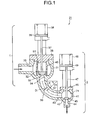
- FIG. 1 is a vertical sectional view showing a first embodiment of a steam valve assembly according to the present invention.
- FIG. 2 is a system diagram showing a steam turbine plant that has the steam valve assembly according to the present invention.
- the steam turbine plant is so designed that, as shown in FIG. 2 , the steam flowing from a boiler 20 is supplied to a high-pressure steam turbine 10 via the steam valve assembly 21.
- the steam valve assembly 21 has a main-steam stop valve 1 and a steam control valve 2 arranged downstream of the main-steam stop valve 1.
- the steam that has done work in a high-pressure steam turbine 10 flows through a check valve 7 back into the boiler 20.
- the steam is heated again by a re-heater.
- the re-heated steam flows through a re-heated steam stop valve 3 and an intercept valve 4 into an intermediate-pressure steam turbine 11 , and then to a low-pressure steam turbine 12.
- the steam performs work in both the intermediate-pressure steam turbine 11 and the low-pressure steam turbine 12.
- the steam coming from the low-pressure steam turbine 12 flows into a condenser 13.
- the condenser 13 changes the steam into water.
- the condensed water is pumped up into the boiler 20 by a feed water pump 14.
- a high-pressure turbine bypass valve 5 extends from the upstream side of the main-steam stop valve 1 to the upstream side of the re-heater of the boiler 20, and a low-pressure turbine bypass valve 6 extends from the downstream side of the re-heater of the boiler 20 to the condenser 13.
- These bypass valves 5 and 6 are provided to increase the operating efficiency of the steam turbine plant. They enable the boiler system to operate by itself, circulating steam, whether the turbines are operating or not.
- the steam valve assembly 21 has a main-steam stop valve 1, a steam control valve 2, and an intermediate flow path 30 connecting the valves 1 and 2.
- the main-steam stop valve 1 is provided at the upstream side of the steam control valve 2.
- Both the main-steam stop valve 1 and the steam control valve 2 are of the vertical (standing vertical) type. Note that FIG. 1 shows the main-steam stop valve 1 and the steam control valve 2, both in closed state.
- the main-steam stop valve 1 has a first casing 31 and a first valve body 32.
- the first casing 31 defines a first flow path 61.
- the first valve body 32 can move up and down in the first casing 31.
- the first casing 31 has a first inlet port 33 and a first outlet port 34.
- the first inlet port 33 directs horizontally and guides steam into the first casing 31.
- the first outlet port 34 directs vertically and guides steam downward from the first casing 31.
- a first valve seat 35 is arranged in the first outlet port 34, bulging inwards. As the first valve body 32 moves up, the first valve body 32 leaves the first valve seat 35, opening the first flow path 61. Conversely, as the first valve body 32 moves down, the first valve body 32 contacts the first valve seat 35, closing the first flow path 61.
- a first valve cover 36 is arranged on the top of the first casing 31.
- the first valve cover 36 can be opened to facilitate the maintenance work.
- a first valve stem 37 is fixed to the first valve body 32.
- the first valve stem 37 extends upward from the first valve body 32, penetrates the first valve cover 36 of the first casing 31 and is connected to a first piston 39 provided in a first hydraulic cylinder 38.
- the first valve stem 37 is located, opposing the first outlet port 34 across the first valve body 32.
- the first valve stem 37 can be moved upward away from the first outlet port 34 in order to move the first valve body 32 away from the first valve seat 35 (thereby to open the first flow path 61).
- a strainer 40 is arranged, surrounding the first valve body 32.
- the steam control valve 2 is almost identical in structure to the main-steam stop valve 1.
- the steam control valve 2 has a second casing 41 and a second valve body 42.
- the second casing 41 defines a second flow path 71.
- the second valve body 42 can move up and down in the second casing 41.
- the second casing 41 has a second inlet port 43 and a second outlet port 44.
- the second inlet port 43 directs horizontally and guides steam into the second casing 41.
- the second outlet port 44 directs vertically and guides steam downward from the second casing 41.
- a second valve seat 45 is arranged in the second outlet port 44, bulging inwards. As the second valve body 42 moves up, the second valve body 42 leaves the second valve seat 45, opening the second flow path 71. Conversely, as the second valve body 42 moves down, the second valve body 42 contacts the second valve seat 45, closing the second flow path 71.
- a second valve cover 46 is arranged on the top of the second casing 41.
- the second valve cover 46 can be opened to facilitate the maintenance work.
- a second valve stem 47 is fixed to the second valve body 42.
- the second valve stem 47 extends upward from the second valve body 42, penetrates the second valve cover 46 and is connected to a second piston 49 provided in a second hydraulic cylinder 48.
- the second valve stem 47 is located, opposing the second outlet port 44 across the second valve body 42.
- the second valve stem 47 can be moved upward away from the second outlet port 44 in order to move the second valve body 42 away from the second valve seat 45 (thereby to open the second flow path 71).
- the intermediate flow path 30 defines one arcuate elbow that connects the first outlet port 34 and the second inlet port 43.
- the intermediate flow path 30 has a bending angle of 90°.
- the ratio (R/Di) of the radius R of curvature of the intermediate flow path 30 to the inner diameter Di of the intermediate flow path 30 should be as large as possible.
- the radio R/Di is preferably 1 or more, more preferably 2 or more.
- first casing 31 of the main-steam stop valve 1, the second casing 41 of the steam control valve 2 and the intermediate flow path 30 can be formed as a single unit, by means of forging or casting.
- the main steam supplied from the boiler 20 flows horizontally through the first inlet port 33 into the first casing 31 of the main-steam stop valve 1. Then, the steam flows into the strainer 40, passes through the gap between the first valve body 32 and the first valve seat 35, flows downward through the outlet port 34, and passes through the main-steam stop valve 1.
- the main steam flows through the intermediate flow path 30. While flowing through the intermediate flow path 30, the main steam changes its direction, from a downward direction to a horizontal direction. Thus, it horizontally flows through the second inlet port 43 into the second casing 41 of the steam control valve 2. In the second casing 41, the steam passes through the gap between the second valve body 42 and the second valve seat 45. Thus, the steam flows downward through the second outlet port 44, passing through the steam control valve 2.
- the first valve body 32 of the main-steam stop valve 1 moves up and down as the first valve stem 37 so moves.
- the first valve stem 37 is pulled in upstream direction, not disturbing the main-steam flow path at all.
- the pressure loss attributable to the first valve 37 is therefore minimized.
- the second valve body 42 of the steam control valve 2 moves up and down as the second valve stem 47 so moves. When the steam control valve 2 is fully open, the second valve stem 47 is pulled in upstream direction, not disturbing the steam flow path at all. The pressure loss attributable to the second valve 47 is therefore minimized.
- both the main-steam stop valve 1 and the steam control valve 2 can be of vertical (standing vertical) type.
- the valve stems do not bend by the weight of the valve bodies, while the valves are assembled and disassembled. Therefore, the valve bodies at the distal ends of the valve stems can easily be set into contact with the valve seats.
- the internal components such as hydraulic cylinders and top covers, can be hoisted up and down in vertical position when overhauling the valves, by using ceiling cranes. This helps to perform the maintenance work in safety.
- a centrifugal force acts on fluid that is flowing in an elbow.
- the centrifugal force exerted on that part of the fluid, which flows fast along the center part of the elbow is larger than the force exerted on that part of the fluid, which slowly flows near the wall of the elbow.
- the fluid flowing along the center part moves outward to the outer circumference of the elbow, while the fluid flowing near the wall moves inwards.
- the pressure distribution in the cross section of the elbow is not uniform, and the pressure is higher at the outer circumference of the elbow and lower at the inner circumference of the elbow. Consequently, a secondary flow is generated in the elbow.
- the secondary flow causes flow separation as a consecutive flow of the secondary flow, which will be described below.
- a greater part of the steam-pressure loss in the intermediate flow path (the elbow) 30 is attributable to the flow separation in the elbow.
- the flow separation in the intermediate flow path (the elbow) 30 can be avoided if the ratio (R/Di) of the radius R of curvature of the intermediate flow path 30 to the inner diameter Di of the intermediate flow path 30 is set to 1 or more, preferably 2 or more.
- the pressure loss in the intermediate flow path 30 can be reduced.
- FIG. 3 is a vertical sectional view showing a second embodiment of the steam valve assembly according to the present invention.
- the steam valve assembly 21 according to the second embodiment is almost identical in structure to the steam valve assembly according to the first embodiment.
- the main-steam stop valve 1, the steam control valve 2, and the intermediate flow path 30 are formed as separate units, each by means of forging or casting. Thereafter, the first casing 31 of the main-steam stop valve 1, the intermediate flow path 30, and the second casing 41 of the steam control valve 2 are connected by, for example, welding, at the junctions 55.
- Fluid is known to flow in such a complex manner as explained in conjunction with the first embodiment. Centrifugal force is applied on that part of fluid, which flows along the center part of the intermediate flow path 30. This part of the fluid is pushed outward to the outer circumference of the intermediate flow path 30. Inevitably, the inner surface of the intermediate flow path 30 is locally corroded.
- the intermediate flow path 30 is made of material different from that of the first casing 31 of the main-steam stop valve 1 and the second casing 41 of the steam control valve 2. More precisely, the intermediate flow path 30 may be made of material that contains nickel or chromium and is therefore resistant to corrosion.
- the intermediate flow path 30 made of such material, first casing 31 and second casing 41 are welded together, forming an integral unit.
- the first casing 31 of the main-steam stop valve 1 and the second casing 41 of the steam control valve 2 may be castings of chromium-molybdenum-vanadium.
- the material contains chromium and molybdenum, which enhances strength at high temperature.
- the material also contains vanadium for suppressing the surface instability of the material, which results from the use of chromium and molybdenum. Casting is the most appropriate method of manufacturing the first casing 31 and second casing 41, because these components have complicated shapes.
- the steam passing through the steam valves is to be heated to 600°C or more. If the steam is so heated, however, the conventional chromium-molybdenum-vanadium casing cannot withstand the steam in terms of strength. Forged steel components having high chromium content, which have no internal defects, should be used instead as new material.
- the first casing 31, the second casing 41 and the intermediate flow path 30 should better be separately made in the form of forged or cast components and be welded together to provide an integral unit.
- These components may be made in the form of a single cast component as has been hitherto practiced.
- a cast component has a complicated shape, being constituted of parts different in wall thickness. Consequently, when the steam turbine is activated, large thermal stresses may inevitably develop in the cast component due to a difference between the temperature at the outer surface and the temperature at the inner surface.
- the combination of the first casing 31, the second casing 41 and the intermediate flow path 30, which are forged or cast components has a uniform wall thickness and is therefore strong enough.
- FIG. 4 is a vertical sectional view showing a third embodiment of the steam valve assembly according to the present invention.
- This embodiment is a modification of the first embodiment.
- the intermediate flow path has one arcuate elbow having a bending angle of 90°.
- the intermediate flow path 30 is a combination of an arcuate elbow 50 and a straight flow-path part 51.
- the elbow 50 is connected to the outlet port (first outlet port) 34 of the main-steam stop valve 1 and has a bending angle of 45°.
- the straight flow-path part 51 is connected to the lower end of the elbow 50 and obliquely extends downward.
- the flow separation of the steam flowing in the elbow can be more suppressed, and the pressure loss can be further reduced.
- the ratio (R/Di) of the radius R of curvature of the elbow 50 to the inner diameter Di of the elbow 50 should preferably be 2 or more as in the first embodiment.
- two elbows 50, each having a bending angle of 45°, are connected by one straight flow-path part 51, and the total bending angle is therefore 90°.
- three or more elbows 50 and a plurality of straight flow-paths 51 may be combined to provide an intermediate flow path 30.
- the embodiments described above are no more than examples, and they do not limit the present invention.
- the embodiments described above may be used in any possible combinations.
- the main-steam stop valve 1, steam control valve 2 and intermediate flow path 30 may be made as a single unit by forging or casting, as in the first embodiment, or they may be prepared as separate components, each by forging or casting, and then connected together by welding, as in the second embodiment.
- each embodiment described above may be turned upside down.
Landscapes
- Engineering & Computer Science (AREA)
- Mechanical Engineering (AREA)
- General Engineering & Computer Science (AREA)
- Chemical & Material Sciences (AREA)
- Combustion & Propulsion (AREA)
- Control Of Turbines (AREA)
- Lift Valve (AREA)
Priority Applications (1)
| Application Number | Priority Date | Filing Date | Title |
|---|---|---|---|
| PL08020527T PL2075418T3 (pl) | 2007-12-25 | 2008-11-26 | Zespół zaworu parowego oraz instalacja turbiny wiatrowej |
Applications Claiming Priority (1)
| Application Number | Priority Date | Filing Date | Title |
|---|---|---|---|
| JP2007332057A JP5022887B2 (ja) | 2007-12-25 | 2007-12-25 | 蒸気弁装置および蒸気タービンプラント |
Publications (3)
| Publication Number | Publication Date |
|---|---|
| EP2075418A2 true EP2075418A2 (fr) | 2009-07-01 |
| EP2075418A3 EP2075418A3 (fr) | 2014-04-30 |
| EP2075418B1 EP2075418B1 (fr) | 2015-09-30 |
Family
ID=40260559
Family Applications (1)
| Application Number | Title | Priority Date | Filing Date |
|---|---|---|---|
| EP08020527.1A Active EP2075418B1 (fr) | 2007-12-25 | 2008-11-26 | Ensemble de soupape de vapeur et usine de turbine de vapeur |
Country Status (6)
| Country | Link |
|---|---|
| US (1) | US8042570B2 (fr) |
| EP (1) | EP2075418B1 (fr) |
| JP (1) | JP5022887B2 (fr) |
| KR (1) | KR100992894B1 (fr) |
| CN (1) | CN101469616B (fr) |
| PL (1) | PL2075418T3 (fr) |
Cited By (2)
| Publication number | Priority date | Publication date | Assignee | Title |
|---|---|---|---|---|
| EP2392781A1 (fr) * | 2010-06-02 | 2011-12-07 | Siemens Aktiengesellschaft | Soupape de réglage et d'arrêt rapide compacte pour une turbine à vapeur |
| EP2796669A1 (fr) * | 2013-04-26 | 2014-10-29 | Kabushiki Kaisha Toshiba | Appareil de soupape de vapeur |
Families Citing this family (11)
| Publication number | Priority date | Publication date | Assignee | Title |
|---|---|---|---|---|
| US8978380B2 (en) | 2010-08-10 | 2015-03-17 | Dresser-Rand Company | Adiabatic compressed air energy storage process |
| US20120073293A1 (en) * | 2010-09-23 | 2012-03-29 | General Electric Company | Steam turbine valve having integral pressure chamber |
| CN102619997B (zh) * | 2011-02-01 | 2016-05-11 | 陈光焕 | 全封闭磁力牵引蒸汽电动阀门 |
| JP5674521B2 (ja) * | 2011-03-25 | 2015-02-25 | 株式会社東芝 | 蒸気弁装置および蒸気タービンプラント |
| US9938895B2 (en) | 2012-11-20 | 2018-04-10 | Dresser-Rand Company | Dual reheat topping cycle for improved energy efficiency for compressed air energy storage plants with high air storage pressure |
| JP6092062B2 (ja) * | 2013-09-24 | 2017-03-08 | 株式会社東芝 | 蒸気弁装置及び発電設備 |
| JP2015140686A (ja) * | 2014-01-27 | 2015-08-03 | 株式会社東芝 | 蒸気タービン配管 |
| CN106089328B (zh) * | 2016-08-10 | 2017-06-30 | 西安热工研究院有限公司 | 基于dcs数据挖掘的汽轮机调门流量特性曲线辨识方法 |
| JP6933538B2 (ja) * | 2017-09-26 | 2021-09-08 | 株式会社東芝 | 蒸気弁装置およびそれを備えた蒸気タービンプラント |
| KR102453794B1 (ko) * | 2018-07-24 | 2022-10-12 | 가부시키가이샤 후지킨 | 밸브 장치, 유체 제어 장치, 유체 제어 방법, 반도체 제조 장치 및 반도체 제조 방법 |
| JP7417511B2 (ja) * | 2020-12-16 | 2024-01-18 | 三菱重工コンプレッサ株式会社 | 弁装置及び蒸気タービン |
Citations (3)
| Publication number | Priority date | Publication date | Assignee | Title |
|---|---|---|---|---|
| JPS6382002U (fr) | 1986-11-17 | 1988-05-30 | ||
| JPH10176502A (ja) | 1996-10-17 | 1998-06-30 | Mitsubishi Heavy Ind Ltd | 一体型蒸気弁 |
| JP2006183582A (ja) | 2004-12-28 | 2006-07-13 | Toshiba Corp | 蒸気弁装置およびこの蒸気弁装置を組み込んだ発電設備 |
Family Cites Families (14)
| Publication number | Priority date | Publication date | Assignee | Title |
|---|---|---|---|---|
| US1761467A (en) * | 1923-06-27 | 1930-06-03 | Cook Bernard | Gauge cock for steam boilers |
| US2224290A (en) * | 1938-12-27 | 1940-12-10 | William C Biddle | Automatic valve locking and releasing device |
| JPS57152405U (fr) * | 1981-03-19 | 1982-09-24 | ||
| US6070605A (en) * | 1999-01-25 | 2000-06-06 | General Electric Co. | Steam turbine valve disk vibration reducer |
| US6637207B2 (en) * | 2001-08-17 | 2003-10-28 | Alstom (Switzerland) Ltd | Gas-storage power plant |
| JP2003207071A (ja) * | 2002-01-10 | 2003-07-25 | Toshiba Corp | 制御弁 |
| US6655409B1 (en) * | 2002-09-04 | 2003-12-02 | General Electric Company | Combined stop and control valve for supplying steam |
| JP4230751B2 (ja) | 2002-10-29 | 2009-02-25 | 株式会社東芝 | 蒸気弁 |
| JP4177694B2 (ja) | 2003-03-31 | 2008-11-05 | 株式会社東芝 | 蒸気弁 |
| US6748932B1 (en) * | 2003-02-10 | 2004-06-15 | Chapeau, Inc. | Fuel regulator for natural gas fired co-generation unit |
| JP2004316454A (ja) * | 2003-04-11 | 2004-11-11 | Toshiba Corp | 蒸気弁 |
| JP4208661B2 (ja) * | 2003-07-31 | 2009-01-14 | 株式会社東芝 | 蒸気弁装置および該蒸気弁装置を含む蒸気流制御システムを備えた蒸気タービン発電プラント |
| US7284569B2 (en) * | 2004-10-04 | 2007-10-23 | Kabushiki Kaisha Toshiba | Steam valve |
| JP4542491B2 (ja) * | 2005-09-29 | 2010-09-15 | 株式会社日立製作所 | 高強度耐熱鋳鋼とその製造方法及びそれを用いた用途 |
-
2007
- 2007-12-25 JP JP2007332057A patent/JP5022887B2/ja active Active
-
2008
- 2008-10-24 KR KR1020080104847A patent/KR100992894B1/ko active Active
- 2008-11-26 PL PL08020527T patent/PL2075418T3/pl unknown
- 2008-11-26 EP EP08020527.1A patent/EP2075418B1/fr active Active
- 2008-12-11 US US12/332,905 patent/US8042570B2/en active Active
- 2008-12-24 CN CN2008101852450A patent/CN101469616B/zh active Active
Patent Citations (3)
| Publication number | Priority date | Publication date | Assignee | Title |
|---|---|---|---|---|
| JPS6382002U (fr) | 1986-11-17 | 1988-05-30 | ||
| JPH10176502A (ja) | 1996-10-17 | 1998-06-30 | Mitsubishi Heavy Ind Ltd | 一体型蒸気弁 |
| JP2006183582A (ja) | 2004-12-28 | 2006-07-13 | Toshiba Corp | 蒸気弁装置およびこの蒸気弁装置を組み込んだ発電設備 |
Cited By (4)
| Publication number | Priority date | Publication date | Assignee | Title |
|---|---|---|---|---|
| EP2392781A1 (fr) * | 2010-06-02 | 2011-12-07 | Siemens Aktiengesellschaft | Soupape de réglage et d'arrêt rapide compacte pour une turbine à vapeur |
| EP2796669A1 (fr) * | 2013-04-26 | 2014-10-29 | Kabushiki Kaisha Toshiba | Appareil de soupape de vapeur |
| KR20140128242A (ko) * | 2013-04-26 | 2014-11-05 | 가부시끼가이샤 도시바 | 증기 밸브 장치 |
| US9347336B2 (en) | 2013-04-26 | 2016-05-24 | Kabushiki Kaisha Toshiba | Steam valve apparatus |
Also Published As
| Publication number | Publication date |
|---|---|
| JP5022887B2 (ja) | 2012-09-12 |
| JP2009156040A (ja) | 2009-07-16 |
| KR100992894B1 (ko) | 2010-11-09 |
| US8042570B2 (en) | 2011-10-25 |
| KR20090069213A (ko) | 2009-06-30 |
| EP2075418B1 (fr) | 2015-09-30 |
| CN101469616B (zh) | 2012-06-20 |
| CN101469616A (zh) | 2009-07-01 |
| US20090159141A1 (en) | 2009-06-25 |
| EP2075418A3 (fr) | 2014-04-30 |
| PL2075418T3 (pl) | 2016-01-29 |
Similar Documents
| Publication | Publication Date | Title |
|---|---|---|
| US8042570B2 (en) | Steam valve assembly and steam turbine plant | |
| CN102691528B (zh) | 蒸汽阀设备以及蒸汽轮机装置 | |
| CN101418707B (zh) | 蒸汽阀及发电设备 | |
| EP1914393B1 (fr) | Soupape de vapeur et turbine à vapeur | |
| JP5701019B2 (ja) | 組合せ蒸気弁および蒸気タービン | |
| DE102015100362B4 (de) | Dampfturbinenmaschinenventil mit einem Ventilglied und einer Dichtungsanordnung | |
| JP6076823B2 (ja) | 蒸気弁装置 | |
| US20240271706A1 (en) | Throttle element for reducing the pressure of a process fluid | |
| JP6596359B2 (ja) | 流量調節弁 | |
| US6302644B1 (en) | Steam turbine | |
| JP4146033B2 (ja) | 蒸気タービンの蒸気入出口圧損低減構造 | |
| EP3296514A1 (fr) | Spirale d'entrée de turbine à vapeur à commande fluidique | |
| US5823742A (en) | Variable and bidirectional steam flow apparatus and method | |
| US20160208930A1 (en) | Valve for shutting off and/or controlling the flow rate of fluid flows, and a method for the post-production of such a valve | |
| JP2019183695A (ja) | 蒸気弁および発電設備 | |
| KR102565764B1 (ko) | 터빈 바이패스 밸브 | |
| JP4557802B2 (ja) | 蒸気弁および蒸気弁を備えた発電設備 | |
| JPS6345568Y2 (fr) | ||
| EP3191691B1 (fr) | Contour d'écoulement pour agencement à un arbre | |
| JP6933538B2 (ja) | 蒸気弁装置およびそれを備えた蒸気タービンプラント | |
| EP2513432B1 (fr) | Turbine à vapeur dans une construction à trois coques | |
| JP4673743B2 (ja) | 蒸気タービン連絡管 | |
| DE202015100965U1 (de) | Turbine |
Legal Events
| Date | Code | Title | Description |
|---|---|---|---|
| PUAI | Public reference made under article 153(3) epc to a published international application that has entered the european phase |
Free format text: ORIGINAL CODE: 0009012 |
|
| 17P | Request for examination filed |
Effective date: 20081126 |
|
| AK | Designated contracting states |
Kind code of ref document: A2 Designated state(s): AT BE BG CH CY CZ DE DK EE ES FI FR GB GR HR HU IE IS IT LI LT LU LV MC MT NL NO PL PT RO SE SI SK TR |
|
| AX | Request for extension of the european patent |
Extension state: AL BA MK RS |
|
| PUAL | Search report despatched |
Free format text: ORIGINAL CODE: 0009013 |
|
| AK | Designated contracting states |
Kind code of ref document: A3 Designated state(s): AT BE BG CH CY CZ DE DK EE ES FI FR GB GR HR HU IE IS IT LI LT LU LV MC MT NL NO PL PT RO SE SI SK TR |
|
| AX | Request for extension of the european patent |
Extension state: AL BA MK RS |
|
| RIC1 | Information provided on ipc code assigned before grant |
Ipc: F01D 17/14 20060101AFI20140325BHEP Ipc: F01D 1/00 20060101ALI20140325BHEP |
|
| AKX | Designation fees paid |
Designated state(s): CH DE LI PL |
|
| AXX | Extension fees paid |
Extension state: RS Extension state: BA Extension state: MK Extension state: AL |
|
| GRAP | Despatch of communication of intention to grant a patent |
Free format text: ORIGINAL CODE: EPIDOSNIGR1 |
|
| INTG | Intention to grant announced |
Effective date: 20150506 |
|
| GRAS | Grant fee paid |
Free format text: ORIGINAL CODE: EPIDOSNIGR3 |
|
| GRAA | (expected) grant |
Free format text: ORIGINAL CODE: 0009210 |
|
| RIN1 | Information on inventor provided before grant (corrected) |
Inventor name: SHINDO, OSAMU |
|
| AK | Designated contracting states |
Kind code of ref document: B1 Designated state(s): CH DE LI PL |
|
| REG | Reference to a national code |
Ref country code: CH Ref legal event code: NV Representative=s name: E. BLUM AND CO. AG PATENT- UND MARKENANWAELTE , CH Ref country code: CH Ref legal event code: EP |
|
| REG | Reference to a national code |
Ref country code: DE Ref legal event code: R096 Ref document number: 602008040371 Country of ref document: DE |
|
| REG | Reference to a national code |
Ref country code: DE Ref legal event code: R097 Ref document number: 602008040371 Country of ref document: DE |
|
| PLBE | No opposition filed within time limit |
Free format text: ORIGINAL CODE: 0009261 |
|
| STAA | Information on the status of an ep patent application or granted ep patent |
Free format text: STATUS: NO OPPOSITION FILED WITHIN TIME LIMIT |
|
| 26N | No opposition filed |
Effective date: 20160701 |
|
| PGFP | Annual fee paid to national office [announced via postgrant information from national office to epo] |
Ref country code: PL Payment date: 20250912 Year of fee payment: 18 |
|
| REG | Reference to a national code |
Ref country code: CH Ref legal event code: U11 Free format text: ST27 STATUS EVENT CODE: U-0-0-U10-U11 (AS PROVIDED BY THE NATIONAL OFFICE) Effective date: 20251201 |
|
| PGFP | Annual fee paid to national office [announced via postgrant information from national office to epo] |
Ref country code: DE Payment date: 20250930 Year of fee payment: 18 |
|
| PGFP | Annual fee paid to national office [announced via postgrant information from national office to epo] |
Ref country code: CH Payment date: 20251201 Year of fee payment: 18 |