EP2075436B1 - Cône d'entrée pour une turbine à gaz - Google Patents
Cône d'entrée pour une turbine à gaz Download PDFInfo
- Publication number
- EP2075436B1 EP2075436B1 EP08172249A EP08172249A EP2075436B1 EP 2075436 B1 EP2075436 B1 EP 2075436B1 EP 08172249 A EP08172249 A EP 08172249A EP 08172249 A EP08172249 A EP 08172249A EP 2075436 B1 EP2075436 B1 EP 2075436B1
- Authority
- EP
- European Patent Office
- Prior art keywords
- fairing
- gas turbine
- turbine engine
- kit
- core gas
- Prior art date
- Legal status (The legal status is an assumption and is not a legal conclusion. Google has not performed a legal analysis and makes no representation as to the accuracy of the status listed.)
- Expired - Fee Related
Links
- 238000007789 sealing Methods 0.000 claims description 5
- 238000010276 construction Methods 0.000 claims description 4
- 230000013011 mating Effects 0.000 claims description 2
- 239000007789 gas Substances 0.000 description 47
- 239000000463 material Substances 0.000 description 7
- 239000000567 combustion gas Substances 0.000 description 3
- 230000000712 assembly Effects 0.000 description 2
- 238000000429 assembly Methods 0.000 description 2
- 239000002131 composite material Substances 0.000 description 2
- 239000000356 contaminant Substances 0.000 description 2
- 238000011109 contamination Methods 0.000 description 2
- 238000007689 inspection Methods 0.000 description 2
- 239000007769 metal material Substances 0.000 description 2
- 239000011156 metal matrix composite Substances 0.000 description 2
- 238000000034 method Methods 0.000 description 2
- 239000000203 mixture Substances 0.000 description 2
- 229920005989 resin Polymers 0.000 description 2
- 239000011347 resin Substances 0.000 description 2
- 229920000178 Acrylic resin Polymers 0.000 description 1
- 239000004925 Acrylic resin Substances 0.000 description 1
- 229920000271 Kevlar® Polymers 0.000 description 1
- RTAQQCXQSZGOHL-UHFFFAOYSA-N Titanium Chemical compound [Ti] RTAQQCXQSZGOHL-UHFFFAOYSA-N 0.000 description 1
- 229910052782 aluminium Inorganic materials 0.000 description 1
- XAGFODPZIPBFFR-UHFFFAOYSA-N aluminium Chemical compound [Al] XAGFODPZIPBFFR-UHFFFAOYSA-N 0.000 description 1
- 229920003235 aromatic polyamide Polymers 0.000 description 1
- -1 but not limited to Substances 0.000 description 1
- QHIWVLPBUQWDMQ-UHFFFAOYSA-N butyl prop-2-enoate;methyl 2-methylprop-2-enoate;prop-2-enoic acid Chemical compound OC(=O)C=C.COC(=O)C(C)=C.CCCCOC(=O)C=C QHIWVLPBUQWDMQ-UHFFFAOYSA-N 0.000 description 1
- 239000003575 carbonaceous material Substances 0.000 description 1
- 229910010293 ceramic material Inorganic materials 0.000 description 1
- 238000002485 combustion reaction Methods 0.000 description 1
- 238000001035 drying Methods 0.000 description 1
- 229920001971 elastomer Polymers 0.000 description 1
- 238000005516 engineering process Methods 0.000 description 1
- 239000003822 epoxy resin Substances 0.000 description 1
- 239000000284 extract Substances 0.000 description 1
- 239000011152 fibreglass Substances 0.000 description 1
- 230000010006 flight Effects 0.000 description 1
- 239000006260 foam Substances 0.000 description 1
- 239000000446 fuel Substances 0.000 description 1
- 239000007770 graphite material Substances 0.000 description 1
- LNEPOXFFQSENCJ-UHFFFAOYSA-N haloperidol Chemical compound C1CC(O)(C=2C=CC(Cl)=CC=2)CCN1CCCC(=O)C1=CC=C(F)C=C1 LNEPOXFFQSENCJ-UHFFFAOYSA-N 0.000 description 1
- 238000010438 heat treatment Methods 0.000 description 1
- 238000009434 installation Methods 0.000 description 1
- 239000004761 kevlar Substances 0.000 description 1
- 230000033001 locomotion Effects 0.000 description 1
- 229910052751 metal Inorganic materials 0.000 description 1
- 239000002184 metal Substances 0.000 description 1
- 239000004033 plastic Substances 0.000 description 1
- 229920003023 plastic Polymers 0.000 description 1
- 229920000647 polyepoxide Polymers 0.000 description 1
- 229920001225 polyester resin Polymers 0.000 description 1
- 239000004645 polyester resin Substances 0.000 description 1
- 239000002952 polymeric resin Substances 0.000 description 1
- 229920005749 polyurethane resin Polymers 0.000 description 1
- 238000001556 precipitation Methods 0.000 description 1
- 239000005060 rubber Substances 0.000 description 1
- 229920003002 synthetic resin Polymers 0.000 description 1
- 229920001187 thermosetting polymer Polymers 0.000 description 1
- 239000010936 titanium Substances 0.000 description 1
- 229910052719 titanium Inorganic materials 0.000 description 1
- 238000011144 upstream manufacturing Methods 0.000 description 1
- 229920001567 vinyl ester resin Polymers 0.000 description 1
Images

Classifications
-
- F—MECHANICAL ENGINEERING; LIGHTING; HEATING; WEAPONS; BLASTING
- F02—COMBUSTION ENGINES; HOT-GAS OR COMBUSTION-PRODUCT ENGINE PLANTS
- F02K—JET-PROPULSION PLANTS
- F02K3/00—Plants including a gas turbine driving a compressor or a ducted fan
-
- B—PERFORMING OPERATIONS; TRANSPORTING
- B64—AIRCRAFT; AVIATION; COSMONAUTICS
- B64F—GROUND OR AIRCRAFT-CARRIER-DECK INSTALLATIONS SPECIALLY ADAPTED FOR USE IN CONNECTION WITH AIRCRAFT; DESIGNING, MANUFACTURING, ASSEMBLING, CLEANING, MAINTAINING OR REPAIRING AIRCRAFT, NOT OTHERWISE PROVIDED FOR; HANDLING, TRANSPORTING, TESTING OR INSPECTING AIRCRAFT COMPONENTS, NOT OTHERWISE PROVIDED FOR
- B64F1/00—Ground or aircraft-carrier-deck installations
- B64F1/005—Protective coverings for aircraft not in use
-
- B—PERFORMING OPERATIONS; TRANSPORTING
- B64—AIRCRAFT; AVIATION; COSMONAUTICS
- B64F—GROUND OR AIRCRAFT-CARRIER-DECK INSTALLATIONS SPECIALLY ADAPTED FOR USE IN CONNECTION WITH AIRCRAFT; DESIGNING, MANUFACTURING, ASSEMBLING, CLEANING, MAINTAINING OR REPAIRING AIRCRAFT, NOT OTHERWISE PROVIDED FOR; HANDLING, TRANSPORTING, TESTING OR INSPECTING AIRCRAFT COMPONENTS, NOT OTHERWISE PROVIDED FOR
- B64F5/00—Designing, manufacturing, assembling, cleaning, maintaining or repairing aircraft, not otherwise provided for; Handling, transporting, testing or inspecting aircraft components, not otherwise provided for
- B64F5/50—Handling or transporting aircraft components
-
- F—MECHANICAL ENGINEERING; LIGHTING; HEATING; WEAPONS; BLASTING
- F01—MACHINES OR ENGINES IN GENERAL; ENGINE PLANTS IN GENERAL; STEAM ENGINES
- F01D—NON-POSITIVE DISPLACEMENT MACHINES OR ENGINES, e.g. STEAM TURBINES
- F01D25/00—Component parts, details, or accessories, not provided for in, or of interest apart from, other groups
- F01D25/28—Supporting or mounting arrangements, e.g. for turbine casing
- F01D25/285—Temporary support structures, e.g. for testing, assembling, installing, repairing; Assembly methods using such structures
-
- F—MECHANICAL ENGINEERING; LIGHTING; HEATING; WEAPONS; BLASTING
- F02—COMBUSTION ENGINES; HOT-GAS OR COMBUSTION-PRODUCT ENGINE PLANTS
- F02C—GAS-TURBINE PLANTS; AIR INTAKES FOR JET-PROPULSION PLANTS; CONTROLLING FUEL SUPPLY IN AIR-BREATHING JET-PROPULSION PLANTS
- F02C7/00—Features, components parts, details or accessories, not provided for in, or of interest apart form groups F02C1/00 - F02C6/00; Air intakes for jet-propulsion plants
-
- F—MECHANICAL ENGINEERING; LIGHTING; HEATING; WEAPONS; BLASTING
- F02—COMBUSTION ENGINES; HOT-GAS OR COMBUSTION-PRODUCT ENGINE PLANTS
- F02C—GAS-TURBINE PLANTS; AIR INTAKES FOR JET-PROPULSION PLANTS; CONTROLLING FUEL SUPPLY IN AIR-BREATHING JET-PROPULSION PLANTS
- F02C7/00—Features, components parts, details or accessories, not provided for in, or of interest apart form groups F02C1/00 - F02C6/00; Air intakes for jet-propulsion plants
- F02C7/20—Mounting or supporting of plant; Accommodating heat expansion or creep
-
- F—MECHANICAL ENGINEERING; LIGHTING; HEATING; WEAPONS; BLASTING
- F05—INDEXING SCHEMES RELATING TO ENGINES OR PUMPS IN VARIOUS SUBCLASSES OF CLASSES F01-F04
- F05D—INDEXING SCHEME FOR ASPECTS RELATING TO NON-POSITIVE-DISPLACEMENT MACHINES OR ENGINES, GAS-TURBINES OR JET-PROPULSION PLANTS
- F05D2240/00—Components
- F05D2240/55—Seals
-
- Y—GENERAL TAGGING OF NEW TECHNOLOGICAL DEVELOPMENTS; GENERAL TAGGING OF CROSS-SECTIONAL TECHNOLOGIES SPANNING OVER SEVERAL SECTIONS OF THE IPC; TECHNICAL SUBJECTS COVERED BY FORMER USPC CROSS-REFERENCE ART COLLECTIONS [XRACs] AND DIGESTS
- Y02—TECHNOLOGIES OR APPLICATIONS FOR MITIGATION OR ADAPTATION AGAINST CLIMATE CHANGE
- Y02T—CLIMATE CHANGE MITIGATION TECHNOLOGIES RELATED TO TRANSPORTATION
- Y02T50/00—Aeronautics or air transport
- Y02T50/60—Efficient propulsion technologies, e.g. for aircraft
Definitions
- the technology described herein relates generally to gas turbine engines, and more particularly, to a fairing kit for transporting such engines on ferry flights.
- At least one known gas turbine engine assembly includes a fan assembly that is mounted upstream from a core gas turbine engine. During operation, a portion of the airflow discharged from the fan assembly is channeled downstream to the core gas turbine engine wherein the airflow is further compressed. The compressed airflow is then channeled into a combustor, mixed with fuel, and ignited to generate hot combustion gases. The combustion gases are then channeled to a turbine, which extracts energy from the combustion gases for powering the compressor, as well as producing useful work to propel an aircraft in flight. The other portion of the airflow discharged from the fan assembly exits the engine through a fan stream nozzle.
- Gas turbine engines such as described herein are frequently installed on aircraft in pairs or multiples, such that in the course of normal operation the aircraft is propelled in flight by two, three, four, or more gas turbine engines. With such multi-engine installations, the aircraft may in some circumstances be safely operated with fewer than all installed engines operating.
- gas turbine engines are subject to ordinary wear and tear, as well as instances wherein the engine itself may experience unusual wear and tear due to external or internal causes which make continued operation of the engine impossible or inadvisable.
- Engines which are in need of service or repair to return to satisfactory operating condition frequently must be transported to a suitable service or repair facility, which may be located some distance from where the engine was taken out of service. To transport the engine, therefore, steps must be taken to remove the engine from the aircraft on which it is installed for transportation as cargo or it must be transported by the aircraft while still in its installed location.
- Some aircraft have been configured specifically to carry a non-operating gas turbine engine to transport the engine from one location to another, such as to a location where it is needed for operation or to a service or repair facility to be returned to service.
- a special fixed or removable mounting pylon may be provided for this purpose.
- a known system for transporting an engine is described US 4209149 .
- Other aircraft may be configured so as to be able to transport a non-operating gas turbine engine in a conventional mounting location.
- non-operating aircraft gas turbine engine may have internal parts, particularly in the core portion of the engine, which have been subject to wear, damage, or contamination such that free rotation (or windmilling) of the engine due to airflow experienced during a non-operating transport operation may cause further wear and/or damage to such parts.
- a fairing kit for a gas turbine engine has a core gas turbine engine, a fan rotor, and a plurality of external fan blades attached to the fan rotor and powered by the core gas turbine engine.
- the core gas turbine engine has an annular splitter for directing a portion of incoming airflow into the core gas turbine engine.
- the fairing kit comprises: a) a fairing; b) a plurality of fasteners for securing the fairing to the core gas turbine engine; and c) a conformable seal for sealing mating surfaces of the fairing and the core gas turbine engine.
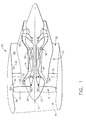
- FIG. 1 is a cross-sectional schematic illustration of an exemplary gas turbine engine assembly 10 having a longitudinal axis 11.
- Gas turbine engine assembly 10 includes a fan assembly 12 and a core gas turbine engine 13.
- Core gas turbine engine 13 includes a high pressure compressor 14, a combustor 16, and a high pressure turbine 18.
- gas turbine engine assembly 10 also includes a low pressure turbine 20, and a multi-stage booster compressor 32, and a splitter 34 that substantially circumscribes booster 32.
- Fan assembly 12 includes an array of fan blades 24 extending radially outward from a rotor disk 26, the forward portion of which is enclosed by a streamlined spinner 25.
- Gas turbine engine assembly 10 has an intake side 28 and an exhaust side 30.
- Fan assembly 12, booster 22, and turbine 20 are coupled together by a first rotor shaft and compressor 14 and turbine 18 are coupled together by a second rotor shaft 22.
- the compressed air that is discharged from booster 32 is channeled through compressor 14 wherein the airflow is further compressed and delivered to combustor 16.
- Hot products of combustion (not shown in Figure 1 ) from combustor 16 are utilized to drive turbines 18 and 20, and turbine 20 is utilized to drive fan assembly 12 and booster 32 by way of shaft 21.
- Gas turbine engine assembly 10 is operable at a range of operating conditions between design operating conditions and off-design operating conditions.
- a second portion 52 of the airflow discharged from fan assembly 12 is channeled through a bypass duct 40 to bypass a portion of the airflow from fan assembly 12 around core gas turbine engine 13. More specifically, bypass duct 40 extends between a fan casing or shroud 36 and splitter 34. Accordingly, a first portion 50 of the airflow from fan assembly 12 is channeled through booster 32 and then into compressor 14 as described above, and a second portion 52 of the airflow from fan assembly 12 is channeled through bypass duct 40 to provide thrust for an aircraft, for example.
- Splitter 34 divides the incoming airflow into first and second portions 50 and 52, respectively.
- Gas turbine engine assembly 10 also includes a fan frame assembly 60 to provide structural support for fan assembly 12 and is also utilized to couple fan assembly 12 to core gas turbine engine 13.
- Fan frame assembly 60 includes a plurality of outlet guide vanes 70 that extend substantially radially between a radially outer mounting flange and a radially inner mounting flange and are circumferentially-spaced within bypass duct 40.
- Fan frame assembly 60 may also include a plurality of struts that are coupled between a radially outer mounting flange and a radially inner mounting flange.
- fan frame assembly 60 is fabricated in arcuate segments in which flanges are coupled to outlet guide vanes 70 and struts.
- outlet guide vanes and struts are coupled coaxially within bypass duct 40.
- outlet guide vanes 70 may be coupled downstream from struts within bypass duct 40.
- Fan frame assembly 60 is one of various frame and support assemblies of gas turbine engine assembly 10 that are used to facilitate maintaining an orientation of various components within gas turbine engine assembly 10. More specifically, such frame and support assemblies interconnect stationary components and provide rotor bearing supports. Fan frame assembly 60 is coupled downstream from fan assembly 12 within bypass duct 40 such that outlet guide vanes 70 and struts are circumferentially-spaced around the outlet of fan assembly 12 and extend across the airflow path discharged from fan assembly 12.
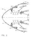
- FIG 2 is a partial cross-sectional elevational view of the forward portion of an exemplary aircraft gas turbine engine such as depicted in Figure 1 .
- a fairing 80 has been installed on the core gas turbine engine 13 in place of the spinner 25 and the fan blades 24 which have been removed and stored separately for transportation.
- the fairing 80 is of two-piece construction, comprising an inner portion 82 and an outer portion 84. Inner portion 82 and outer portion 84 are joined to one another as well as to the fan rotor 26 by bolts or other suitable fasteners 88 and suitably located mounting holes provided in the fairing components.
- Mounting holes 27 in the fan rotor 26, such as may typically be used to fasten the spinner 25 in place, may be utilized to secure the fairing 80 via fasteners 88.
- the fairing may be of one-piece (i.e., unitary) construction or multi-piece (i.e., two or more pieces) construction.
- the fairing 80 has a generally streamlined shape, typically of rounded conical or bullet-shaped design, to minimize drag on the engine during transport.
- the elements of the fairing are sized, shaped, and adapted to suit the characteristics of the particular engine application desired.
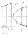
- Figure 3 is a cross-sectional elevational view of the fairing 80, similar to the view of Figure 2 but showing the fairing 80 in a disassembled condition and depicting the relationship of inner and outer portions 82 and 84, respectively.
- the outer portion 84 is of annular configuration and surrounds and is secured to the inner portion 82.
- an annular seal 86 which may be formed from rubber, foam, plastic, or other conformable material, which abuts and forms a substantially if not fully airtight seal against splitter 34 when the fairing 80 is installed on the core gas turbine engine 13.
- the annular seal 86 is integrally formed with the fairing 80, such as wherein the fairing 80 is formed from a material which is suitably compliant so as to conform to and sealingly engage the splitter 34.
- the fairing 80 is installed after removing and separately storing the spinner 25 and fan blades 24.
- the inner portion 82 of the fairing 80 is installed on the fan rotor 26 via mounting holes 27 and a plurality of fasteners 88.
- the outer portion of the fairing 84 is then installed over and around the inner portion 82 and is fastened to the inner portion 82 via fasteners 88.
- outer portion 84 moves axially toward the core gas turbine engine and the annular seal 86 comes into contact with and sealingly engages the forward portion of the splitter 34, so as to seal the opening of the booster 32 and prevent introduction of moisture, contaminants, and airflow into the booster 32 and thus into the core gas turbine engine 13.
- the process of securing the fairing 80 to the core gas turbine engine is a two phase operation wherein the first portion is secured first, followed by the second portion.
- the fairing 80 prevents air from flowing through the booster 32 during flight and imparting any rotational forces to the booster 32 (and any other rotating turbomachinery or accessories which share shaft 21 with booster 32). Air is also prevented from flowing through the compressor 14, as well as through both high pressure turbine 18 and low pressure turbine 20, and thereby avoiding imparting any rotational forces to those components (and any other rotating turbomachinery or accessories connected to shafts 21 or 22).
- the sealing engagement of the fairing 80 with the splitter 34 coupled with the mechanical engagement of the fairing 80 with the fan rotor 26 provides mechanical resistance to rotation for fan rotor 26 and any other components within the core gas turbine engine 13 which are associated with the shaft 21 to which the fan rotor 26 is attached.
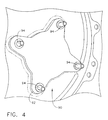
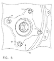
- Borescope motoring pad 90 is a location where a coverplate 92 can be removed via fasteners 94 (such as bolts, pins, screws, or other fasteners) to expose a socket 96 which is adapted for engagement by a tool (such as a 1 ⁇ 2 inch square drive ratchet, wrench, or bar) or a motorized drive assembly to rotate the core gas turbine engine 13 through a suitable gearbox assembly.
- a tool such as a 1 ⁇ 2 inch square drive ratchet, wrench, or bar
- a motorized drive assembly to rotate the core gas turbine engine 13 through a suitable gearbox assembly.
- a rotor lock 91 of suitable configuration for the particular engine application may be utilized.
- a rotor lock has suitable mounting holes 93, a seal 95, and a knob 97 of suitable configuration to engage the socket 96.
- the rotor lock 91 may be installed on the borescope motoring pad 90, engaging the socket 96 and sealing the opening via seal 95, and secured in place via fasteners 94, thereby mechanically preventing rotation of the socket 96 and all other rotating parts mechanically coupled to the socket 96.
- Rotor locks such as rotor lock 90 may be fabricated of any suitable material, such as metallic or composite materials, having suitable strength to resist turning motion of the socket 96.
- the fairing 80 may be a fiberglass material, a graphite material, a carbon material, a ceramic material, an aromatic polyamid material such as KEVLAR, a thin metallic material such as, but not limited to, titanium, aluminum, and/or a Metal Matrix Composite (MMC) material, and/or mixtures thereof.
- Any suitable thermosetting polymeric resin can be used in forming fairing 80, for example, vinyl ester resin, polyester resins, acrylic resins, epoxy resins, polyurethane resins, bismalimide resin, and mixtures thereof.
- the material is selected such that an exterior surface of fairing 80 is resistant to wear and or damage that may be caused by foreign objects ingested into gas turbine engine assembly 10. Alternate fairing configurations may use a thin metal wrap over a composite fairing to protect against such wear or damage.
Landscapes
- Engineering & Computer Science (AREA)
- Chemical & Material Sciences (AREA)
- Combustion & Propulsion (AREA)
- Mechanical Engineering (AREA)
- General Engineering & Computer Science (AREA)
- Aviation & Aerospace Engineering (AREA)
- Transportation (AREA)
- Manufacturing & Machinery (AREA)
- Structures Of Non-Positive Displacement Pumps (AREA)
- Turbine Rotor Nozzle Sealing (AREA)
Claims (9)
- Kit de carénage à utiliser avec un moteur à turbine à gaz, ledit moteur ayant un corps de moteur à turbine à gaz (13), un rotor de soufflante (26), et une pluralité d'aubes externes de soufflante (24) fixées audit rotor de soufflante (26) et alimentées par ledit corps de moteur à turbine à gaz (13), ledit corps de moteur à turbine à gaz (13) ayant un séparateur annulaire (34) pour diriger une partie d'un écoulement d'air entrant dans ledit corps de moteur à turbine à gaz (13), ledit kit de carénage comprenant :un carénage (80) ; etune pluralité de fixations (88) pour fixer ledit carénage (80) audit corps de moteur à turbine à gaz (13) ; caractérisé en ce queun joint d'étanchéité adaptable (86) est prévu pour rendre étanche les surfaces d'accouplement dudit carénage (80) et dudit corps de moteur à turbine à gaz (13), et ledit carénage (80) comprend une première partie (82) destinée à être fixée audit rotor de soufflante (26) et une seconde partie annulaire (84) qui entoure et est fixée à ladite première partie (82).
- Kit de carénage selon la revendication 1, dans lequel ledit carénage (80) a une forme aérodynamique.
- Kit de carénage selon l'une quelconque des précédentes revendications, dans lequel ledit carénage (80) a une structure formée de plusieurs pièces.
- Kit de carénage selon l'une quelconque des précédentes revendications, dans lequel ledit carénage (80) peut être fixé audit séparateur (34).
- Kit de carénage selon l'une quelconque des précédentes revendications, dans lequel ledit carénage (80) peut être fixé a un rotor de soufflante (26).
- Kit de carénage selon l'une quelconque des précédentes revendications, dans lequel ledit carénage peut former une étanchéité et empêcher un écoulement d'air à travers ledit corps de moteur à turbine à gaz (13).
- Kit de carénage selon l'une quelconque des précédentes revendications, dans lequel ladite seconde partie (84) peut être mise en contact étanche avec ledit séparateur (34) quand elle est fixée à ladite première partie (82).
- Kit de carénage selon l'une quelconque des précédentes revendications, dans lequel ledit carénage (80) est conçu de manière à pouvoir offrir une résistance mécanique à la rotation des composants à l'intérieur dudit corps de moteur à turbine à gaz (13).
- Kit de carénage selon l'une quelconque des précédentes revendications, dans lequel ledit kit de carénage comprend en outre un dispositif de blocage de rotor (91) pouvant empêcher la rotation des composants à l'intérieur dudit corps de moteur à turbine à gaz (13).
Applications Claiming Priority (1)
| Application Number | Priority Date | Filing Date | Title |
|---|---|---|---|
| US11/966,165 US20100047077A1 (en) | 2007-12-28 | 2007-12-28 | Ferry Flight Engine Fairing Kit |
Publications (3)
| Publication Number | Publication Date |
|---|---|
| EP2075436A2 EP2075436A2 (fr) | 2009-07-01 |
| EP2075436A3 EP2075436A3 (fr) | 2009-07-08 |
| EP2075436B1 true EP2075436B1 (fr) | 2012-08-08 |
Family
ID=40278779
Family Applications (1)
| Application Number | Title | Priority Date | Filing Date |
|---|---|---|---|
| EP08172249A Expired - Fee Related EP2075436B1 (fr) | 2007-12-28 | 2008-12-19 | Cône d'entrée pour une turbine à gaz |
Country Status (4)
| Country | Link |
|---|---|
| US (1) | US20100047077A1 (fr) |
| EP (1) | EP2075436B1 (fr) |
| JP (1) | JP2009185804A (fr) |
| CA (1) | CA2647753A1 (fr) |
Families Citing this family (12)
| Publication number | Priority date | Publication date | Assignee | Title |
|---|---|---|---|---|
| US20100043228A1 (en) * | 2007-12-28 | 2010-02-25 | James Lloyd Daniels | Method of Preparing an Engine for Ferry Flight |
| US8814512B2 (en) * | 2011-07-05 | 2014-08-26 | United Technologies Corporation | Fan disk apparatus and method |
| JP5863321B2 (ja) * | 2011-08-08 | 2016-02-16 | 三菱重工コンプレッサ株式会社 | 回転機械の治具及び回転機械の輸送方法 |
| US9759129B2 (en) | 2012-12-28 | 2017-09-12 | United Technologies Corporation | Removable nosecone for a gas turbine engine |
| US9540939B2 (en) * | 2012-12-28 | 2017-01-10 | United Technologies Corporation | Gas turbine engine with attached nosecone |
| US9206742B2 (en) * | 2012-12-29 | 2015-12-08 | United Technologies Corporation | Passages to facilitate a secondary flow between components |
| US10047625B2 (en) * | 2013-03-15 | 2018-08-14 | United Technologies Corporation | Fan blade root integrated sealing solution |
| CN103216360B (zh) * | 2013-04-07 | 2016-03-02 | 朱晓义 | 涡轮发动机及动力装置 |
| WO2015084460A2 (fr) * | 2013-10-02 | 2015-06-11 | United Technologies Corporation | Joint d'etancheite de recirculation destine a etre utilise dans une turbine a gaz |
| US10267177B2 (en) * | 2015-02-09 | 2019-04-23 | Rolls-Royce North American Technologies Inc. | Turbine assembly having a rotor system lock |
| CN109250149B (zh) * | 2018-09-26 | 2023-09-19 | 中国空气动力研究与发展中心超高速空气动力研究所 | 用于吸气式高超飞行器整流罩分离模拟的风洞试验装置 |
| CN116085076B (zh) * | 2023-02-13 | 2025-08-01 | 中国航发沈阳发动机研究所 | 一种航空发动机进气机匣结构及其装配方法 |
Family Cites Families (17)
| Publication number | Priority date | Publication date | Assignee | Title |
|---|---|---|---|---|
| US3000533A (en) * | 1959-04-24 | 1961-09-19 | William E Rockhill | Engine inlet plug |
| US3646980A (en) * | 1970-06-15 | 1972-03-07 | Peterson Products Of San Mateo | Jet engine cowl cover |
| US3871844A (en) * | 1973-09-28 | 1975-03-18 | Sr Frank F Calvin | Screen apparatus for air inlet |
| US3990814A (en) * | 1975-06-25 | 1976-11-09 | United Technologies Corporation | Spinner |
| GB1557856A (en) * | 1977-04-20 | 1979-12-12 | Rolls Royce | Spinner or nose bullet |
| GB1594354A (en) * | 1977-06-02 | 1981-07-30 | Rolls Royce | Device for turning the rotor of a gas turbine engine |
| US4209149A (en) * | 1977-12-27 | 1980-06-24 | Boeing Commercial Airplane Company | Contracted inlet for jet engine being transported as cargo |
| US4314681A (en) * | 1979-08-31 | 1982-02-09 | General Electric Company | Drag-reducing component |
| CA2021087A1 (fr) * | 1989-09-07 | 1991-03-08 | Eugene J. Antuna | Methode de transport d'un reacteur a double flux tres eleve avec soufflante et capot |
| US5224341A (en) * | 1992-01-06 | 1993-07-06 | United Technologies Corporation | Separable fan strut for a gas turbofan powerplant |
| US5833435A (en) * | 1996-12-24 | 1998-11-10 | United Technologies Corporation | Inlet nose cone assembly and method for repairing the assembly |
| FR2851787B1 (fr) * | 2003-02-28 | 2005-05-20 | Airbus France | Dispositif de protection d'une structure d'entree d'air d'un moteur a reaction |
| US6887043B2 (en) * | 2003-03-28 | 2005-05-03 | General Electric Company | Methods and apparatus for assembling gas turbine engines |
| US6905309B2 (en) * | 2003-08-28 | 2005-06-14 | General Electric Company | Methods and apparatus for reducing vibrations induced to compressor airfoils |
| FR2866068B1 (fr) * | 2004-02-06 | 2006-07-07 | Snecma Moteurs | Turboreacteur a soufflante solidaire d'un arbre d'entrainement supporte par un premier et un deuxieme paliers |
| US7721526B2 (en) * | 2006-06-28 | 2010-05-25 | Ishikawajima-Harima Heavy Industries Co., Ltd. | Turbofan engine |
| US20100043228A1 (en) * | 2007-12-28 | 2010-02-25 | James Lloyd Daniels | Method of Preparing an Engine for Ferry Flight |
-
2007
- 2007-12-28 US US11/966,165 patent/US20100047077A1/en not_active Abandoned
-
2008
- 2008-12-19 EP EP08172249A patent/EP2075436B1/fr not_active Expired - Fee Related
- 2008-12-22 JP JP2008324863A patent/JP2009185804A/ja active Pending
- 2008-12-23 CA CA002647753A patent/CA2647753A1/fr not_active Abandoned
Also Published As
| Publication number | Publication date |
|---|---|
| US20100047077A1 (en) | 2010-02-25 |
| JP2009185804A (ja) | 2009-08-20 |
| CA2647753A1 (fr) | 2009-06-28 |
| EP2075436A2 (fr) | 2009-07-01 |
| EP2075436A3 (fr) | 2009-07-08 |
Similar Documents
| Publication | Publication Date | Title |
|---|---|---|
| EP2075436A2 (fr) | Cône d'entrée pour une turbine à gaz | |
| EP3415437B1 (fr) | Moteur à turbine contrarotatif de soufflante arrière | |
| EP1852595B1 (fr) | Inverseur de poussée pour moteurs d'avion | |
| US20080072569A1 (en) | Guide vane and method of fabricating the same | |
| US20080159856A1 (en) | Guide vane and method of fabricating the same | |
| US20080159851A1 (en) | Guide Vane and Method of Fabricating the Same | |
| US20140252160A1 (en) | Reverse flow gas turbine engine removable core | |
| GB2536796A (en) | Unducted fan for an aircraft turbine engine | |
| US10767566B2 (en) | Electric propulsion motor cooling system and method | |
| CN110341969B (zh) | 用于机身安装的动力装置的风扇整流罩的闩锁装置 | |
| US20210396147A1 (en) | Electric module for an aircraft fan comprising blades with improved attachment | |
| US10436151B2 (en) | Modular fan for a gas turbine engine | |
| US20150308381A1 (en) | Drag link assembly including buried drag link fitting | |
| EP2075420B1 (fr) | Procédé de préparation d'un moteur pour le transport | |
| US11548652B2 (en) | Nacelle | |
| US11421592B2 (en) | Gas turbine engine | |
| US20180010616A1 (en) | Strut assembly for an aircraft engine | |
| US10858956B2 (en) | Gas turbine engine keel beam | |
| US9932846B2 (en) | Aeroengine sealing arrangement | |
| EP3647562B1 (fr) | Procédé de remplacement d'un module | |
| US20200056541A1 (en) | Fan blade removal method and tooling | |
| US20190382122A1 (en) | Gas turbine engine | |
| EP3434596B1 (fr) | Nacelle | |
| US20250093030A1 (en) | Multi-piece injector nozzle for a turbine engine | |
| Day | C56-50A Engines |
Legal Events
| Date | Code | Title | Description |
|---|---|---|---|
| PUAI | Public reference made under article 153(3) epc to a published international application that has entered the european phase |
Free format text: ORIGINAL CODE: 0009012 |
|
| PUAL | Search report despatched |
Free format text: ORIGINAL CODE: 0009013 |
|
| AK | Designated contracting states |
Kind code of ref document: A2 Designated state(s): AT BE BG CH CY CZ DE DK EE ES FI FR GB GR HR HU IE IS IT LI LT LU LV MC MT NL NO PL PT RO SE SI SK TR |
|
| AX | Request for extension of the european patent |
Extension state: AL BA MK RS |
|
| AK | Designated contracting states |
Kind code of ref document: A3 Designated state(s): AT BE BG CH CY CZ DE DK EE ES FI FR GB GR HR HU IE IS IT LI LT LU LV MC MT NL NO PL PT RO SE SI SK TR |
|
| AX | Request for extension of the european patent |
Extension state: AL BA MK RS |
|
| 17P | Request for examination filed |
Effective date: 20100108 |
|
| AKX | Designation fees paid |
Designated state(s): DE FR GB |
|
| 17Q | First examination report despatched |
Effective date: 20100311 |
|
| REG | Reference to a national code |
Ref country code: DE Ref legal event code: R079 Ref document number: 602008017766 Country of ref document: DE Free format text: PREVIOUS MAIN CLASS: F02C0007040000 Ipc: F02C0007000000 |
|
| RIC1 | Information provided on ipc code assigned before grant |
Ipc: F02C 7/20 20060101ALI20111214BHEP Ipc: F01D 25/28 20060101ALI20111214BHEP Ipc: B64F 1/00 20060101ALI20111214BHEP Ipc: B64F 5/00 20060101ALI20111214BHEP Ipc: F02K 3/00 20060101ALI20111214BHEP Ipc: F02C 7/00 20060101AFI20111214BHEP |
|
| GRAP | Despatch of communication of intention to grant a patent |
Free format text: ORIGINAL CODE: EPIDOSNIGR1 |
|
| GRAS | Grant fee paid |
Free format text: ORIGINAL CODE: EPIDOSNIGR3 |
|
| GRAA | (expected) grant |
Free format text: ORIGINAL CODE: 0009210 |
|
| AK | Designated contracting states |
Kind code of ref document: B1 Designated state(s): DE FR GB |
|
| REG | Reference to a national code |
Ref country code: GB Ref legal event code: FG4D |
|
| REG | Reference to a national code |
Ref country code: DE Ref legal event code: R096 Ref document number: 602008017766 Country of ref document: DE Effective date: 20120927 |
|
| PLBE | No opposition filed within time limit |
Free format text: ORIGINAL CODE: 0009261 |
|
| STAA | Information on the status of an ep patent application or granted ep patent |
Free format text: STATUS: NO OPPOSITION FILED WITHIN TIME LIMIT |
|
| REG | Reference to a national code |
Ref country code: DE Ref legal event code: R119 Ref document number: 602008017766 Country of ref document: DE |
|
| 26N | No opposition filed |
Effective date: 20130510 |
|
| GBPC | Gb: european patent ceased through non-payment of renewal fee |
Effective date: 20121219 |
|
| REG | Reference to a national code |
Ref country code: DE Ref legal event code: R097 Ref document number: 602008017766 Country of ref document: DE Effective date: 20130510 |
|
| REG | Reference to a national code |
Ref country code: FR Ref legal event code: ST Effective date: 20130830 |
|
| PG25 | Lapsed in a contracting state [announced via postgrant information from national office to epo] |
Ref country code: DE Free format text: LAPSE BECAUSE OF NON-PAYMENT OF DUE FEES Effective date: 20130702 |
|
| REG | Reference to a national code |
Ref country code: DE Ref legal event code: R119 Ref document number: 602008017766 Country of ref document: DE Effective date: 20130702 |
|
| PG25 | Lapsed in a contracting state [announced via postgrant information from national office to epo] |
Ref country code: GB Free format text: LAPSE BECAUSE OF NON-PAYMENT OF DUE FEES Effective date: 20121219 Ref country code: FR Free format text: LAPSE BECAUSE OF NON-PAYMENT OF DUE FEES Effective date: 20130102 |