EP2075440B1 - Procédé et dispositif pour le contrôle d'une centrale à turbine à gaz - Google Patents
Procédé et dispositif pour le contrôle d'une centrale à turbine à gaz Download PDFInfo
- Publication number
- EP2075440B1 EP2075440B1 EP07425849A EP07425849A EP2075440B1 EP 2075440 B1 EP2075440 B1 EP 2075440B1 EP 07425849 A EP07425849 A EP 07425849A EP 07425849 A EP07425849 A EP 07425849A EP 2075440 B1 EP2075440 B1 EP 2075440B1
- Authority
- EP
- European Patent Office
- Prior art keywords
- flow rate
- diffusion
- premixing
- theoretical
- combustion chamber
- Prior art date
- Legal status (The legal status is an assumption and is not a legal conclusion. Google has not performed a legal analysis and makes no representation as to the accuracy of the status listed.)
- Not-in-force
Links
- 238000000034 method Methods 0.000 title claims description 13
- 238000009792 diffusion process Methods 0.000 claims description 101
- 238000002485 combustion reaction Methods 0.000 claims description 45
- 230000001276 controlling effect Effects 0.000 claims description 7
- 230000001105 regulatory effect Effects 0.000 claims description 3
- 230000004913 activation Effects 0.000 claims description 2
- 230000003213 activating effect Effects 0.000 claims 2
- 238000010586 diagram Methods 0.000 description 6
- 230000007704 transition Effects 0.000 description 6
- 239000000446 fuel Substances 0.000 description 5
- 238000011144 upstream manufacturing Methods 0.000 description 4
- 230000010355 oscillation Effects 0.000 description 3
- 238000004519 manufacturing process Methods 0.000 description 2
- 230000009471 action Effects 0.000 description 1
- 230000009849 deactivation Effects 0.000 description 1
- 238000012986 modification Methods 0.000 description 1
- 230000004048 modification Effects 0.000 description 1
Images



Classifications
-
- F—MECHANICAL ENGINEERING; LIGHTING; HEATING; WEAPONS; BLASTING
- F02—COMBUSTION ENGINES; HOT-GAS OR COMBUSTION-PRODUCT ENGINE PLANTS
- F02C—GAS-TURBINE PLANTS; AIR INTAKES FOR JET-PROPULSION PLANTS; CONTROLLING FUEL SUPPLY IN AIR-BREATHING JET-PROPULSION PLANTS
- F02C9/00—Controlling gas-turbine plants; Controlling fuel supply in air- breathing jet-propulsion plants
- F02C9/26—Control of fuel supply
- F02C9/28—Regulating systems responsive to plant or ambient parameters, e.g. temperature, pressure, rotor speed
-
- F—MECHANICAL ENGINEERING; LIGHTING; HEATING; WEAPONS; BLASTING
- F02—COMBUSTION ENGINES; HOT-GAS OR COMBUSTION-PRODUCT ENGINE PLANTS
- F02C—GAS-TURBINE PLANTS; AIR INTAKES FOR JET-PROPULSION PLANTS; CONTROLLING FUEL SUPPLY IN AIR-BREATHING JET-PROPULSION PLANTS
- F02C7/00—Features, components parts, details or accessories, not provided for in, or of interest apart form groups F02C1/00 - F02C6/00; Air intakes for jet-propulsion plants
- F02C7/22—Fuel supply systems
-
- F—MECHANICAL ENGINEERING; LIGHTING; HEATING; WEAPONS; BLASTING
- F02—COMBUSTION ENGINES; HOT-GAS OR COMBUSTION-PRODUCT ENGINE PLANTS
- F02C—GAS-TURBINE PLANTS; AIR INTAKES FOR JET-PROPULSION PLANTS; CONTROLLING FUEL SUPPLY IN AIR-BREATHING JET-PROPULSION PLANTS
- F02C7/00—Features, components parts, details or accessories, not provided for in, or of interest apart form groups F02C1/00 - F02C6/00; Air intakes for jet-propulsion plants
- F02C7/22—Fuel supply systems
- F02C7/228—Dividing fuel between various burners
-
- F—MECHANICAL ENGINEERING; LIGHTING; HEATING; WEAPONS; BLASTING
- F02—COMBUSTION ENGINES; HOT-GAS OR COMBUSTION-PRODUCT ENGINE PLANTS
- F02C—GAS-TURBINE PLANTS; AIR INTAKES FOR JET-PROPULSION PLANTS; CONTROLLING FUEL SUPPLY IN AIR-BREATHING JET-PROPULSION PLANTS
- F02C7/00—Features, components parts, details or accessories, not provided for in, or of interest apart form groups F02C1/00 - F02C6/00; Air intakes for jet-propulsion plants
- F02C7/22—Fuel supply systems
- F02C7/232—Fuel valves; Draining valves or systems
-
- F—MECHANICAL ENGINEERING; LIGHTING; HEATING; WEAPONS; BLASTING
- F02—COMBUSTION ENGINES; HOT-GAS OR COMBUSTION-PRODUCT ENGINE PLANTS
- F02C—GAS-TURBINE PLANTS; AIR INTAKES FOR JET-PROPULSION PLANTS; CONTROLLING FUEL SUPPLY IN AIR-BREATHING JET-PROPULSION PLANTS
- F02C9/00—Controlling gas-turbine plants; Controlling fuel supply in air- breathing jet-propulsion plants
- F02C9/26—Control of fuel supply
-
- F—MECHANICAL ENGINEERING; LIGHTING; HEATING; WEAPONS; BLASTING
- F02—COMBUSTION ENGINES; HOT-GAS OR COMBUSTION-PRODUCT ENGINE PLANTS
- F02C—GAS-TURBINE PLANTS; AIR INTAKES FOR JET-PROPULSION PLANTS; CONTROLLING FUEL SUPPLY IN AIR-BREATHING JET-PROPULSION PLANTS
- F02C9/00—Controlling gas-turbine plants; Controlling fuel supply in air- breathing jet-propulsion plants
- F02C9/26—Control of fuel supply
- F02C9/32—Control of fuel supply characterised by throttling of fuel
- F02C9/34—Joint control of separate flows to main and auxiliary burners
-
- F—MECHANICAL ENGINEERING; LIGHTING; HEATING; WEAPONS; BLASTING
- F02—COMBUSTION ENGINES; HOT-GAS OR COMBUSTION-PRODUCT ENGINE PLANTS
- F02C—GAS-TURBINE PLANTS; AIR INTAKES FOR JET-PROPULSION PLANTS; CONTROLLING FUEL SUPPLY IN AIR-BREATHING JET-PROPULSION PLANTS
- F02C9/00—Controlling gas-turbine plants; Controlling fuel supply in air- breathing jet-propulsion plants
- F02C9/26—Control of fuel supply
- F02C9/40—Control of fuel supply specially adapted to the use of a special fuel or a plurality of fuels
-
- F—MECHANICAL ENGINEERING; LIGHTING; HEATING; WEAPONS; BLASTING
- F23—COMBUSTION APPARATUS; COMBUSTION PROCESSES
- F23N—REGULATING OR CONTROLLING COMBUSTION
- F23N1/00—Regulating fuel supply
- F23N1/02—Regulating fuel supply conjointly with air supply
- F23N1/022—Regulating fuel supply conjointly with air supply using electronic means
-
- F—MECHANICAL ENGINEERING; LIGHTING; HEATING; WEAPONS; BLASTING
- F23—COMBUSTION APPARATUS; COMBUSTION PROCESSES
- F23R—GENERATING COMBUSTION PRODUCTS OF HIGH PRESSURE OR HIGH VELOCITY, e.g. GAS-TURBINE COMBUSTION CHAMBERS
- F23R3/00—Continuous combustion chambers using liquid or gaseous fuel
- F23R3/02—Continuous combustion chambers using liquid or gaseous fuel characterised by the air-flow or gas-flow configuration
- F23R3/26—Controlling the air flow
-
- F—MECHANICAL ENGINEERING; LIGHTING; HEATING; WEAPONS; BLASTING
- F23—COMBUSTION APPARATUS; COMBUSTION PROCESSES
- F23R—GENERATING COMBUSTION PRODUCTS OF HIGH PRESSURE OR HIGH VELOCITY, e.g. GAS-TURBINE COMBUSTION CHAMBERS
- F23R3/00—Continuous combustion chambers using liquid or gaseous fuel
- F23R3/28—Continuous combustion chambers using liquid or gaseous fuel characterised by the fuel supply
- F23R3/34—Feeding into different combustion zones
-
- F—MECHANICAL ENGINEERING; LIGHTING; HEATING; WEAPONS; BLASTING
- F05—INDEXING SCHEMES RELATING TO ENGINES OR PUMPS IN VARIOUS SUBCLASSES OF CLASSES F01-F04
- F05D—INDEXING SCHEME FOR ASPECTS RELATING TO NON-POSITIVE-DISPLACEMENT MACHINES OR ENGINES, GAS-TURBINES OR JET-PROPULSION PLANTS
- F05D2270/00—Control
- F05D2270/01—Purpose of the control system
- F05D2270/08—Purpose of the control system to produce clean exhaust gases
- F05D2270/083—Purpose of the control system to produce clean exhaust gases by monitoring combustion conditions
-
- F—MECHANICAL ENGINEERING; LIGHTING; HEATING; WEAPONS; BLASTING
- F23—COMBUSTION APPARATUS; COMBUSTION PROCESSES
- F23N—REGULATING OR CONTROLLING COMBUSTION
- F23N2237/00—Controlling
- F23N2237/02—Controlling two or more burners
-
- F—MECHANICAL ENGINEERING; LIGHTING; HEATING; WEAPONS; BLASTING
- F23—COMBUSTION APPARATUS; COMBUSTION PROCESSES
- F23N—REGULATING OR CONTROLLING COMBUSTION
- F23N2241/00—Applications
- F23N2241/20—Gas turbines
Definitions
- the present Invention relates to a device and to a method for controlling a gas-turbine plant.
- the present invention regards a device and a method for controlling a gas-turbine plant that can operate with gas oil.
- a gas-turbine plant that can operate with gas oil.
- An example of a known plant is disclosed in the document US-A-2004/0255594 .
- a known type of gas-turbine plant comprises a combustion chamber that can be supplied with gas or gas oil.
- the plant comprises a gas supply circuit and a gas-oil supply circuit for the combustion chamber and a device for controlling the gas-turbine plant.
- the gas-oil supply circuit comprises a diffusion supply line and a premixing supply line and can operate in a purely diffusion mode or in a mixed diffusion and premixing mode.
- An aim of the present invention is to provide a device for controlling a gas turbine that is free from the drawbacks of the known art highlighted herein; in particular, an aim of the invention is to provide a control device capable of eliminating the flame instabilities and the oscillations in the power emitted.
- the present invention regards a method and a device for controlling a gas-turbine plant as specified in Claims 1 and 6, respectively.
- FIG. 1 Represented in Figure 1 is a gas-turbine plant 1 for the production of electrical energy comprising a control device 2, a compressor 3, a combustion chamber 4, a supply circuit 5 for supplying the combustion chamber 4, and a turbine 6, which drives a generator 7, which is mounted on the same shaft 8 as the turbine 6 and is designed to generate a power P.
- the combustion chamber 4 is preferably of the annular type and can be supplied both with gas oil and with gas.
- the combustion chamber 4 comprises a plurality of burners, for example twenty-four, which are supplied by the supply circuit 5.
- the supply circuit 5 comprises a gas supply circuit 10 and a gas-oil supply circuit 11.
- a variant of the present invention envisages that the supply circuit 5 comprises just the gas-oil supply circuit.
- the gas-oil supply circuit 11 comprises a diffusion supply line 13 and a premixing supply line 14.
- the diffusion supply line 13 comprises a delivery duct 15, set along which is a delivery valve 16, and a return duct 17, set along which is a return valve 18.
- the delivery valve 16 and the return valve 18 are regulated by the control device 2.
- the pressure of the gas oil assumes different values.
- the pressure upstream of the delivery valve 15 assumes a first value P1m, whilst downstream of the delivery valve it assumes a second value P1v.
- the combustion chamber 4 is supplied by the diffusion supply line 13 with a diffusion flow rate Q2 equal to the difference between the delivery diffusion flow rate Q1 and the return diffusion flow rate Q3.
- control device 2 determines a lift h1 of the delivery valve 15 and a lift h3 of the return valve 18.
- premixing supply line 14 there circulates a premixing flow rate Q4 of gas oil and there is set a premixing delivery valve 19, across which there is a pressure drop ⁇ P4.
- premixing delivery valve 19 is controlled by the control device 2, which determines a lift h4 of the premixing delivery valve 19.
- the combustion chamber 4 is thus supplied with a flow rate equal to the diffusion flow rate Q2 in the diffusion-only operating mode and with a flow rate equal to the sum of the diffusion flow rate Q2 and of the premixing flow rate Q4 in the mixed operating mode.
- control device 2 comprises a power regulator 20, a fuel distributor 21, a diffusion-regulation block 22, and a premixing-regulation block 23.
- the power regulator 20, on the basis of a power requirement PR calculates a required flow rate QR.
- the fuel distributor 21 regulates the type of fuel used for supplying the combustion chamber 4.
- the fuel distributor 21 issues a gas/gas-oil proportion signal Fprop, which is comprised between 0 and 1 and is indicative of the gas supply mode or of the gas-oil supply mode.
- Fprop assumes values comprised between 0 and 1 and the combustion chamber 4 is supplied with gas and with gas oil simultaneously.
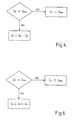
- the control device 2 moreover comprises a block 24 for calculating a theoretical regulation flow rate Q5 of gas oil to be supplied to the combustion chamber 4, a compensation block 25, connected to the diffusion-regulation block 22 and to the premixing-regulation block 23, and a premixing-activation block 26.
- the block 24 for calculating the theoretical flow rate Q5 receives at input the signal Fprop and the required flow rate QR, and calculates the theoretical regulation flow rate Q5 of gas oil to be supplied to the combustion chamber 4. In particular, the block 24 multiplies the required flow rate QR by the signal Fprop. In the case where the signal Fprop is equal to 1, i.e., in the mode of supply with just gas oil, the theoretical regulation flow rate Q5 coincides with the required flow rate QR.
- the block 24 converts the theoretical regulation flow rate Q5 into kg/sec.
- the theoretical regulation flow rate Q5 thus calculated is supplied to the diffusion-regulation block 22 and to the premixing-regulation block 23.
- the diffusion-regulation block 22 determines, on the basis of the theoretical regulation flow rate Q5, the lift h1 of the delivery valve 16 and the lift h3 of the return valve 18 of the diffusion supply line 13.
- the premixing-regulation block 23 determines, on the basis of the theoretical regulation flow rate Q5, the lift h4 of the premixing delivery valve 19.
- the diffusion-regulation block 22 comprises a block 27 for calculating the diffusion flow rate Q2, a block 28 for calculating the delivery diffusion flow rate Q1 and the return diffusion flow rate Q3, and a block 29 for calculating the valve lifts h1 and h3 of the delivery valve 16 and of the return valve 18.
- the premixing-regulation block 23 comprises a block 30 for calculating a theoretical premixing flow rate Q5', a block 31 for calculating the premixing flow rate Q4, and a block 32 for calculating the lift h4 of the premixing delivery valve 19.
- the block 27 for calculating the diffusion flow rate Q2 receives at input the theoretical regulation flow rate Q5, a minimum diffusion flow rate QDmin and the premixing flow rate Q4 supplied by the compensation block 25 only in given operating conditions, as will be seen in detail hereinafter.
- the minimum diffusion flow rate QDmin has a constant value defined a priori in the design stages of the control device 2.
- block 27 supplies a diffusion flow rate Q2 equal to the minimum diffusion flow rate QDmin if the theoretical regulation flow rate Q5 is lower than the minimum diffusion flow rate QDmin, whilst it calculates the diffusion flow rate Q2, subtracting from the theoretical regulation flow rate Q5 the premixing flow rate Q4 if the theoretical regulation flow rate Q5 is higher than the minimum diffusion flow rate QDmin.
- Block 27 is thus configured for guaranteeing a minimum diffusion flow rate QDmin in the diffusion supply line 13.
- the guarantee of a minimum diffusion flow rate QDmin is particularly advantageous in the steps of starting of the diffusion supply line 13, i.e., in the transition from the gas supply mode to the gas-oil supply mode.
- the theoretical regulation flow rate Q5 is zero, or almost, and the minimum diffusion flow rate QDmin guarantees a step increase in the flow rate introduced in the combustion chamber 4 substantially equal to the minimum diffusion flow rate QDmin.
- block 28 for calculating the delivery diffusion flow rate Q1 and the return diffusion flow rate Q3 receives at input the value of diffusion flow rate Q2 to be supplied to the combustion chamber 4 and calculates the delivery diffusion flow rate Q1 and the return diffusion flow rate Q3 so as to optimize the level of nebulizing of the gas oil within the combustion chamber 4, albeit guaranteeing the production of the power requirement PR.
- Block 28 determines a delivery diffusion flow rate Q1 such as to obtain a pressure drop ⁇ Pcm that is optimal for nebulizing the gas oil in the combustion chamber 4 according to the power P delivered.
- the diagram of Figure 5 represents on the abscissa the pressure drop ⁇ Pcr and on the ordinate the delivery diffusion flow rate Q1 and the diffusion flow rate Q2.
- the curve of the diagram designated by a dashed-and-dotted line represents the locus of the points at zero recirculation, where the delivery diffusion flow rate Q1 is equal to the diffusion flow rate Q2, and the return diffusion flow rate Q3 is consequently zero.
- the diagram is obtained by measuring experimentally different values of the delivery diffusion flow rate Q1 and the diffusion flow rate Q2 and the corresponding pressure drops ⁇ Pcm and ⁇ Pcr so as to obtain a series of working points.
- the coefficients a and ⁇ are obtained by solving, for each equation of the system given above, a system of three equations with three unknowns calculated in three different working points.
- the coefficients thus calculated are constants.
- block 29 for calculating the lifts h1 and h3 receives at input the delivery diffusion flow rate Q1, the return diffusion flow rate Q3, and the pressure drops ⁇ Pcm and ⁇ Pcr.
- block 29 calculates the pressure P1v downstream of the delivery valve 16 and the pressure P3m upstream of the return valve 18.
- block 29 calculates the lift h1 of the delivery valve 16 for an actuator (not illustrated in the attached figures) of the delivery valve 16.
- block 29 calculates the lift h3 of the return valve 18 for an actuator (not illustrated in the attached figures) of the return valve 18.
- the premixing-activation block 26 on the basis of the value of power requirement PR activates the premixing-regulation block 23 and sends to block 30 for calculating the theoretical premixing flow rate Q5' a premixing-diffusion proportion signal PremixProp comprised between 0 and 1.
- the premixing-activation block 26 activates selectively one between a diffusion operating mode and a mixed diffusion and premixing mode. In particular, when the signal PremixProp is zero, the mode of operation is by diffusion, whilst for values of the signal PremixProp different from zero, the mode of operation is mixed.
- the signal PremixProp is comprised between 0 and approximately 0.8 to prevent the combustion chamber 4 from being supplied by just the premixing supply line 14, which is insufficient for keeping the flame in the combustion chamber 4 stable.
- the diffusion supply line 13 represents in fact a sort of pilot flame for the combustion chamber 4.
- Block 30 for calculating the theoretical premixing flow rate Q5' receives at input the signal PremixProp from the premixing-activation block 26 and the theoretical regulation flow rate Q5 from block 24 and calculates the theoretical premixing flow rate Q5' as product between the signal premixProp and the theoretical regulation flow rate Q5.
- Block 31 for calculating the premixing flow rate Q4 receives at input the theoretical premixing flow rate Q5', a minimum premixing flow rate QPmin and a diffusion-compensation flow rate Qc coming from the compensation block 25.
- the diffusion-compensation flow rate Qc takes into account the flow rate contribution represented by the diffusion supply line 13.
- the minimum premixing flow rate QPmin has a constant value, defined a priori in the design stages of the control device 2.
- block 31 determines a premixing flow rate Q4 equal to the minimum premixing flow rate QPmin if the theoretical premixing flow rate Q5' is lower than the minimum premixing flow rate QPmin, whereas it determines the premixing flow rate Q4 by subtracting from the theoretical premixing flow rate Q5' the diffusion-compensation flow rate Qc if the theoretical premixing flow rate Q5' is greater than the minimum premixing flow rate QPmin.
- Block 31 is thus configured for guaranteeing a minimum premixing flow rate QPmin.
- the guarantee of a minimum premixing flow rate QPmin proves particularly advantageous in the steps of starting of the premixing supply line 14, i.e., in the transition from the diffusion operating mode to the mixed operating mode.
- the theoretical premixing flow rate Q5' is zero, or almost, given that signal PremixProp is substantially zero, and the minimum premixing flow rate QPmin guarantees a step increase in the flow rate circulating in the premixing supply line 14 equal to the minimum premixing flow rate QPmin.
- Block 32 calculates the lift h4 of the premixing delivery valve 19 starting from the premixing flow rate Q4 and the pressure drop ⁇ P4 measured across the premixing delivery valve 19.
- the lift h4 of the premixing delivery valve 19 will then be supplied to an actuator (not illustrated in the attached figures) of the premixing delivery valve 19.
- the compensation block 25 receives at input the diffusion flow rate Q2, the premixing flow rate Q4, the minimum premixing flow rate QPmin, the minimum diffusion flow rate QDmin, the theoretical regulation flow rate Q5, and the theoretical premixing flow rate Q5'.
- the compensation block 25 sends to block 27 for calculating the diffusion flow rate Q2 the premixing flow rate Q4 only when the operation in the mixed mode is active.
- the compensation block 25 moreover determines the diffusion-compensation flow rate Qc to be sent to block 31 for calculating the premixing flow rate Q4.
- the flow rate at input to the combustion chamber 4 does not vary. In this way, the emitted power P does not undergo variations and the stability of the flame in the combustion chamber 4 is moreover guaranteed.
Landscapes
- Engineering & Computer Science (AREA)
- Chemical & Material Sciences (AREA)
- Combustion & Propulsion (AREA)
- Mechanical Engineering (AREA)
- General Engineering & Computer Science (AREA)
- Feeding And Controlling Fuel (AREA)
- Control Of Turbines (AREA)
Claims (7)
- Procédé de commande d'une installation à turbine à gaz qui peut fonctionner avec le gasoil ou avec le gaz et le gasoil, comprenant les étapes qui consistent :à déterminer un débit de régulation théorique (Q5) de gasoil à alimenter à une chambre de combustion (4) de l'installation (1) sur la base d'une puissance requise (PR) pour l'installation (1) ;à déterminer un débit de diffusion (Q2) sur la base du débit de régulation théorique (Q5) ; età alimenter par diffusion le débit de diffusion (Q2) à la chambre de combustion (4) ; le débit de diffusion (Q2) étant égal à au moins un débit de diffusion minimal (QDmin) ;à activer sélectivement l'un d'un mode de fonctionnement par diffusion et d'un mode mixte de prémélange et de diffusion ;à déterminer, dans le mode de fonctionnement mixte, un débit de prémélange théorique (Q5') à alimenter avec prémélange à la chambre de combustion (4) sur la base du débit de régulation théorique (Q5) ;à déterminer un débit de prémélange (Q4) sur la base du débit de prémélange théorique (Q5') ; età alimenter par prémélange le débit de prémélange (Q4) à la chambre de combustion (4) ; le débit de prémélange (Q4) étant égal à au moins un débit de prémélange minimal (QPmin) ;le procédé étant caractérisé en ce que l'étape de détermination du débit de prémélange (Q4) comprend le fait de déterminer un débit de compensation de diffusion (Qc) et de calculer le débit de prémélange (Q4) comme étant la différence entre le débit de prémélange théorique (Q5') et le débit de compensation de diffusion (Qc) ; l'étape de détermination d'un débit de compensation de diffusion (Qc) comprenant le fait de soustraire le débit de prémélange théorique (Q5') et le débit de diffusion minimal (QDmin) du débit de régulation théorique (Q5), si la différence entre le débit de régulation théorique (Q5) et le débit de prémélange théorique (Q5') est inférieure au débit de diffusion minimal (QDmin).
- Procédé selon la revendication 1, caractérisé en ce que l'étape de détermination du débit de diffusion (Q2) comprend le fait de calculer la différence entre le débit de régulation théorique (Q5) et le débit de prémélange (Q4).
- Procédé selon la revendication 1 ou 2, caractérisé en ce que le débit de compensation de diffusion (Qc) est nul si la différence entre le débit de régulation théorique (Q5) et le débit de prémélange théorique (Q5') est supérieure au débit de diffusion minimal (QDmin).
- Procédé selon l'une quelconque des revendications précédentes, caractérisé en ce que l'étape d'alimentation par diffusion du débit de diffusion (Q2) à la chambre de combustion (4) comprend l'étape qui consiste à régler une soupape de refoulement (16) et une soupape de retour (18) d'une ligne (13) d'alimentation par diffusion de la chambre de combustion (4) ; et
l'étape de réglage de la soupape de refoulement (16) et de la soupape de retour (18) comprend l'étape qui consiste à déterminer un débit de diffusion de refoulement (Q1) et un débit de diffusion de retour (Q3) de manière à optimiser une différence de pression (ΔPcm) entre la chambre de combustion (4) et un conduit en aval de la soupape de refoulement (16). - Procédé selon la revendication 4, caractérisé en ce que l'étape de détermination d'un débit de diffusion de refoulement (Q1) et d'un débit de diffusion de retour (Q3) comprend le fait de calculer le débit d'écoulement de diffusion de refoulement (Q1) sur la base du débit de diffusion (Q2) et des équations :

- Dispositif de commande d'une installation à turbine à gaz qui peut fonctionner avec le gasoil ou avec le gaz et le gasoil comprenant :un premier moyen de régulation (20, 21, 24) permettant de déterminer un débit de régulation théorique (Q5) de gasoil à alimenter à une chambre de combustion (4) de l'installation (1) sur la base d'une puissance requise (PR) pour l'installation (1) ;un deuxième moyen de régulation (27) permettant de déterminer un débit de diffusion (Q2) à alimenter par diffusion à la chambre de combustion (4) sur la base du débit de régulation théorique (Q5) ; le débit de diffusion (Q2) étant égal à au moins un débit de diffusion minimal (QDmin) ;un moyen d'activation (26) permettant d'activer sélectivement l'un d'un mode de fonctionnement par diffusion et d'un mode mixte de prémélange et de diffusion ;un troisième moyen de régulation (30) permettant de déterminer, dans le mode de fonctionnement mixte, un débit de prémélange théorique (Q5') à alimenter avec prémélange à la chambre de combustion (4) sur la base du débit de régulation théorique (Q5) ; etun quatrième moyen de régulation (31) permettant de déterminer un débit de prémélange (Q4) à alimenter avec prémélange à la chambre de combustion (4) sur la base du débit de prémélange théorique (Q5') ; le débit de prémélange (Q4) étant égal à au moins un débit de prémélange minimal (QPmin)le dispositif étant caractérisé en ce qu'il comprend des moyens de compensation (25), qui sont configurés pour alimenter au deuxième moyen de régulation (27) le débit de prémélange (Q4) dans le mode de fonctionnement mixte et pour déterminer un débit de compensation de diffusion (Qc) et pour alimenter le débit de compensation de diffusion (Qc) au quatrième moyen de régulation (31) pour calculer le débit de prémélange (Q4) ; le bloc de compensation (25) étant configuré pour déterminer un débit de compensation de diffusion (Qc) en soustrayant le débit de prémélange théorique (Q5') et le débit de diffusion minimal (QDmin) du débit de régulation théorique (Q5) si la différence entre le débit de régulation théorique (Q5) et le débit de prémélange théorique (Q5') est inférieure au débit de diffusion minimal (QDmin).
- Dispositif selon la revendication 6, caractérisé en ce qu'il comprend un moyen (28) pour calculer un débit de diffusion de refoulement (Q1) d'un conduit de refoulement (15) et un débit de diffusion de retour (Q3) d'un conduit de retour (17) d'une ligne d'alimentation par diffusion (13) de la chambre de combustion (4) de manière à optimiser une différence de pression (ΔPcm) entre la chambre de combustion (4) et le conduit de refoulement (15).
Priority Applications (2)
| Application Number | Priority Date | Filing Date | Title |
|---|---|---|---|
| EP07425849A EP2075440B1 (fr) | 2007-12-31 | 2007-12-31 | Procédé et dispositif pour le contrôle d'une centrale à turbine à gaz |
| ES07425849T ES2387320T3 (es) | 2007-12-31 | 2007-12-31 | Metodo y dispositivo para controlar una planta de turbina de gas |
Applications Claiming Priority (1)
| Application Number | Priority Date | Filing Date | Title |
|---|---|---|---|
| EP07425849A EP2075440B1 (fr) | 2007-12-31 | 2007-12-31 | Procédé et dispositif pour le contrôle d'une centrale à turbine à gaz |
Publications (2)
| Publication Number | Publication Date |
|---|---|
| EP2075440A1 EP2075440A1 (fr) | 2009-07-01 |
| EP2075440B1 true EP2075440B1 (fr) | 2012-05-30 |
Family
ID=39790208
Family Applications (1)
| Application Number | Title | Priority Date | Filing Date |
|---|---|---|---|
| EP07425849A Not-in-force EP2075440B1 (fr) | 2007-12-31 | 2007-12-31 | Procédé et dispositif pour le contrôle d'une centrale à turbine à gaz |
Country Status (2)
| Country | Link |
|---|---|
| EP (1) | EP2075440B1 (fr) |
| ES (1) | ES2387320T3 (fr) |
Families Citing this family (2)
| Publication number | Priority date | Publication date | Assignee | Title |
|---|---|---|---|---|
| KR101707353B1 (ko) | 2012-11-21 | 2017-02-15 | 미츠비시 히타치 파워 시스템즈 가부시키가이샤 | 발전 시스템 및 발전 시스템의 구동 방법 및 연소기 |
| JP6004913B2 (ja) * | 2012-11-21 | 2016-10-12 | 三菱日立パワーシステムズ株式会社 | 発電システム、発電システムの駆動方法及び燃焼器 |
Family Cites Families (5)
| Publication number | Priority date | Publication date | Assignee | Title |
|---|---|---|---|---|
| GB9122965D0 (en) * | 1991-10-29 | 1991-12-18 | Rolls Royce Plc | Turbine engine control system |
| US6092362A (en) * | 1996-11-27 | 2000-07-25 | Hitachi, Ltd. | Gas-turbine combustor with load-responsive premix burners |
| EP1199453A3 (fr) * | 1998-05-08 | 2003-01-22 | Mitsubishi Heavy Industries, Ltd. | Système de lavage des injecteurs de carburant d'une turbine à gaz |
| JP2000248964A (ja) * | 1999-02-26 | 2000-09-12 | Honda Motor Co Ltd | ガスタービンエンジン |
| JP3975232B2 (ja) * | 2002-10-22 | 2007-09-12 | 川崎重工業株式会社 | ガスタービンエンジンの制御方法および制御システム |
-
2007
- 2007-12-31 EP EP07425849A patent/EP2075440B1/fr not_active Not-in-force
- 2007-12-31 ES ES07425849T patent/ES2387320T3/es active Active
Also Published As
| Publication number | Publication date |
|---|---|
| ES2387320T3 (es) | 2012-09-20 |
| EP2075440A1 (fr) | 2009-07-01 |
Similar Documents
| Publication | Publication Date | Title |
|---|---|---|
| US7513117B2 (en) | Method for operating a furnace | |
| EP1788309B1 (fr) | Procédés et appareil de fonctionnement de systèmes de turbine à gaz | |
| US10287993B2 (en) | Method and device for combustion with pulsed fuel split | |
| JP5743117B2 (ja) | 燃料供給装置、燃料流量制御装置、およびガスタービン発電プラント | |
| US8915088B2 (en) | Fuel control method for starting a gas turbine engine | |
| CN101881224A (zh) | 自动调整燃气轮机燃烧的操作的系统和方法 | |
| EP3755895B1 (fr) | Organe de commande et procédé | |
| EP1344917B1 (fr) | Système de régulation d'alimentation en carburant | |
| EP2025901B1 (fr) | Système de dosage de carburant avec une introduction de chaleur minimale | |
| EP3755896B1 (fr) | Organe de commande et procédé | |
| EP2846021B1 (fr) | Turbine à gaz à deux arbres | |
| EP2472073A1 (fr) | Procédé de contrôle d'un système à cycle combiné dans une configuration à arbre unique et système à cycle combiné dans une configuration à arbre unique | |
| EP2075440B1 (fr) | Procédé et dispositif pour le contrôle d'une centrale à turbine à gaz | |
| CN107771243A (zh) | 包括内插工作曲线偏差的燃气轮机的运行 | |
| EP2577025B1 (fr) | Procédé pour accroître une capacité de charge conforme aux normes d'émissions pour un système à cycle combiné | |
| US10794297B2 (en) | Method for operating a gas turbine installation and a gas turbine installation for carrying out the method | |
| EP1990521A1 (fr) | Réduction de la dynamique de la pression dans un moteur de turbine à gaz | |
| EP3269963B1 (fr) | Transfert sans à-coups basé sur un modèle entre un fonctionnement en mode passif et actif d'un clapet de retenue à trois voies pour alimentation en carburant liquide dans un système de turbine à gaz | |
| US12523377B2 (en) | Gas turbine control device, gas turbine control method, and storage medium | |
| GB2315100A (en) | Fuel regulator for turbojet engines |
Legal Events
| Date | Code | Title | Description |
|---|---|---|---|
| PUAI | Public reference made under article 153(3) epc to a published international application that has entered the european phase |
Free format text: ORIGINAL CODE: 0009012 |
|
| AK | Designated contracting states |
Kind code of ref document: A1 Designated state(s): AT BE BG CH CY CZ DE DK EE ES FI FR GB GR HU IE IS IT LI LT LU LV MC MT NL PL PT RO SE SI SK TR |
|
| AX | Request for extension of the european patent |
Extension state: AL BA HR MK RS |
|
| 17P | Request for examination filed |
Effective date: 20091230 |
|
| 17Q | First examination report despatched |
Effective date: 20100208 |
|
| AKX | Designation fees paid |
Designated state(s): AT BE BG CH CY CZ DE DK EE ES FI FR GB GR HU IE IS IT LI LT LU LV MC MT NL PL PT RO SE SI SK TR |
|
| GRAP | Despatch of communication of intention to grant a patent |
Free format text: ORIGINAL CODE: EPIDOSNIGR1 |
|
| GRAS | Grant fee paid |
Free format text: ORIGINAL CODE: EPIDOSNIGR3 |
|
| GRAA | (expected) grant |
Free format text: ORIGINAL CODE: 0009210 |
|
| RIN1 | Information on inventor provided before grant (corrected) |
Inventor name: DE MICHELI, EMANUELE Inventor name: FERRERA, FLAVIO Inventor name: CACCIACARNE, STEFANO Inventor name: GATTI, ROBERTA |
|
| AK | Designated contracting states |
Kind code of ref document: B1 Designated state(s): AT BE BG CH CY CZ DE DK EE ES FI FR GB GR HU IE IS IT LI LT LU LV MC MT NL PL PT RO SE SI SK TR |
|
| REG | Reference to a national code |
Ref country code: GB Ref legal event code: FG4D |
|
| REG | Reference to a national code |
Ref country code: CH Ref legal event code: EP |
|
| REG | Reference to a national code |
Ref country code: AT Ref legal event code: REF Ref document number: 560188 Country of ref document: AT Kind code of ref document: T Effective date: 20120615 |
|
| REG | Reference to a national code |
Ref country code: IE Ref legal event code: FG4D |
|
| REG | Reference to a national code |
Ref country code: DE Ref legal event code: R096 Ref document number: 602007022966 Country of ref document: DE Effective date: 20120726 |
|
| REG | Reference to a national code |
Ref country code: NL Ref legal event code: VDEP Effective date: 20120530 |
|
| REG | Reference to a national code |
Ref country code: ES Ref legal event code: FG2A Ref document number: 2387320 Country of ref document: ES Kind code of ref document: T3 Effective date: 20120920 |
|
| REG | Reference to a national code |
Ref country code: LT Ref legal event code: MG4D Effective date: 20120530 |
|
| PG25 | Lapsed in a contracting state [announced via postgrant information from national office to epo] |
Ref country code: FI Free format text: LAPSE BECAUSE OF FAILURE TO SUBMIT A TRANSLATION OF THE DESCRIPTION OR TO PAY THE FEE WITHIN THE PRESCRIBED TIME-LIMIT Effective date: 20120530 Ref country code: SE Free format text: LAPSE BECAUSE OF FAILURE TO SUBMIT A TRANSLATION OF THE DESCRIPTION OR TO PAY THE FEE WITHIN THE PRESCRIBED TIME-LIMIT Effective date: 20120530 Ref country code: CY Free format text: LAPSE BECAUSE OF FAILURE TO SUBMIT A TRANSLATION OF THE DESCRIPTION OR TO PAY THE FEE WITHIN THE PRESCRIBED TIME-LIMIT Effective date: 20120530 Ref country code: IS Free format text: LAPSE BECAUSE OF FAILURE TO SUBMIT A TRANSLATION OF THE DESCRIPTION OR TO PAY THE FEE WITHIN THE PRESCRIBED TIME-LIMIT Effective date: 20120930 Ref country code: LT Free format text: LAPSE BECAUSE OF FAILURE TO SUBMIT A TRANSLATION OF THE DESCRIPTION OR TO PAY THE FEE WITHIN THE PRESCRIBED TIME-LIMIT Effective date: 20120530 |
|
| REG | Reference to a national code |
Ref country code: AT Ref legal event code: MK05 Ref document number: 560188 Country of ref document: AT Kind code of ref document: T Effective date: 20120530 |
|
| PG25 | Lapsed in a contracting state [announced via postgrant information from national office to epo] |
Ref country code: GR Free format text: LAPSE BECAUSE OF FAILURE TO SUBMIT A TRANSLATION OF THE DESCRIPTION OR TO PAY THE FEE WITHIN THE PRESCRIBED TIME-LIMIT Effective date: 20120831 Ref country code: LV Free format text: LAPSE BECAUSE OF FAILURE TO SUBMIT A TRANSLATION OF THE DESCRIPTION OR TO PAY THE FEE WITHIN THE PRESCRIBED TIME-LIMIT Effective date: 20120530 Ref country code: SI Free format text: LAPSE BECAUSE OF FAILURE TO SUBMIT A TRANSLATION OF THE DESCRIPTION OR TO PAY THE FEE WITHIN THE PRESCRIBED TIME-LIMIT Effective date: 20120530 |
|
| PG25 | Lapsed in a contracting state [announced via postgrant information from national office to epo] |
Ref country code: BE Free format text: LAPSE BECAUSE OF FAILURE TO SUBMIT A TRANSLATION OF THE DESCRIPTION OR TO PAY THE FEE WITHIN THE PRESCRIBED TIME-LIMIT Effective date: 20120530 |
|
| PG25 | Lapsed in a contracting state [announced via postgrant information from national office to epo] |
Ref country code: DK Free format text: LAPSE BECAUSE OF FAILURE TO SUBMIT A TRANSLATION OF THE DESCRIPTION OR TO PAY THE FEE WITHIN THE PRESCRIBED TIME-LIMIT Effective date: 20120530 Ref country code: RO Free format text: LAPSE BECAUSE OF FAILURE TO SUBMIT A TRANSLATION OF THE DESCRIPTION OR TO PAY THE FEE WITHIN THE PRESCRIBED TIME-LIMIT Effective date: 20120530 Ref country code: AT Free format text: LAPSE BECAUSE OF FAILURE TO SUBMIT A TRANSLATION OF THE DESCRIPTION OR TO PAY THE FEE WITHIN THE PRESCRIBED TIME-LIMIT Effective date: 20120530 Ref country code: CZ Free format text: LAPSE BECAUSE OF FAILURE TO SUBMIT A TRANSLATION OF THE DESCRIPTION OR TO PAY THE FEE WITHIN THE PRESCRIBED TIME-LIMIT Effective date: 20120530 Ref country code: SK Free format text: LAPSE BECAUSE OF FAILURE TO SUBMIT A TRANSLATION OF THE DESCRIPTION OR TO PAY THE FEE WITHIN THE PRESCRIBED TIME-LIMIT Effective date: 20120530 Ref country code: NL Free format text: LAPSE BECAUSE OF FAILURE TO SUBMIT A TRANSLATION OF THE DESCRIPTION OR TO PAY THE FEE WITHIN THE PRESCRIBED TIME-LIMIT Effective date: 20120530 Ref country code: EE Free format text: LAPSE BECAUSE OF FAILURE TO SUBMIT A TRANSLATION OF THE DESCRIPTION OR TO PAY THE FEE WITHIN THE PRESCRIBED TIME-LIMIT Effective date: 20120530 |
|
| PG25 | Lapsed in a contracting state [announced via postgrant information from national office to epo] |
Ref country code: PT Free format text: LAPSE BECAUSE OF FAILURE TO SUBMIT A TRANSLATION OF THE DESCRIPTION OR TO PAY THE FEE WITHIN THE PRESCRIBED TIME-LIMIT Effective date: 20121001 Ref country code: PL Free format text: LAPSE BECAUSE OF FAILURE TO SUBMIT A TRANSLATION OF THE DESCRIPTION OR TO PAY THE FEE WITHIN THE PRESCRIBED TIME-LIMIT Effective date: 20120530 |
|
| PGFP | Annual fee paid to national office [announced via postgrant information from national office to epo] |
Ref country code: ES Payment date: 20121217 Year of fee payment: 6 Ref country code: TR Payment date: 20121204 Year of fee payment: 6 |
|
| PLBE | No opposition filed within time limit |
Free format text: ORIGINAL CODE: 0009261 |
|
| STAA | Information on the status of an ep patent application or granted ep patent |
Free format text: STATUS: NO OPPOSITION FILED WITHIN TIME LIMIT |
|
| 26N | No opposition filed |
Effective date: 20130301 |
|
| REG | Reference to a national code |
Ref country code: DE Ref legal event code: R097 Ref document number: 602007022966 Country of ref document: DE Effective date: 20130301 |
|
| PG25 | Lapsed in a contracting state [announced via postgrant information from national office to epo] |
Ref country code: BG Free format text: LAPSE BECAUSE OF FAILURE TO SUBMIT A TRANSLATION OF THE DESCRIPTION OR TO PAY THE FEE WITHIN THE PRESCRIBED TIME-LIMIT Effective date: 20120830 Ref country code: MC Free format text: LAPSE BECAUSE OF NON-PAYMENT OF DUE FEES Effective date: 20121231 |
|
| REG | Reference to a national code |
Ref country code: CH Ref legal event code: PL |
|
| GBPC | Gb: european patent ceased through non-payment of renewal fee |
Effective date: 20121231 |
|
| REG | Reference to a national code |
Ref country code: IE Ref legal event code: MM4A |
|
| REG | Reference to a national code |
Ref country code: FR Ref legal event code: ST Effective date: 20130830 |
|
| PG25 | Lapsed in a contracting state [announced via postgrant information from national office to epo] |
Ref country code: DE Free format text: LAPSE BECAUSE OF NON-PAYMENT OF DUE FEES Effective date: 20130702 Ref country code: IE Free format text: LAPSE BECAUSE OF NON-PAYMENT OF DUE FEES Effective date: 20121231 Ref country code: CH Free format text: LAPSE BECAUSE OF NON-PAYMENT OF DUE FEES Effective date: 20121231 Ref country code: LI Free format text: LAPSE BECAUSE OF NON-PAYMENT OF DUE FEES Effective date: 20121231 |
|
| REG | Reference to a national code |
Ref country code: DE Ref legal event code: R119 Ref document number: 602007022966 Country of ref document: DE Effective date: 20130702 |
|
| PG25 | Lapsed in a contracting state [announced via postgrant information from national office to epo] |
Ref country code: FR Free format text: LAPSE BECAUSE OF NON-PAYMENT OF DUE FEES Effective date: 20130102 Ref country code: MT Free format text: LAPSE BECAUSE OF FAILURE TO SUBMIT A TRANSLATION OF THE DESCRIPTION OR TO PAY THE FEE WITHIN THE PRESCRIBED TIME-LIMIT Effective date: 20120530 Ref country code: GB Free format text: LAPSE BECAUSE OF NON-PAYMENT OF DUE FEES Effective date: 20121231 |
|
| PGFP | Annual fee paid to national office [announced via postgrant information from national office to epo] |
Ref country code: IT Payment date: 20131213 Year of fee payment: 7 |
|
| PG25 | Lapsed in a contracting state [announced via postgrant information from national office to epo] |
Ref country code: LU Free format text: LAPSE BECAUSE OF NON-PAYMENT OF DUE FEES Effective date: 20121231 |
|
| PG25 | Lapsed in a contracting state [announced via postgrant information from national office to epo] |
Ref country code: HU Free format text: LAPSE BECAUSE OF FAILURE TO SUBMIT A TRANSLATION OF THE DESCRIPTION OR TO PAY THE FEE WITHIN THE PRESCRIBED TIME-LIMIT Effective date: 20071231 |
|
| REG | Reference to a national code |
Ref country code: ES Ref legal event code: FD2A Effective date: 20150630 |
|
| PG25 | Lapsed in a contracting state [announced via postgrant information from national office to epo] |
Ref country code: ES Free format text: LAPSE BECAUSE OF NON-PAYMENT OF DUE FEES Effective date: 20140101 |
|
| PG25 | Lapsed in a contracting state [announced via postgrant information from national office to epo] |
Ref country code: TR Free format text: LAPSE BECAUSE OF NON-PAYMENT OF DUE FEES Effective date: 20131231 |
|
| PG25 | Lapsed in a contracting state [announced via postgrant information from national office to epo] |
Ref country code: IT Free format text: LAPSE BECAUSE OF NON-PAYMENT OF DUE FEES Effective date: 20141231 |