EP2075442B1 - Système de contrôle de combustion électronique en boucle fermée pour moteur diesel fonctionnant avec un allumage de compression de charge prémélangée - Google Patents
Système de contrôle de combustion électronique en boucle fermée pour moteur diesel fonctionnant avec un allumage de compression de charge prémélangée Download PDFInfo
- Publication number
- EP2075442B1 EP2075442B1 EP07425842A EP07425842A EP2075442B1 EP 2075442 B1 EP2075442 B1 EP 2075442B1 EP 07425842 A EP07425842 A EP 07425842A EP 07425842 A EP07425842 A EP 07425842A EP 2075442 B1 EP2075442 B1 EP 2075442B1
- Authority
- EP
- European Patent Office
- Prior art keywords
- fuel
- fuel injection
- combustion
- pilot
- control system
- Prior art date
- Legal status (The legal status is an assumption and is not a legal conclusion. Google has not performed a legal analysis and makes no representation as to the accuracy of the status listed.)
- Not-in-force
Links
Images




Classifications
-
- F—MECHANICAL ENGINEERING; LIGHTING; HEATING; WEAPONS; BLASTING
- F02—COMBUSTION ENGINES; HOT-GAS OR COMBUSTION-PRODUCT ENGINE PLANTS
- F02D—CONTROLLING COMBUSTION ENGINES
- F02D41/00—Electrical control of supply of combustible mixture or its constituents
- F02D41/30—Controlling fuel injection
- F02D41/38—Controlling fuel injection of the high pressure type
- F02D41/40—Controlling fuel injection of the high pressure type with means for controlling injection timing or duration
- F02D41/402—Multiple injections
- F02D41/403—Multiple injections with pilot injections
-
- F—MECHANICAL ENGINEERING; LIGHTING; HEATING; WEAPONS; BLASTING
- F02—COMBUSTION ENGINES; HOT-GAS OR COMBUSTION-PRODUCT ENGINE PLANTS
- F02D—CONTROLLING COMBUSTION ENGINES
- F02D35/00—Controlling engines, dependent on conditions exterior or interior to engines, not otherwise provided for
- F02D35/02—Controlling engines, dependent on conditions exterior or interior to engines, not otherwise provided for on interior conditions
- F02D35/028—Controlling engines, dependent on conditions exterior or interior to engines, not otherwise provided for on interior conditions by determining the combustion timing or phasing
-
- F—MECHANICAL ENGINEERING; LIGHTING; HEATING; WEAPONS; BLASTING
- F02—COMBUSTION ENGINES; HOT-GAS OR COMBUSTION-PRODUCT ENGINE PLANTS
- F02D—CONTROLLING COMBUSTION ENGINES
- F02D41/00—Electrical control of supply of combustible mixture or its constituents
- F02D41/30—Controlling fuel injection
- F02D41/3011—Controlling fuel injection according to or using specific or several modes of combustion
- F02D41/3017—Controlling fuel injection according to or using specific or several modes of combustion characterised by the mode(s) being used
- F02D41/3035—Controlling fuel injection according to or using specific or several modes of combustion characterised by the mode(s) being used a mode being the premixed charge compression-ignition mode
- F02D41/3041—Controlling fuel injection according to or using specific or several modes of combustion characterised by the mode(s) being used a mode being the premixed charge compression-ignition mode with means for triggering compression ignition, e.g. spark plug
-
- F—MECHANICAL ENGINEERING; LIGHTING; HEATING; WEAPONS; BLASTING
- F02—COMBUSTION ENGINES; HOT-GAS OR COMBUSTION-PRODUCT ENGINE PLANTS
- F02D—CONTROLLING COMBUSTION ENGINES
- F02D2200/00—Input parameters for engine control
- F02D2200/02—Input parameters for engine control the parameters being related to the engine
- F02D2200/025—Engine noise, e.g. determined by using an acoustic sensor
-
- F—MECHANICAL ENGINEERING; LIGHTING; HEATING; WEAPONS; BLASTING
- F02—COMBUSTION ENGINES; HOT-GAS OR COMBUSTION-PRODUCT ENGINE PLANTS
- F02D—CONTROLLING COMBUSTION ENGINES
- F02D35/00—Controlling engines, dependent on conditions exterior or interior to engines, not otherwise provided for
- F02D35/02—Controlling engines, dependent on conditions exterior or interior to engines, not otherwise provided for on interior conditions
- F02D35/023—Controlling engines, dependent on conditions exterior or interior to engines, not otherwise provided for on interior conditions by determining the cylinder pressure
-
- Y—GENERAL TAGGING OF NEW TECHNOLOGICAL DEVELOPMENTS; GENERAL TAGGING OF CROSS-SECTIONAL TECHNOLOGIES SPANNING OVER SEVERAL SECTIONS OF THE IPC; TECHNICAL SUBJECTS COVERED BY FORMER USPC CROSS-REFERENCE ART COLLECTIONS [XRACs] AND DIGESTS
- Y02—TECHNOLOGIES OR APPLICATIONS FOR MITIGATION OR ADAPTATION AGAINST CLIMATE CHANGE
- Y02T—CLIMATE CHANGE MITIGATION TECHNOLOGIES RELATED TO TRANSPORTATION
- Y02T10/00—Road transport of goods or passengers
- Y02T10/10—Internal combustion engine [ICE] based vehicles
- Y02T10/12—Improving ICE efficiencies
-
- Y—GENERAL TAGGING OF NEW TECHNOLOGICAL DEVELOPMENTS; GENERAL TAGGING OF CROSS-SECTIONAL TECHNOLOGIES SPANNING OVER SEVERAL SECTIONS OF THE IPC; TECHNICAL SUBJECTS COVERED BY FORMER USPC CROSS-REFERENCE ART COLLECTIONS [XRACs] AND DIGESTS
- Y02—TECHNOLOGIES OR APPLICATIONS FOR MITIGATION OR ADAPTATION AGAINST CLIMATE CHANGE
- Y02T—CLIMATE CHANGE MITIGATION TECHNOLOGIES RELATED TO TRANSPORTATION
- Y02T10/00—Road transport of goods or passengers
- Y02T10/10—Internal combustion engine [ICE] based vehicles
- Y02T10/40—Engine management systems
Definitions
- the present invention concerns a closed-loop electronic combustion control system for a diesel engine operating with Premixed Charge Compression Ignition (PCCI).
- PCCI Premixed Charge Compression Ignition
- combustion in diesel engines is governed by the law of injection, that is to say by controlling the timing and quantity of fuel injected into the combustion chamber in order to vary the ignition delay and the quantity of fuel that accumulates in the combustion chamber before combustion starts.
- the premixed combustion and diffusion combustion phases are the ones that characterize diesel engine performance the most.
- the premixed combustion phase is characterized by efficient utilization of the oxygen present in the combustion chamber, with consequent combustion that is complete and smoke-free.
- the premixed combustion phase is responsible for combustion noise.
- the diffusion combustion phase is instead characterized by high temperatures, low ignition delays and, consequently, low levels of mixing.
- the diffusion combustion phase is characterized by progressive heat release, by the generation of low-pressure gradients, and consequently low combustion noise, but is also responsible for a large part of the smoke and nitrous oxide emissions.
- PCCI combustion arises from the idea of premixing the fuel and gas present in the combustion chamber in a complete or, in any case, a highly mixed manner before combustion starts, ideally tending towards the combustion of a homogeneous mixture and eliminating the drawbacks of diffusion combustion, namely the emission of smoke and nitrous oxides.
- PCCI combustion is only possible if the ignition delays are greater than the duration of the injection event (or events), so as to allow optimal premixing before regular combustion starts. These ignition delays cause decoupling of the start of combustion from injection, making direct control of the start of combustion and its position with respect to the engine cycle difficult.
- PCCI combustion can only be usefully embodied if it is possible to control the heat release of the mass of premixed fuel at the moment of ignition, so as to avoid damage to mechanical members and simultaneously limit combustion noise.
- the problem of heat release control is mainly entrusted to Exhaust Gas Recirculation (EGR) in the combustion chamber, which is able to both decrease the volumetric percentage of oxygen in the chamber and lower the mixture temperature, thereby allowing combustion to be slowed down.
- EGR Exhaust Gas Recirculation
- this operation increases the risk of misfires, helping to increase potential combustion instability.
- EP1607609 describes the use of a first injection of fuel, also known as pilot injection, followed by the main injection. If the time lag between the main injection and the pilot one is sufficiently small, and in the presence of a chamber environment (pressure, temperature and mixture composition) capable of ensuring sufficient ignition delays, it is possible to premix the quantities of fuel injected in the combustion chamber by the two injections, obtaining similar emissions and consumption to those achievable in the presence of a sole premixed charge injection, yet having a certain number of degrees of freedom for shaping the heat release rate profile. In particular, EP1607609 proposes acting on the following quantities: the time lag Tp-m between the two injections and the quantity Qp of fuel injected during pilot injection.
- Tp-m and Qp By modifying Tp-m and Qp, it is possible to achieve closed-loop control of quantities of primary importance for engine operation, such as the position of the combustion centroid, the maximum derivative of the pressure curve in the combustion chamber during the engine cycle, etc.; in other words, control of the position of combustion, to which consumption, premixing level, Nox emissions and combustion noise, or rather the noise pollution produced by the engine, are related.
- EP1607609 describe the simultaneous control of the position of the combustion centroid and of the maximum HRR peak by means of varying the time lag Tp-m.
- Tp-m affects the position of the combustion centroid and the maximum HRR peak at the same time
- the closed-loop control system described in EP1607609 and based on the Tp-m itself is only able to control one quantity, chosen from the combustion centroid and combustion noise.
- EP1607609 also describes a control mechanism for the position of the combustion centroid based on varying the quantity of fuel Qp injected into the combustion chamber with the pilot injection. This variation is made whilst keeping the timing of the main injection, as well as the total quantity of fuel, intended as the sum of the fuel injected into the combustion chamber during pilot injection and main injection, fixed. Under these conditions, for a given HRR peak and therefore for a given combustion noise, varying the quantity of fuel Qp achieves a corresponding displacement of the combustion centroid. Clearly, this control methodology is not able to affect the HRR peak, nor, in consequence, any quantity associated with it, including combustion noise. It can be concluded that neither does the above control methodology described in EP1607609 allow the simultaneous and independent control of the combustion centroid and combustion noise.
- DE 10 2005 058820 A1 discloses a method for controlling an internal combustion engine, in particular a compression-ignition internal combustion engine, wherein at least one variable is formed on a cylinder-specific basis, which variable characterizes a respective combustion profile in an associated combustion chamber, and the control of cylinder-specific fuel injection parameters is influenced on the basis of the at least one variable which characterizes the combustion profile.
- the present invention intends to overcome, at least in part, the drawbacks of known art. More in detail, the present invention intends to fill the gaps of the control methodologies described in EP1607609 , namely to control the combustion centroid and combustion noise in a simultaneous and independent manner, so as to facilitate and optimize the control of an engine operating with premixed combustion.
- the previous object is achieved by the present invention making use of the pilot injection as a degree of freedom on which to act to modify the shape of the HRR profile without varying the total premixing level.
- the present invention concerns an electronic control system configured to closed-loop control fuel combustion in a premixed charge compression ignition (PCCI) diesel engine equipped with an electronically controlled fuel injection system, as claimed in claim 1.
- PCCI premixed charge compression ignition
- the system 1 comprises a plurality of sensors 2 able to measure and/or calculate some characteristic quantities of the fuel combustion process, for example, the moment combustion begins, the centroid of the combustion process, the maximum derivative of the pressure cycle, the noise emitted during the combustion cycle, etc.
- the sensors 2 can be physical sensors able to measure these quantities directly or virtual sensors able to extrapolate the quantities by means of mathematical calculations based on various input data.
- this quantity can be measured starting from the internal cylinder pressure signal, calculating the derivative in function of the crank angle and exploiting the direct proportionality existing between combustion noise and the maximum derivative of the pressure cycle.
- combustion centroid is intended as a characteristic quantity of the position of the combustion with respect to the engine cycle, namely a characteristic quantity of the position of the HRR curve in the engine cycle, whether it be calculated as the crank angle at which a predetermined fraction of the mass of fuel injected into the combustion chamber has been burnt, generally 50% (50% Mass Fraction Burned - MFB50%), or as the mathematical centroid of the HRR curve as a function of crank angle.
- the previous definitions, or other definitions present in literature and known to a person skilled in the art can be used indifferently.
- combustion centroid is intrinsically correlated to the function that expresses HRR during the engine cycle, and therefore the combustion during the engine cycle, the expression “combustion centroid” is also used in following as an equivalent expression for "position of the combustion", or "position of the centroid of combustion”.
- combustion noise identifies the physical phenomenon of noise generated during the combustion process, the measurement of which is expressed in terms of characteristic quantities such as Combustion Noise (CN), or the maximum derivative of the pressure cycle, or the maximum HRR peak, or any other quantity known to a person skilled in the art and indicative of the combustion noise.
- CN Combustion Noise
- the sensors 2 produce output signals that are subsequently handled by a data acquisition and processing block 3.
- this data acquisition and processing block 3 has a first and a second output 3a and 3b on which values representing the respective characteristic quantities Sa and Sb of combustion noise and combustion centroid are present.
- quantities Sa and Sb are closed-loop controlled in accordance with the present invention.
- the outputs 3a and 3b communicate with the respective inputs of comparison blocks 4a and 4b, in which the values of quantities Sa and Sb are compared with the respective reference values.
- the comparison blocks 4a and 4b have outputs via which error signals, generated by the comparison blocks 4a and 4b themselves, are supplied to the respective inputs of a control block 5a and a control block 5b.
- the control blocks 5a and 5b implement control strategies (for example, proportional, integrative or derivative control) of known type and therefore not described any further.
- blocks 5a and 5b have outputs feeding pilot signals for the respective actuators 6a and 6b, able to respectively regulate the quantity of fuel injected by an injection system 7 (shown schematically) into the combustion chambers 8 via pilot injection and the timing position of the injection sequence.
- the injection system 7 is preferably of the common rail type and able to inject two or more injections of fuel inside the combustion chamber 8 of each cylinder per engine cycle.
- the injection system 7 is able to perform at least a first injection or pilot injection P (which is the first injection of fuel in the engine cycle) feeding a small quantity of fuel Qp, followed in time by a second injection or main injection M feeding a larger quantity of fuel Qm.
- the control system 1 operates on every engine cycle, and for each cylinder, to make the measured quantities converge to the respective reference values.
- control system 1 provides for the use of two controllers that work in parallel, so as to respectively guarantee the desired combustion noise value and the position of the combustion centroid, mapped as a function of engine Revolutions Per Minute (RPM) and load for example.
- RPM Revolutions Per Minute
- the values for combustion noise and the combustion centroid are regulated independently of variations in environmental conditions, the type of fuel, the driver's driving style and all the parameters that could disturb the controlled quantities.
- the closed-loop controls operate by simultaneously and independently regulating the following parameters:
- the quantity of fuel Qp injected by the pilot injection P may, for example, be regulated by performing a preset number of successive injector opening cycles. It is obvious that the quantity of fuel Qp injected increases with an increase in the number of injector opening cycles.
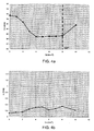
- the value of the heat release rate (HRR) peak drops in a monotonic manner, while the angle of the combustion centroid, shown in Figure 1b and indicated as ⁇ CC , moves in time towards smaller angular values with respect to the reference point constituted by top dead centre TDC.
- the reduction in heat release rate peak results in a drop in the pressure gradient and, in consequence, produces a reduction in combustion noise, shown in Figure 1c and indicated as CN, which drops as Tp-m increases until a minimum is reached, after which the noise starts to increase again, as the pilot combustion becomes the noise source.
- the drop in HRR peak obtainable by increasing the pilot quantity Qp, with a constant combustion centroid, is due to the change in the way in which the heat releases of the fuel quantities, injected in the pilot and main injection respectively, are summed.
- the quantity of fuel injected during the pilot injection is in fact able to burn immediately, before the quantity injected with the main injection, without summing itself to the latter and so generating more gradual heat release.
- the pilot quantity is not utilized for the purpose of varying the ignition delay of the main injection, a characteristic conventionally requested from the pilot injection, because both quantities are premixed before combustion starts, thanks to the low ignitability characteristics of the gas mixture used in premixed combustion, and because the combustion of the pilot quantity, premixed and with a low temperature, is not able to trigger the start of combustion of the main quantity, nor to change the ignition delay in any appreciable manner, and consequently it does not change the total premixing of the quantity of fuel and the associated pollutant emissions. In these conditions, the pilot quantity becomes a tool able to vary and model the combustion heat release, without altering pollutant emissions.
- combustion noise exhibits a reversal and starts to increase. This phenomenon is due to the fact that an increasing quantity of fuel burns at more advanced crank angles, in the presence of smaller chamber volumes, and consequently this starts to become the main source of noise in the combustion event.
- the Applicant has noted that it is preferable to set a limit for combustion noise as a function of engine running conditions, based on the demands for comfort required in the particular application to which the engine is destined, for example, by calibrating a combustion-noise limit map as a function of engine RPM and load.
- the described control system varies the pilot quantity in order to obtain the desired combustion noise value, compensating each change in environmental conditions or conditions due to engine usage, for example, during temporary acceleration or deceleration (situations in which engine conditions are not stationary and, most likely, different from the conditions in which the engine was calibrated on the bench), but without ever exceeding the characteristic limit values, Qpil* and Qpil**, beyond which pollutant emissions and combustion noise increase.
- the above-mentioned limit values Qpil* and Qpil** may change as engine running conditions and environmental conditions change. For example, they could be calibrated in maps or vectors based on engine conditions.
- This operation of primary importance is performed by controlling one of the quantities associated with the combustion position itself, such as MFB50% for example, or the centroid of the subtended HRR curve, and acting on the timing position of the injection sequence (pilot plus main), as is shown in Figure 6 .
- TDC Top Dead Centre
- the system forming the subject of the present invention is able to optimize the operation of a diesel engine with premixed charge compression ignition, within the previously described operating limits, by simultaneously controlling two characteristic quantities of the combustion process:
- Both controls act on the method of injecting fuel.
- Said method of injecting fuel is preferably characterized by a sequence of injections, pilot and main, with one following the other after a preferably fixed time lag Tp-m.
- Tp-m time lag
- Control of combustion noise is achieved by varying the quantity for pilot injection: an increase in the pilot quantity corresponds to a drop in combustion noise.
- Control of the combustion centroid is achieved by varying the position of the injection sequence: an advance or delay in the injection sequence corresponds to an advance or delay in the combustion centroid.
- control system functions via one or more sensors that measure characteristic quantities of the combustion process, from which, by direct measurement or indirect calculation, the following values are obtained:
- a control block for example, a proportional - integral - derivate (PID) control
- Quantity ii) enters control branch "B" is compared with a reference value and, based on the deviation from the desired value, namely the reference value, a control block (for example, a PID control) calculates the position of the injection sequence to be performed at the successive injection of fuel, modifying one of the parameters SOI Pilot or SOI Main.
- a control block for example, a PID control
- the two control branches A and B ( Figure 7 ), the first one assigned to controlling combustion noise, the second to controlling the position of the combustion centroid, contribute to generating the injection event of the next engine cycle.
- the additional parameter that unambiguously defines the injection event namely the quantity Qmain injected by the main injection, is instead calculated starting from the torque requested from the engine, according to any of the known methodologies.
Landscapes
- Engineering & Computer Science (AREA)
- Chemical & Material Sciences (AREA)
- Combustion & Propulsion (AREA)
- Mechanical Engineering (AREA)
- General Engineering & Computer Science (AREA)
- Electrical Control Of Air Or Fuel Supplied To Internal-Combustion Engine (AREA)
Claims (15)
- Système de commande électronique (1) configuré de façon à commander en boucle fermée la combustion de carburant dans un moteur diesel à allumage par compression à charge prémélangée (PCCI) doté d'un système d'injection de carburant commandé de manière électronique (7) configuré de façon à exécuter une séquence d'injection de carburant dans un cylindre moteur (8) par cycle moteur et comprenant au moins une injection de carburant pilote (P) et une injection de carburant principale successive (M) ;
le système de commande électronique (1) comprenant :- des moyens formant détecteur (2) configurés de façon à déterminer des quantités caractéristiques de combustion de carburant comprenant une quantité indicative d'une position de combustion de carburant dans un cycle moteur et une quantité indicative d'un bruit de combustion de carburant ; et- des moyens de commande d'injection de carburant (3, 4a, 5a, 6a, 4b, 5b, 6b) configurés de façon à réguler en boucle fermée la position de la séquence d'injection de carburant dans le cycle moteur et une quantité de carburant pilote (Qp) injectée au cours de l'injection de carburant pilote (P) sur la base des quantités caractéristiques de combustion de carburant ;caractérisé en ce que les moyens de commande d'injection de carburant sont configurés en outre de façon à réguler :- la quantité de carburant pilote (Qp) de façon à commander le bruit de combustion de carburant ; et- la position de la séquence d'injection de carburant dans le cycle moteur de façon à compenser des variations de la position de la combustion de carburant induites par la régulation de la quantité d'essence pilote (Qp) ou dans des conditions environnementales ou de commande de moteur qui provoquent une variation des caractéristiques d'un mélange de gaz d'admission moteur, grâce à quoi le retard d'allumage de l'injection de carburant principale (M) n'est pas affecté par la régulation de la quantité de carburant pilote (Qp). - Système de commande électronique selon la revendication 1, dans lequel la quantité indicative du bruit de combustion de carburant comprend l'une des quantités suivantes :- dérivée de la pression dans le cylindre maximum ;- bruit de combustion de carburant ;- pic maximum du débit calorifique ;
et dans lequel la quantité indicative de la position de la combustion de carburant dans le cycle moteur comprend l'une des quantités suivantes :- angle du vilebrequin moteur pour lequel une fraction de masse donnée (MFB 50 %) du carburant injecté dans un cylindre moteur a brûlé ;- centroïde du débit calorifique (HRR). - Système de commande électronique selon la revendication 1 ou la revendication 2, dans lequel les moyens de commande d'injection de carburant sont configurés en outre de façon à réguler la quantité de carburant pilote (Qp) de manière à ce que le bruit de combustion de carburant prenne des valeurs cibles mappées en fonction de la vitesse et de la charge du moteur.
- Système de commande électronique selon l'une quelconque des revendications précédentes, dans lequel les moyens de commande d'injection de carburant sont configurés en outre de façon à réguler la position de la séquence d'injection de carburant dans le cycle moteur de manière à ce que la position de la combustion de carburant prenne des valeurs cibles mappées en fonction de la vitesse et de la charge du moteur.
- Système de commande électronique selon l'une quelconque des revendications précédentes, dans lequel les moyens de commande d'injection de carburant sont configurés en outre de façon à réguler la position de la séquence d'injection de carburant dans le cycle moteur en régulant la position de l'injection de carburant pilote, tout en maintenant constante la position de l'injection de carburant principale par rapport à la position de l'injection de carburant pilote.
- Système de commande électronique selon l'une quelconque des revendications précédentes, dans lequel les moyens de commande d'injection de carburant sont configurés en outre de façon à réguler la position de la séquence d'injection de carburant dans le cycle moteur en régulant la position de l'injection de carburant principale, tout en maintenant constante la position de l'injection de carburant pilote par rapport à la position de l'injection de carburant principale.
- Système de commande électronique selon la revendication 5 ou la revendication 6, dans lequel le retard (Tp - m) entre les injections de carburant pilote et principale est mappée en fonction de la vitesse et de la charge du moteur.
- Système de commande électronique selon l'une quelconque des revendications précédentes, dans lequel les moyens de commande d'injection de carburant sont configurés en outre de façon à maintenir sensiblement constante la quantité globale de carburant (Qp + Qm) injectée au cours des injections de carburant pilote et principale.
- Système de commande électronique selon l'une quelconque des revendications précédentes, dans lequel les moyens de commande d'injection de carburant sont configurés en outre de façon à réguler en boucle fermée la quantité de carburant pilote (Qp) en exécutant un certain nombre de cycles successifs d'ouverture et de fermeture d'un injecteur de carburant du système d'injection de carburant commandé de manière électronique (7).
- Système de commande électronique selon l'une quelconque des revendications précédentes, dans lequel les moyens de commande d'injection de carburant sont configurés en outre de façon à augmenter la quantité de carburant pilote (Qp) de manière à réduire le bruit de combustion.
- Système de commande électronique selon la revendication 10, dans lequel les moyens de commande d'injection de carburant sont configurés en outre de façon à augmenter la quantité de carburant pilote (Qp) jusqu'à une première valeur limite (Qpil*) au-delà de laquelle une autre augmentation de la quantité de carburant pilote (Qp) produit une augmentation des émissions de fumée.
- Système de commande électronique selon la revendication 11, dans lequel les moyens de commande d'injection de carburant sont configurés en outre de façon à augmenter la quantité de carburant pilote (Qp) jusqu'à une seconde valeur limite (Qpil**) au-delà de laquelle une autre augmentation de la quantité de carburant pilote (Qp) produit une augmentation du bruit de combustion de carburant.
- Système de commande électronique selon l'une quelconque des revendications précédentes, dans lequel une quantité de carburant principale (Qm) injectée au cours de l'injection de carburant principale (M) est fonction de la vitesse et de la charge du moteur.
- Système d'injection de carburant commandé de manière électronique (7) comprenant un système de commande électronique (1) selon l'une quelconque des revendications précédentes.
- Moteur diesel à allumage par compression à charge prémélangée (PCCI) doté d'un système d'injection de carburant commandé de manière électronique (7) selon la revendication 14.
Priority Applications (1)
| Application Number | Priority Date | Filing Date | Title |
|---|---|---|---|
| EP07425842A EP2075442B1 (fr) | 2007-12-31 | 2007-12-31 | Système de contrôle de combustion électronique en boucle fermée pour moteur diesel fonctionnant avec un allumage de compression de charge prémélangée |
Applications Claiming Priority (1)
| Application Number | Priority Date | Filing Date | Title |
|---|---|---|---|
| EP07425842A EP2075442B1 (fr) | 2007-12-31 | 2007-12-31 | Système de contrôle de combustion électronique en boucle fermée pour moteur diesel fonctionnant avec un allumage de compression de charge prémélangée |
Publications (2)
| Publication Number | Publication Date |
|---|---|
| EP2075442A1 EP2075442A1 (fr) | 2009-07-01 |
| EP2075442B1 true EP2075442B1 (fr) | 2012-09-05 |
Family
ID=39469565
Family Applications (1)
| Application Number | Title | Priority Date | Filing Date |
|---|---|---|---|
| EP07425842A Not-in-force EP2075442B1 (fr) | 2007-12-31 | 2007-12-31 | Système de contrôle de combustion électronique en boucle fermée pour moteur diesel fonctionnant avec un allumage de compression de charge prémélangée |
Country Status (1)
| Country | Link |
|---|---|
| EP (1) | EP2075442B1 (fr) |
Families Citing this family (11)
| Publication number | Priority date | Publication date | Assignee | Title |
|---|---|---|---|---|
| AT503739B1 (de) * | 2007-09-13 | 2009-07-15 | Avl List Gmbh | Verfahren zur regelung der verbrennungslage bei einer brennkraftmaschine |
| JP2011220186A (ja) * | 2010-04-08 | 2011-11-04 | Toyota Motor Corp | 内燃機関の燃焼制御装置 |
| DE102011055275B4 (de) * | 2011-11-11 | 2024-12-05 | FEV Europe GmbH | Verfahren zur Regelung der Abgastemperatur einer direkteinspritzenden Brennkraftmaschine |
| DE102012004585A1 (de) * | 2012-03-09 | 2013-09-12 | Man Truck & Bus Ag | Schallabstrahlreduziertes Kraftfahrzeug |
| JP2015113790A (ja) * | 2013-12-12 | 2015-06-22 | トヨタ自動車株式会社 | 内燃機関の制御装置 |
| JP6332071B2 (ja) | 2015-02-12 | 2018-05-30 | 株式会社デンソー | 燃料噴射制御装置 |
| IT201700033222A1 (it) * | 2017-03-27 | 2018-09-27 | Magneti Marelli Spa | Metodo per controllare un motore a combustione interna ad accensione spontanea |
| JP7163671B2 (ja) * | 2018-08-29 | 2022-11-01 | トヨタ自動車株式会社 | 内燃機関の制御装置 |
| CN111259544B (zh) * | 2020-01-15 | 2024-01-26 | 重庆大学 | 固体火箭发动机烤燃过程中热点形成时间的获得方法 |
| CN113074050A (zh) * | 2021-04-08 | 2021-07-06 | 安徽砺德特种动力科技有限公司 | 一种电喷发动机、无人机用发动机 |
| CN116118686B (zh) * | 2022-12-23 | 2024-07-30 | 吉林大学 | 一种基于集成式电液制动系统的汽车制动滑移率控制方法 |
Family Cites Families (11)
| Publication number | Priority date | Publication date | Assignee | Title |
|---|---|---|---|---|
| JP3092552B2 (ja) | 1997-09-16 | 2000-09-25 | トヨタ自動車株式会社 | 圧縮着火式内燃機関 |
| JP3622446B2 (ja) | 1997-09-30 | 2005-02-23 | 日産自動車株式会社 | ディーゼルエンジンの燃焼制御装置 |
| JP3421059B2 (ja) * | 1998-02-23 | 2003-06-30 | カミンス エンジン カンパニー インコーポレイテッド | 最適燃焼コントロールを有する予混合チャージ圧縮点火エンジン |
| WO2001086128A2 (fr) | 2000-05-08 | 2001-11-15 | Cummins, Inc. | Moteur a combustion interne fonctionnant en mode d'allumage par compression de charge premelangee avec injection de commande precoce, et son procede de fonctionnement |
| AT5217U1 (de) | 2001-09-28 | 2002-04-25 | Avl List Gmbh | Verfahren zum geregelten betrieb einer brennkraftmaschine |
| US6964256B2 (en) | 2002-03-28 | 2005-11-15 | Mazda Motor Corporation | Combustion control apparatus for an engine |
| JP4075588B2 (ja) * | 2002-11-26 | 2008-04-16 | いすゞ自動車株式会社 | ディーゼルエンジン |
| DE10344423A1 (de) * | 2003-09-25 | 2005-04-21 | Daimler Chrysler Ag | Verfahren zum Betrieb einer Brennkraftmaschine |
| DE10344427B4 (de) * | 2003-09-25 | 2015-02-19 | Daimler Ag | Verfahren zum Betrieb einer Brennkraftmaschine |
| DE602004020197D1 (de) | 2004-06-15 | 2009-05-07 | Fiat Ricerche | Regelungssystem zur Regelung der Verbrennung in einem Dieselmotor mit vorgemischter Verbrennung |
| DE102005058820B4 (de) * | 2005-12-09 | 2016-11-17 | Daimler Ag | Verfahren zur Regelung einer Brennkraftmaschine, insbesondere einer selbstzündenden Brennkraftmaschine |
-
2007
- 2007-12-31 EP EP07425842A patent/EP2075442B1/fr not_active Not-in-force
Also Published As
| Publication number | Publication date |
|---|---|
| EP2075442A1 (fr) | 2009-07-01 |
Similar Documents
| Publication | Publication Date | Title |
|---|---|---|
| EP2075442A1 (fr) | Système de contrôle de combustion électronique en boucle fermée pour moteur diesel fonctionnant avec un allumage de compression de charge prémélangée | |
| CN101915175B (zh) | 调整喷射和火花正时扩展hcci运转高负载极限的方法 | |
| EP1607609B1 (fr) | Système de régulation pour contrôler la combustion dans un moteur diesel fonctionnant avec combustion prémélangée | |
| CN102235257B (zh) | 多次喷射正时控制的方法 | |
| US7845335B2 (en) | Operating strategy for HCCI combustion during engine warm-up | |
| CN101946074B (zh) | 用于在低负载下控制火花点火直接喷射式内燃机的方法 | |
| EP2058499B1 (fr) | Appareil et procédé de contrôle d'un moteur à combustion interne à allumage par compression de charge homogène | |
| US9803580B2 (en) | Method and apparatus for controlling operation of an internal combustion engine | |
| US7475671B1 (en) | Method for compensating injection timing during transient response of pre-mixed combustion | |
| US7412322B1 (en) | Method and apparatus for engine control during auto-ignition combustion | |
| CN101655044B (zh) | 使用气缸压力差的发动机控制 | |
| CN108301933B (zh) | 内燃机的控制装置 | |
| CN101907029B (zh) | 用于调节小燃料喷射量的方法和系统 | |
| CN102261286B (zh) | 控制以hcci燃烧模式操作的内燃机的操作的方法和设备 | |
| JP2007507641A (ja) | 気体燃料式内燃機関におけるパイロット燃料の導入と燃焼制御の方法および手段 | |
| CN105822443B (zh) | 用于控制以hcci燃烧模式操作的内燃机的操作的方法和设备 | |
| CN102084108A (zh) | 通过燃料压力变化的轻负载和怠速hcci燃烧控制的改善 | |
| KR20210141753A (ko) | 내연 기관에서의 자동 점화 제어 | |
| US11220971B2 (en) | Control apparatus for compression-ignition type engine | |
| CN104632441B (zh) | 以hcci燃烧模式运行的内燃机的运行控制方法和设备 | |
| US8645044B2 (en) | Method and apparatus for operating an internal combustion engine in a homogeneous-charge compression-ignition combustion mode | |
| EP3421765B1 (fr) | Moteur à autoallumage par compression | |
| US11313269B2 (en) | Control apparatus for compression-ignition type engine | |
| CN102128096B (zh) | 多脉冲喷射燃料和负载平衡控制系统 | |
| US11105255B2 (en) | Control apparatus for compression-ignition type engine |
Legal Events
| Date | Code | Title | Description |
|---|---|---|---|
| PUAI | Public reference made under article 153(3) epc to a published international application that has entered the european phase |
Free format text: ORIGINAL CODE: 0009012 |
|
| AK | Designated contracting states |
Kind code of ref document: A1 Designated state(s): AT BE BG CH CY CZ DE DK EE ES FI FR GB GR HU IE IS IT LI LT LU LV MC MT NL PL PT RO SE SI SK TR |
|
| AX | Request for extension of the european patent |
Extension state: AL BA HR MK RS |
|
| 17P | Request for examination filed |
Effective date: 20100104 |
|
| AKX | Designation fees paid |
Designated state(s): AT BE BG CH CY CZ DE DK EE ES FI FR GB GR HU IE IS IT LI LT LU LV MC MT NL PL PT RO SE SI SK TR |
|
| GRAP | Despatch of communication of intention to grant a patent |
Free format text: ORIGINAL CODE: EPIDOSNIGR1 |
|
| GRAS | Grant fee paid |
Free format text: ORIGINAL CODE: EPIDOSNIGR3 |
|
| GRAA | (expected) grant |
Free format text: ORIGINAL CODE: 0009210 |
|
| AK | Designated contracting states |
Kind code of ref document: B1 Designated state(s): AT BE BG CH CY CZ DE DK EE ES FI FR GB GR HU IE IS IT LI LT LU LV MC MT NL PL PT RO SE SI SK TR |
|
| REG | Reference to a national code |
Ref country code: GB Ref legal event code: FG4D |
|
| REG | Reference to a national code |
Ref country code: CH Ref legal event code: EP |
|
| REG | Reference to a national code |
Ref country code: AT Ref legal event code: REF Ref document number: 574248 Country of ref document: AT Kind code of ref document: T Effective date: 20120915 |
|
| REG | Reference to a national code |
Ref country code: IE Ref legal event code: FG4D |
|
| REG | Reference to a national code |
Ref country code: DE Ref legal event code: R096 Ref document number: 602007025266 Country of ref document: DE Effective date: 20121031 |
|
| REG | Reference to a national code |
Ref country code: AT Ref legal event code: MK05 Ref document number: 574248 Country of ref document: AT Kind code of ref document: T Effective date: 20120905 |
|
| REG | Reference to a national code |
Ref country code: NL Ref legal event code: VDEP Effective date: 20120905 |
|
| PG25 | Lapsed in a contracting state [announced via postgrant information from national office to epo] |
Ref country code: AT Free format text: LAPSE BECAUSE OF FAILURE TO SUBMIT A TRANSLATION OF THE DESCRIPTION OR TO PAY THE FEE WITHIN THE PRESCRIBED TIME-LIMIT Effective date: 20120905 Ref country code: LT Free format text: LAPSE BECAUSE OF FAILURE TO SUBMIT A TRANSLATION OF THE DESCRIPTION OR TO PAY THE FEE WITHIN THE PRESCRIBED TIME-LIMIT Effective date: 20120905 Ref country code: CY Free format text: LAPSE BECAUSE OF FAILURE TO SUBMIT A TRANSLATION OF THE DESCRIPTION OR TO PAY THE FEE WITHIN THE PRESCRIBED TIME-LIMIT Effective date: 20120905 Ref country code: FI Free format text: LAPSE BECAUSE OF FAILURE TO SUBMIT A TRANSLATION OF THE DESCRIPTION OR TO PAY THE FEE WITHIN THE PRESCRIBED TIME-LIMIT Effective date: 20120905 |
|
| REG | Reference to a national code |
Ref country code: LT Ref legal event code: MG4D Effective date: 20120905 |
|
| PG25 | Lapsed in a contracting state [announced via postgrant information from national office to epo] |
Ref country code: SI Free format text: LAPSE BECAUSE OF FAILURE TO SUBMIT A TRANSLATION OF THE DESCRIPTION OR TO PAY THE FEE WITHIN THE PRESCRIBED TIME-LIMIT Effective date: 20120905 Ref country code: LV Free format text: LAPSE BECAUSE OF FAILURE TO SUBMIT A TRANSLATION OF THE DESCRIPTION OR TO PAY THE FEE WITHIN THE PRESCRIBED TIME-LIMIT Effective date: 20120905 Ref country code: SE Free format text: LAPSE BECAUSE OF FAILURE TO SUBMIT A TRANSLATION OF THE DESCRIPTION OR TO PAY THE FEE WITHIN THE PRESCRIBED TIME-LIMIT Effective date: 20120905 Ref country code: GR Free format text: LAPSE BECAUSE OF FAILURE TO SUBMIT A TRANSLATION OF THE DESCRIPTION OR TO PAY THE FEE WITHIN THE PRESCRIBED TIME-LIMIT Effective date: 20121206 |
|
| PG25 | Lapsed in a contracting state [announced via postgrant information from national office to epo] |
Ref country code: BE Free format text: LAPSE BECAUSE OF FAILURE TO SUBMIT A TRANSLATION OF THE DESCRIPTION OR TO PAY THE FEE WITHIN THE PRESCRIBED TIME-LIMIT Effective date: 20120905 Ref country code: IS Free format text: LAPSE BECAUSE OF FAILURE TO SUBMIT A TRANSLATION OF THE DESCRIPTION OR TO PAY THE FEE WITHIN THE PRESCRIBED TIME-LIMIT Effective date: 20130105 Ref country code: EE Free format text: LAPSE BECAUSE OF FAILURE TO SUBMIT A TRANSLATION OF THE DESCRIPTION OR TO PAY THE FEE WITHIN THE PRESCRIBED TIME-LIMIT Effective date: 20120905 Ref country code: RO Free format text: LAPSE BECAUSE OF FAILURE TO SUBMIT A TRANSLATION OF THE DESCRIPTION OR TO PAY THE FEE WITHIN THE PRESCRIBED TIME-LIMIT Effective date: 20120905 Ref country code: NL Free format text: LAPSE BECAUSE OF FAILURE TO SUBMIT A TRANSLATION OF THE DESCRIPTION OR TO PAY THE FEE WITHIN THE PRESCRIBED TIME-LIMIT Effective date: 20120905 Ref country code: CZ Free format text: LAPSE BECAUSE OF FAILURE TO SUBMIT A TRANSLATION OF THE DESCRIPTION OR TO PAY THE FEE WITHIN THE PRESCRIBED TIME-LIMIT Effective date: 20120905 Ref country code: ES Free format text: LAPSE BECAUSE OF FAILURE TO SUBMIT A TRANSLATION OF THE DESCRIPTION OR TO PAY THE FEE WITHIN THE PRESCRIBED TIME-LIMIT Effective date: 20121216 |
|
| PG25 | Lapsed in a contracting state [announced via postgrant information from national office to epo] |
Ref country code: PL Free format text: LAPSE BECAUSE OF FAILURE TO SUBMIT A TRANSLATION OF THE DESCRIPTION OR TO PAY THE FEE WITHIN THE PRESCRIBED TIME-LIMIT Effective date: 20120905 Ref country code: PT Free format text: LAPSE BECAUSE OF FAILURE TO SUBMIT A TRANSLATION OF THE DESCRIPTION OR TO PAY THE FEE WITHIN THE PRESCRIBED TIME-LIMIT Effective date: 20130107 Ref country code: SK Free format text: LAPSE BECAUSE OF FAILURE TO SUBMIT A TRANSLATION OF THE DESCRIPTION OR TO PAY THE FEE WITHIN THE PRESCRIBED TIME-LIMIT Effective date: 20120905 |
|
| PLBE | No opposition filed within time limit |
Free format text: ORIGINAL CODE: 0009261 |
|
| STAA | Information on the status of an ep patent application or granted ep patent |
Free format text: STATUS: NO OPPOSITION FILED WITHIN TIME LIMIT |
|
| PG25 | Lapsed in a contracting state [announced via postgrant information from national office to epo] |
Ref country code: BG Free format text: LAPSE BECAUSE OF FAILURE TO SUBMIT A TRANSLATION OF THE DESCRIPTION OR TO PAY THE FEE WITHIN THE PRESCRIBED TIME-LIMIT Effective date: 20121205 Ref country code: MC Free format text: LAPSE BECAUSE OF NON-PAYMENT OF DUE FEES Effective date: 20121231 Ref country code: DK Free format text: LAPSE BECAUSE OF FAILURE TO SUBMIT A TRANSLATION OF THE DESCRIPTION OR TO PAY THE FEE WITHIN THE PRESCRIBED TIME-LIMIT Effective date: 20120905 |
|
| REG | Reference to a national code |
Ref country code: CH Ref legal event code: PL |
|
| 26N | No opposition filed |
Effective date: 20130606 |
|
| GBPC | Gb: european patent ceased through non-payment of renewal fee |
Effective date: 20121231 |
|
| REG | Reference to a national code |
Ref country code: IE Ref legal event code: MM4A |
|
| REG | Reference to a national code |
Ref country code: DE Ref legal event code: R097 Ref document number: 602007025266 Country of ref document: DE Effective date: 20130606 |
|
| PG25 | Lapsed in a contracting state [announced via postgrant information from national office to epo] |
Ref country code: CH Free format text: LAPSE BECAUSE OF NON-PAYMENT OF DUE FEES Effective date: 20121231 Ref country code: LI Free format text: LAPSE BECAUSE OF NON-PAYMENT OF DUE FEES Effective date: 20121231 Ref country code: IE Free format text: LAPSE BECAUSE OF NON-PAYMENT OF DUE FEES Effective date: 20121231 |
|
| PG25 | Lapsed in a contracting state [announced via postgrant information from national office to epo] |
Ref country code: GB Free format text: LAPSE BECAUSE OF NON-PAYMENT OF DUE FEES Effective date: 20121231 Ref country code: MT Free format text: LAPSE BECAUSE OF FAILURE TO SUBMIT A TRANSLATION OF THE DESCRIPTION OR TO PAY THE FEE WITHIN THE PRESCRIBED TIME-LIMIT Effective date: 20120905 |
|
| PG25 | Lapsed in a contracting state [announced via postgrant information from national office to epo] |
Ref country code: TR Free format text: LAPSE BECAUSE OF FAILURE TO SUBMIT A TRANSLATION OF THE DESCRIPTION OR TO PAY THE FEE WITHIN THE PRESCRIBED TIME-LIMIT Effective date: 20120905 |
|
| PG25 | Lapsed in a contracting state [announced via postgrant information from national office to epo] |
Ref country code: LU Free format text: LAPSE BECAUSE OF NON-PAYMENT OF DUE FEES Effective date: 20121231 |
|
| PG25 | Lapsed in a contracting state [announced via postgrant information from national office to epo] |
Ref country code: HU Free format text: LAPSE BECAUSE OF FAILURE TO SUBMIT A TRANSLATION OF THE DESCRIPTION OR TO PAY THE FEE WITHIN THE PRESCRIBED TIME-LIMIT Effective date: 20071231 |
|
| REG | Reference to a national code |
Ref country code: FR Ref legal event code: PLFP Year of fee payment: 9 |
|
| REG | Reference to a national code |
Ref country code: FR Ref legal event code: PLFP Year of fee payment: 10 |
|
| REG | Reference to a national code |
Ref country code: FR Ref legal event code: PLFP Year of fee payment: 11 |
|
| PGFP | Annual fee paid to national office [announced via postgrant information from national office to epo] |
Ref country code: FR Payment date: 20171226 Year of fee payment: 11 |
|
| PGFP | Annual fee paid to national office [announced via postgrant information from national office to epo] |
Ref country code: IT Payment date: 20171212 Year of fee payment: 11 |
|
| PGFP | Annual fee paid to national office [announced via postgrant information from national office to epo] |
Ref country code: DE Payment date: 20180228 Year of fee payment: 11 |
|
| REG | Reference to a national code |
Ref country code: DE Ref legal event code: R119 Ref document number: 602007025266 Country of ref document: DE |
|
| PG25 | Lapsed in a contracting state [announced via postgrant information from national office to epo] |
Ref country code: IT Free format text: LAPSE BECAUSE OF NON-PAYMENT OF DUE FEES Effective date: 20181231 Ref country code: FR Free format text: LAPSE BECAUSE OF NON-PAYMENT OF DUE FEES Effective date: 20181231 Ref country code: DE Free format text: LAPSE BECAUSE OF NON-PAYMENT OF DUE FEES Effective date: 20190702 |