EP2075462B1 - Windkraftanlage, Steuerungssystem und Steuerverfahren für Windturbinen - Google Patents
Windkraftanlage, Steuerungssystem und Steuerverfahren für Windturbinen Download PDFInfo
- Publication number
- EP2075462B1 EP2075462B1 EP08171280.4A EP08171280A EP2075462B1 EP 2075462 B1 EP2075462 B1 EP 2075462B1 EP 08171280 A EP08171280 A EP 08171280A EP 2075462 B1 EP2075462 B1 EP 2075462B1
- Authority
- EP
- European Patent Office
- Prior art keywords
- rotor blade
- wind turbine
- rotor
- sensor
- stall
- Prior art date
- Legal status (The legal status is an assumption and is not a legal conclusion. Google has not performed a legal analysis and makes no representation as to the accuracy of the status listed.)
- Active
Links
Images


Classifications
-
- F—MECHANICAL ENGINEERING; LIGHTING; HEATING; WEAPONS; BLASTING
- F03—MACHINES OR ENGINES FOR LIQUIDS; WIND, SPRING, OR WEIGHT MOTORS; PRODUCING MECHANICAL POWER OR A REACTIVE PROPULSIVE THRUST, NOT OTHERWISE PROVIDED FOR
- F03D—WIND MOTORS
- F03D7/00—Controlling wind motors
- F03D7/02—Controlling wind motors the wind motors having rotation axis substantially parallel to the air flow entering the rotor
- F03D7/022—Adjusting aerodynamic properties of the blades
- F03D7/024—Adjusting aerodynamic properties of the blades of individual blades
-
- F—MECHANICAL ENGINEERING; LIGHTING; HEATING; WEAPONS; BLASTING
- F03—MACHINES OR ENGINES FOR LIQUIDS; WIND, SPRING, OR WEIGHT MOTORS; PRODUCING MECHANICAL POWER OR A REACTIVE PROPULSIVE THRUST, NOT OTHERWISE PROVIDED FOR
- F03D—WIND MOTORS
- F03D7/00—Controlling wind motors
- F03D7/02—Controlling wind motors the wind motors having rotation axis substantially parallel to the air flow entering the rotor
- F03D7/022—Adjusting aerodynamic properties of the blades
- F03D7/0224—Adjusting blade pitch
-
- F—MECHANICAL ENGINEERING; LIGHTING; HEATING; WEAPONS; BLASTING
- F03—MACHINES OR ENGINES FOR LIQUIDS; WIND, SPRING, OR WEIGHT MOTORS; PRODUCING MECHANICAL POWER OR A REACTIVE PROPULSIVE THRUST, NOT OTHERWISE PROVIDED FOR
- F03D—WIND MOTORS
- F03D7/00—Controlling wind motors
- F03D7/02—Controlling wind motors the wind motors having rotation axis substantially parallel to the air flow entering the rotor
- F03D7/0256—Stall control
-
- F—MECHANICAL ENGINEERING; LIGHTING; HEATING; WEAPONS; BLASTING
- F03—MACHINES OR ENGINES FOR LIQUIDS; WIND, SPRING, OR WEIGHT MOTORS; PRODUCING MECHANICAL POWER OR A REACTIVE PROPULSIVE THRUST, NOT OTHERWISE PROVIDED FOR
- F03D—WIND MOTORS
- F03D7/00—Controlling wind motors
- F03D7/02—Controlling wind motors the wind motors having rotation axis substantially parallel to the air flow entering the rotor
- F03D7/0296—Controlling wind motors the wind motors having rotation axis substantially parallel to the air flow entering the rotor to prevent, counteract or reduce noise emissions
-
- F—MECHANICAL ENGINEERING; LIGHTING; HEATING; WEAPONS; BLASTING
- F03—MACHINES OR ENGINES FOR LIQUIDS; WIND, SPRING, OR WEIGHT MOTORS; PRODUCING MECHANICAL POWER OR A REACTIVE PROPULSIVE THRUST, NOT OTHERWISE PROVIDED FOR
- F03D—WIND MOTORS
- F03D7/00—Controlling wind motors
- F03D7/02—Controlling wind motors the wind motors having rotation axis substantially parallel to the air flow entering the rotor
- F03D7/04—Automatic control; Regulation
- F03D7/042—Automatic control; Regulation by means of an electrical or electronic controller
-
- F—MECHANICAL ENGINEERING; LIGHTING; HEATING; WEAPONS; BLASTING
- F05—INDEXING SCHEMES RELATING TO ENGINES OR PUMPS IN VARIOUS SUBCLASSES OF CLASSES F01-F04
- F05B—INDEXING SCHEME RELATING TO WIND, SPRING, WEIGHT, INERTIA OR LIKE MOTORS, TO MACHINES OR ENGINES FOR LIQUIDS COVERED BY SUBCLASSES F03B, F03D AND F03G
- F05B2260/00—Function
- F05B2260/96—Preventing, counteracting or reducing vibration or noise
-
- F—MECHANICAL ENGINEERING; LIGHTING; HEATING; WEAPONS; BLASTING
- F05—INDEXING SCHEMES RELATING TO ENGINES OR PUMPS IN VARIOUS SUBCLASSES OF CLASSES F01-F04
- F05B—INDEXING SCHEME RELATING TO WIND, SPRING, WEIGHT, INERTIA OR LIKE MOTORS, TO MACHINES OR ENGINES FOR LIQUIDS COVERED BY SUBCLASSES F03B, F03D AND F03G
- F05B2270/00—Control
- F05B2270/30—Control parameters, e.g. input parameters
- F05B2270/326—Rotor angle
-
- F—MECHANICAL ENGINEERING; LIGHTING; HEATING; WEAPONS; BLASTING
- F05—INDEXING SCHEMES RELATING TO ENGINES OR PUMPS IN VARIOUS SUBCLASSES OF CLASSES F01-F04
- F05B—INDEXING SCHEME RELATING TO WIND, SPRING, WEIGHT, INERTIA OR LIKE MOTORS, TO MACHINES OR ENGINES FOR LIQUIDS COVERED BY SUBCLASSES F03B, F03D AND F03G
- F05B2270/00—Control
- F05B2270/30—Control parameters, e.g. input parameters
- F05B2270/328—Blade pitch angle
-
- F—MECHANICAL ENGINEERING; LIGHTING; HEATING; WEAPONS; BLASTING
- F05—INDEXING SCHEMES RELATING TO ENGINES OR PUMPS IN VARIOUS SUBCLASSES OF CLASSES F01-F04
- F05B—INDEXING SCHEME RELATING TO WIND, SPRING, WEIGHT, INERTIA OR LIKE MOTORS, TO MACHINES OR ENGINES FOR LIQUIDS COVERED BY SUBCLASSES F03B, F03D AND F03G
- F05B2270/00—Control
- F05B2270/30—Control parameters, e.g. input parameters
- F05B2270/333—Noise or sound levels
-
- F—MECHANICAL ENGINEERING; LIGHTING; HEATING; WEAPONS; BLASTING
- F05—INDEXING SCHEMES RELATING TO ENGINES OR PUMPS IN VARIOUS SUBCLASSES OF CLASSES F01-F04
- F05B—INDEXING SCHEME RELATING TO WIND, SPRING, WEIGHT, INERTIA OR LIKE MOTORS, TO MACHINES OR ENGINES FOR LIQUIDS COVERED BY SUBCLASSES F03B, F03D AND F03G
- F05B2270/00—Control
- F05B2270/30—Control parameters, e.g. input parameters
- F05B2270/334—Vibration measurements
-
- F—MECHANICAL ENGINEERING; LIGHTING; HEATING; WEAPONS; BLASTING
- F05—INDEXING SCHEMES RELATING TO ENGINES OR PUMPS IN VARIOUS SUBCLASSES OF CLASSES F01-F04
- F05B—INDEXING SCHEME RELATING TO WIND, SPRING, WEIGHT, INERTIA OR LIKE MOTORS, TO MACHINES OR ENGINES FOR LIQUIDS COVERED BY SUBCLASSES F03B, F03D AND F03G
- F05B2270/00—Control
- F05B2270/30—Control parameters, e.g. input parameters
- F05B2270/336—Blade lift measurements
-
- Y—GENERAL TAGGING OF NEW TECHNOLOGICAL DEVELOPMENTS; GENERAL TAGGING OF CROSS-SECTIONAL TECHNOLOGIES SPANNING OVER SEVERAL SECTIONS OF THE IPC; TECHNICAL SUBJECTS COVERED BY FORMER USPC CROSS-REFERENCE ART COLLECTIONS [XRACs] AND DIGESTS
- Y02—TECHNOLOGIES OR APPLICATIONS FOR MITIGATION OR ADAPTATION AGAINST CLIMATE CHANGE
- Y02E—REDUCTION OF GREENHOUSE GAS [GHG] EMISSIONS, RELATED TO ENERGY GENERATION, TRANSMISSION OR DISTRIBUTION
- Y02E10/00—Energy generation through renewable energy sources
- Y02E10/70—Wind energy
- Y02E10/72—Wind turbines with rotation axis in wind direction
Definitions
- a wind turbine, a wind turbine controller, and a method for controlling a wind turbine are disclosed herein.
- the wind turbine, the wind turbine controller, and the method for controlling the wind turbine described herein are adapted to take rotor blade stall into account.
- wind turbines capture kinetic energy from wind and convert it into rotational energy of a rotor shaft.
- this rotational energy is used to drive an electric generator, either directly or via a gear box.
- the amount of power extracted from the wind depends, inter alia, on the aerodynamic angle of attack between the rotor blade nose and the incoming air flow. If, for a given wind speed, a certain maximum angle of attack is exceeded, the flow separates at the rotor blades' surface and vortices form at the blade. This effect is known as stall and limits the aerodynamic power capture. Furthermore, stall may increase the noise generated by the wind turbine which might be a problem, e.g. when the turbine site is located near residential areas and particularly during nighttimes.
- JP 2004 293527 describes a wind turbine that is controlled to reduce noise emissions therefrom.
- the wind turbine includes a noise measuring device located on the wind turbine tower (8) or remotely therefrom (9).
- EP 2 131 037 describes a wind turbine sound spectrum analysis system that monitors tower-based sound sensors (16, 17).
- WO 2006/090215 describes a high-lift/low solidity wind turbine blade.
- DE 10 2006 028167 A1 discloses a method of operating a device, which has at least one fluid-dynamic buoyancy body, such as a wind turbine with rotor blades.
- Fig. 1 shows a front view of a wind turbine 10 according to an embodiment.
- the wind turbine 10 includes a tower 2 on top of which a nacelle 6 is mounted.
- a wind rotor 4 equipped with three rotor blades 8a, 8b, 8c is rotatably mounted to nacelle 6. It will be understood by those skilled in the art that the embodiments of the present invention may also be applied to wind turbines having one, two, or more than three rotor blades.
- Rotor blades 8a, 8b, 8c capture kinetic energy from the wind and urge rotor 4 to rotate about its rotation axis. While rotating, rotor blades 8a, 8b, 8c define a circular disc 9.
- the rotational position of a rotor blade on this disc can be described by an angle ⁇ .
- the angle a may be defined as the angle between the longitudinal axis of the rotor blade and the vertical tower axis as shown in Fig. 1 . Although this is the most straightforward definition of the rotational position, also other definitions may be applied in the embodiments of the present invention as long as the rotational position of the rotor blade(s) can be uniquely determined.
- the wind turbine 10 includes sensors 80a, 80b, 80c disposed at the rotor blades 8a, 8b, 8c, respectively.
- each rotor blade 8a, 8b, 8c is equipped with a respective sensor 80a, 80b, 80c in the embodiment shown in Fig. 1 , it will be understood by those skilled in the art that in some embodiments of the present invention only one or two rotor blades will be equipped with sensors.
- only one sensor 80a, 80b, 80c is shown per rotor blade in Fig. 1 but it will be understood by those skilled in the art that two or more sensors per rotor blade may be applied in embodiments according to the present invention.
- Each sensor 80a, 80b, 80c is adapted to detect an aerodynamic condition of the rotor blade.
- the aerodynamic condition detected by a sensor 80a, 80b, 80c is a stall condition of the rotor blade to which the sensor is associated.
- other aerodynamic conditions may be detected by the sensors 80a, 80b, 80c, for example deterioration of the aerodynamical performance of the rotor blade due to icing, increased surface roughness or fouling.
- the senor 80a, 80b, 80c is an acoustical sensor, e.g. a microphone.
- the microphone is adapted to capture the noise generated by the rotating blade.
- the microphone may be integrated in the respective rotor blade at one or more locations along the longitudinal extension of the blade at a position allowing the detection of noise emission generated by the rotating rotor blade.
- the sensor is a vibration sensor adapted to detect a vibrational condition of the rotor blade. Like the microphone, also the vibration sensor may be integrated into the rotor blade.
- a combination of microphones and vibration sensors or even other sensors may be provided to detect the aerodynamical condition of the monitored rotor blade.
- aerodynamical conditions result in a change of the noise generated by the rotor blade or a change in the vibration behavior of the blade
- such aerodynamical conditions may be detected by monitoring the noise generation and/or vibrational state of the rotor blade.
- a blade stall may be detected due to a considerable increase in noise emission and/or due to an increase and/or change in the vibrational condition of the rotor blade.
- the above described sensors provide sensor data allowing to detect such an undesired aerodynamical condition. Furthermore, this allows counteracting the undesired aerodynamical condition when it is detected, e.g. by controlling the pitch angle of the rotor blades.
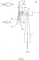
- Fig. 2 shows a side view of a wind turbine 10 according to an embodiment.
- the wind turbine shown in Fig. 2 includes a pitch control system 82 which is adapted to control the pitch angle of the rotor blades and, thus, the rotor blades' angle of attack.
- pitch control system 82 is adapted for individual control of each rotor blade 8a, 8b, 8c.
- pitch control system 82 may adjust the pitch angle of each rotor blade 8a, 8b, 8c differently depending on the individual conditions of the respective rotor blade.
- the sensors 80a, 80b, 80c are connected to pitch control system 82.
- sensors 80a, 80b, 80c are adapted to provide a sensor signal indicative of the detected noise and/or vibration of a respective rotor blade 8a, 8b, 8c to pitch control system 82.
- pitch control system 82 for all rotor blades 8a, 8b, 8c is shown in Fig. 2 , it will be understood by those skilled in the art that a separate pitch control (not shown) may be individually provided for each rotor blade 8a, 8b, 8c.
- each of the several pitch controls may be only connected to the sensor(s) of the rotor blade it controls.
- each separate pitch control may also have input from sensors of other rotor blades so that, e.g. aerodynamical conditions of a trailing rotor blade can be anticipated from sensor data of a leading blade.
- pitch control system 82 is adapted to control the pitch angle of a rotor blade in case a stall condition of the rotor blade is detected on the basis of the sensor input.
- a balde stall occurs if the angle of attack is too large so that the air flow separates at the blade's surface.
- pitch control system 82 adjusts the pitch angle of the stalled blade such that the angle of attack is reduced.
- the blade stall is reduced or even neutralized.
- the cooperation of the sensors and the pitch control system according to embodiments can increase turbine efficiency because losses due to stalled rotor blades are reduced or even completely avoided.
- noise emission due to stalled rotor blades can be considerably reduced or even completely avoided by embodiments of the present invention.
- rotor hub 4 is connected to a rotor shaft 62 which, in turn, is connected to an electric generator 64 either directly or via a gear box (not shown).
- a rotation sensor 66 is mounted, wherein rotation sensor 66 is adapted to detect a rotational position of the rotor hub 4.
- rotation sensor 66 mounted at rotor shaft 62 is only an exemplary embodiment of a rotation sensor capable of detecting the rotational position of hub 4. Accordingly, any other rotation sensor capable of detecting the rotational position of hub 4 may be likewise applied in embodiments of the present invention. As is shown in Fig.
- pitch control system 82 is further adapted to receive an input from rotation sensor 66.
- pitch control system 82 not only considers the noise data and/or vibration data provided by sensors 80a, 80b, 80c but also the rotational position of hub 4.
- pitch control system 82 may determine the rotational position of each rotor blade 8a, 8b, 8c from the data provided by rotation sensor 66.
- pitch control system 82 may also take into account the rotational position ⁇ of each rotor blade when controlling the pitch angle for this rotor blade. Knowledge of the rotational position ⁇ of the rotor blade may improve stall monitoring and control for this rotor blade for the following reason.
- the blade pitch angle depends on the rotational speed of the wind rotor, and the rotational speed of the wind rotor depends on the incoming wind speed experienced by the wind rotor. Particularly, the rotational speed of the wind rotor depends on the incoming wind speed with the disc 9 defining the area covered by the rotating blades 8a, 8b, 8c.
- wind speed is not constant across the disc 9. In particular, wind speed is higher in the upper area of disc 9 compared to the lower area of disc 9. In other words, wind speed is lower near to the ground compared with wind speed more distant from the ground, e.g. above nacelle 6. This variation in wind speed is indicated in Fig. 2 by the different size of the two arrows representing the incoming air flow.
- pitch control system 82 As the rotational position of the hub, and thus also of each individual rotor blade, is used to control the pitch angle of the rotor blades 8a, 8b, 8c wind speed variation can be taken into account by pitch control system 82.
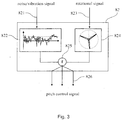
- Fig. 3 shows a schematic diagram of pitch control system 82 according to an embodiment.
- pitch control system 82 includes a first input terminal 821 adapted to receive an input from at least one sensor 80a, 80b, 80c disposed at or near a rotor blade of the wind turbine.
- This sensor is adapted to detect an aerodynamic condition of the rotor blade as has been described above.
- the sensor may be a microphone providing noise data to pitch control system 82.
- the sensor may be a vibration sensor providing vibration data to pitch control system 82.
- Pitch control system 82 includes a noise/vibration analyzing unit 822 to which the sensor data is provided.
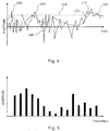
- a noise signal 100 detected by one of the sensors 80a, 80b, 80c is shown.
- the signal 100 indicates the variation of the noise amplitude with time. Higher values of the signal correspond to higher amplitudes of the noise generated by the rotating rotor blade.
- a threshold value 110 is shown as a dashed line in Fig. 4 .
- a threshold value 110 may be empirically determined which, if exceeded, indicates occurrence of a blade stall or another undesirable aerodynamical condition. As is shown in Fig.
- the noise amplitude 100 exhibits several peak values 105 exceeding threshold 110. Therefore, a blade stall may be detected by comparing the actual amplitude value 100 with the threshold value 110. For amplitude values 105 exceeding threshold value 110, a blade stall is detected.
- the amplitude signal may be smoothed.
- the smoothing is performed by time-averaging the amplitude signal to obtain a time-averaged amplitude signal 120 shown in dashed line in Fig. 4 .
- the time average of the signal is determined for a specific time period or time window moving along with the signal. This is also often referred to as a moving average.
- the advantage of a smoothed signal is that rapid variations in the original amplitude signal are usually only slowly followed by the smoothed signal.
- the smoothed signal 120 exceeds threshold value 110 only if the rapidly varying actual signal 100 exceeds threshold value 110 for quite some time. This effect is apparent from Fig.
- smoothed signal 120 stays below threshold value 110 even though the actual amplitude signal 100 exceeds threshold value 110 at several points 105. Only when amplitude signal 100 stays above threshold value 110 for quite some time, also the smoothed signal has a peak 125 exceeding threshold value 110. Using a smoothed signal 120 as the basis for detecting a blade stall may thus prevent pitch control system 82 from rapidly varying control action due to random short-time events.
- the time constant of the time average i.e. the time period over which signal 100 is averaged, may be selected in accordance with the conditions of an application. By setting this time constant, the inertia of the control can be adjusted.
- a vibration signal may be similarly processed to detect a blade stall.
- blade stall may be detected also on the basis of vibration sensors.
- stall detection is based on both noise and vibration a blade stall may be detected if only one of the variables, i.e. either noise or vibration, indicates a stall condition or only if both variables simultaneously indicate a blade stall. In the latter case, blade stall event is more certain since two more or less independent variables indicate the same condition.
- noise/vibration analyzing unit 822 may be adapted to perform an analysis of the frequency spectrum of the sensor signal.
- An example of such frequency analysis is shown in Fig. 5 in which the amplitude levels for several frequencies or frequency bands are shown in a bar diagram.
- a frequency analysis of a vibration signal is carried out.
- the excitation level of certain frequencies like the rotational eigenmodes of the rotor blade can be identified from the frequency spectrum. Changes in the vibrational frequency spectrum may indicate the occurrence of a certain aerodynamical condition, especially the occurrence of blade stall.
- the frequency spectrum of the noise generated by the rotor blade can be analyzed. For example, tonal noise generated by the rotor blade can be easily detected in the frequency spectrum.
- changes in the acoustical frequency spectrum of the noise may indicate the occurrence of a certain aerodynamical condition, especially the occurrence of blade stall.
- the frequency spectrum of the sensor signal can be obtained by well-known methods like fast Fourier transform or the like.
- pitch control system 82 also includes a rotational position analyzing unit 824.
- rotational position analyzing unit 824 receives input from a rotation sensor adapted to detect a rotational position of rotor hub 4, e.g. rotation sensor 62 shown in Fig. 2 .
- Rotational position analyzing unit 824 is adapted to determine the rotational position ⁇ of one or more rotor blades 8a, 8b, 8c from the sensor signal.
- pitch control system 82 is directly provided with the rotational position ⁇ of one or more rotor blades 8a, 8b, 8c. Therefore, rotational position analyzing unit 824 may be omitted in this embodiment.
- the outputs from noise/emission analyzing unit 822 and from rotational position analyzing unit 824 are provided to a pitch angle determination unit 825.
- the information about the aerodynamical condition of each rotor blade 8a, 8b, 8c and the information about the rotational position of each rotor blade is combined to control the pitch angle of each rotor blade accordingly.
- the pitch angle is controlled so that the angle of attack of the stalled blades is reduced.
- the rotational position of the blade is taken into account by the pitch control system 82.
- pitch angle determination unit 825 outputs a pitch angle control signal 826 which is transmitted to a pitch angle adjustment device (not shown), e.g. an electric pitch motor or a hydraulic pitch system.
- the pitch angle adjustment device adjusts the pitch angle according to the pitch angle control signal so that blade stall is reduced or even compensated.
- Fig. 6 shows a front view of a wind turbine according to another embodiment.
- a sensor 80 is mounted on top of nacelle 6.
- sensor 80 is an acoustical sensor for detecting noise emission from the rotor blades.
- sensor 80 is a microphone.
- microphone 80 is not disposed directly at the rotor blades 8 but only near the blades. Since microphone 80 is located downstream the rotor blades 8, noise emission from the blades is well transmitted to microphone 80.
- the sensor signal provided by microphone 80 can be used to detect an undesired aerodynamical condition of the rotor blades, e.g. blade stall, so that a pitch control system may counteract this aerodynamical condition, e.g. by adjusting the pitch angle of the rotor blades accordingly.
- wind turbine 10 may be equipped with a rotation sensor as described above.
- the noise signal detected by microphone 80 can be correlated with the rotational positions of the blades 8.
- the pitch control system may base its control also on the rotational position of the rotor blades as described above.
- the nacelle-mounted sensor 80 may be combined with blade-mounted sensors 80a, 80b, 80c as described above.
- the nacelle-mounted sensor 80 is a microphone and the blade mounted sensors 80a, 80b, 80c are vibration sensors.
- the blade mounted sensors 80a, 80b, 80c are vibration sensors.
- any combination of such sensors may be applied in embodiments of the present invention.
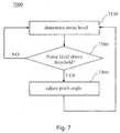
- Fig. 7 shows a flow diagram of a control method 7000 according to an embodiment.
- the noise level at a rotor blade is detected, e.g. by a microphone located at or near the rotor blade.
- the detected noise level is compared with a threshold value to detect a stall condition of the monitored rotor blade. If the noise level is below the threshold value, control method 7000 goes back to first step 7100 and measures the noise level. If the noise level, e.g. the amplitude or time-averaged amplitude, exceeds the threshold value, control method 7000 proceeds to step 7300. In this step, the pitch angle of the monitored rotor blade is adjusted in order to reduce the blade stall.
- control method 7000 goes back to first step 7100 and again measures the noise level. It will be understood by those skilled in the art that this control scheme results in an adjustment of the pitch angle until the noise level falls below the threshold again. Furthermore, it will be understood by those skilled in the art that this control method may be performed independently for each rotor blade.
- the same control scheme may be applied to a sensed vibration level of the monitored rotor blade.
- the pitch angle is adjusted if the vibration level exceeds some predetermined threshold.
- an analysis of the noise and/or vibration frequency spectrum may be performed. Also from such analysis of the frequency spectrum valuable information about the aerodynamical condition of the monitored rotor blade may be extracted. Therefore, the information contained in the frequency spectrum may also be used as a basis for detecting blade stall or another aerodynamical condition.
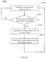
- Fig. 8 shows a flow diagram of a control method 8000 according to another embodiment.
- the basic control scheme of method 8000 is similar to control method 7000.
- the noise and/or vibration level of the monitored rotor blade(s) is determined in a first step 8100.
- the detected noise/vibration level is compared with a threshold value to detect a stall condition of the monitored rotor blade. It should be understood that the threshold may be separately set for noise and vibrations signals. If the noise/vibration level is below the threshold value, control method 8000 goes back to first step 8100 and measures the noise/vibration level. If the noise/vibration level, e.g.
- control method 8000 proceeds to step 8300.
- both noise and vibration are detected and the threshold value will be considered as being exceed if only one of noise and vibration exceeds its respective threshold.
- both noise and vibration are detected but the threshold value will be considered as being exceeded only if both noise and vibration exceed their respective thresholds.
- the rotational position of the monitored rotor blade is determined, e.g. by a rotation sensor located at the rotor shaft.
- the pitch angle of the monitored rotor blade is adjusted in order to reduce the blade stall, thereby taking into account the rotational position of the monitored rotor blade.
- control method 8000 After adjusting the blade pitch angle, control method 8000 goes back to first step 8100 and again measures the noise level. It will be understood by those skilled in the art that this control scheme results in an adjustment of the pitch angle until the noise/vibration level falls below the threshold again. Furthermore, it will be understood by those skilled in the art that this control method may be performed independently for each rotor blade. Like in control method 7000, also frequency analysis may be performed in control method 8000.
Landscapes
- Engineering & Computer Science (AREA)
- Life Sciences & Earth Sciences (AREA)
- Sustainable Development (AREA)
- Sustainable Energy (AREA)
- Chemical & Material Sciences (AREA)
- Combustion & Propulsion (AREA)
- Mechanical Engineering (AREA)
- General Engineering & Computer Science (AREA)
- Physics & Mathematics (AREA)
- Fluid Mechanics (AREA)
- Wind Motors (AREA)
Claims (7)
- Blattverstellsystem (82) für eine Windturbine (10), umfassend eine erste Eingangsklemme (821), die dazu geeignet ist, einen Eingang von wenigstens einem Schwingungssensor (80; 80a, 80b, 80c), der an oder nahe an einem Rotorblatt (8; 8a, 8b, 8c) der Windturbine (10) angeordnet ist, zu erhalten, wobei der Schwingungssensor (80; 80a, 80b, 80c) zur Detektion eines Strömungsabrisszustands des Rotorblatts (8; 8a, 8b, 8c) geeignet ist, wobei das Blattverstellsystem (82) dazu geeignet ist, unter Verwendung des Eingangs von dem Schwingungssensor einen Strömungsabrisszustand des Rotorblatts zu detektieren, um auf der Basis des Sensoreingangs den Anstellwinkel des Rotorblatts zu steuern, um den Strömungsabriss zu verringern; und ferner umfassend eine zweite Eingangsklemme (823), die dazu geeignet ist, einen Eingang von einem Rotationssensor (62), der zur Detektion einer Drehposition (α) einer Rotornabe (4) der Windturbine (10) geeignet ist, zu erhalten wobei das Blattverstellsystem (82) ferner dazu geeignet ist, unter Verwendung des Eingangs von dem Schwingungssensor einen Strömungsabrisszustand des Rotorblatts zu detektieren, um auf der Basis des Eingangs von dem wenigstens einen Schwingungssensor (80; 80a, 80b, 80c) und dem Rotationssensor (62) den Anstellwinkel des Rotorblatts (8; 8a, 8b, 8c) zu steuern, um den Strömungsabriss zu verringern.
- Blattverstellsystem (82) nach einem der vorhergehenden Ansprüche, wobei die Windturbine mehrere Rotorblätter (8a, 8b, 8c) umfasst und das Blattverstellsystem (82) dazu geeignet, ist, den Anstellwinkel jedes Rotorblatts (8a, 8b, 8c) einzeln zu steuern.
- Windturbine (10) mit wenigstens einem Rotorblatt (8), das an einer Rotornabe (4) angebracht ist, wobei die Windturbine ferner wenigstens einen Schwingungssensor (80) umfasst, der an oder nahe an dem Rotorblatt angeordnet ist, wobei der Schwingungssensor (80) zur Detektion eines Strömungsabrisszustands des Rotorblatts geeignet ist, wobei der Anstellwinkel des Rotorblatts durch ein Blattverstellsystem (82) nach einem der vorhergehenden Ansprüche gesteuert werden kann, wobei die Windturbine ein Blattverstellsystem (82) nach einem der vorhergehenden Ansprüche umfasst.
- Verfahren (8000) zum Steuern einer Windturbine (10), umfassend:Detektieren (8100, 8200) eines Strömungsabrisszustands von wenigstens einem Rotorblatt (8) einer Windturbine unter Verwendung eines Schwingungssensors (80), der an oder nahe an dem Rotorblatt angeordnet ist, undEinstellen (8400) des Anstellwinkels des wenigstens einen Rotorblatts, um den Strömungsabriss zu verringern;Detektieren (8300) einer Drehposition (α) des wenigstens einen Rotorblatts (8), wenn der Strömungsabrisszustand detektiert wird;wobei das Einstellen (8400) des Anstellwinkels des wenigstens einen Rotorblatts (8) auf der detektierten Drehposition des Rotorblatts beruht.
- Verfahren (8000) nach Anspruch 4, wobei der Strömungsabrisszustand durch Analysieren eines Schwingungsamplitudensignals detektiert wird, wobei die Schwingung durch den Schwingungssensor (80), der an oder nahe an dem Rotorblatt angeordnet ist, detektiert wird.
- Verfahren (8000) nach Anspruch 5, wobei das Schwingungsamplitudensignal, das analysiert wird, um den Strömungsabrisszustand zu detektieren, ein zeitlich gemitteltes Schwingungsamplitudensignal ist.
- Verfahren (8000) nach einem der Ansprüche 4 bis 6, wobei der Strömungsabrisszustand detektiert wird, wenn ein Sensorsignal, das akustisches Rauschen welches durch das Rotorblatt (8) erzeugt wird, und/oder einen Schwingungszustand des Rotorblatts (8) angibt, einen vorherbestimmten Schwellenwert übersteigt.
Applications Claiming Priority (1)
| Application Number | Priority Date | Filing Date | Title |
|---|---|---|---|
| US11/966,029 US8277185B2 (en) | 2007-12-28 | 2007-12-28 | Wind turbine, wind turbine controller and method for controlling a wind turbine |
Publications (3)
| Publication Number | Publication Date |
|---|---|
| EP2075462A2 EP2075462A2 (de) | 2009-07-01 |
| EP2075462A3 EP2075462A3 (de) | 2012-08-08 |
| EP2075462B1 true EP2075462B1 (de) | 2016-05-18 |
Family
ID=40278632
Family Applications (1)
| Application Number | Title | Priority Date | Filing Date |
|---|---|---|---|
| EP08171280.4A Active EP2075462B1 (de) | 2007-12-28 | 2008-12-11 | Windkraftanlage, Steuerungssystem und Steuerverfahren für Windturbinen |
Country Status (4)
| Country | Link |
|---|---|
| US (1) | US8277185B2 (de) |
| EP (1) | EP2075462B1 (de) |
| CN (1) | CN101469670B (de) |
| DK (1) | DK2075462T3 (de) |
Families Citing this family (71)
| Publication number | Priority date | Publication date | Assignee | Title |
|---|---|---|---|---|
| CN101535634A (zh) * | 2006-10-02 | 2009-09-16 | 维斯塔斯风力系统有限公司 | 风轮机,通过改变叶片桨距减弱风轮机的一个或多个叶片中边沿振荡的方法及其使用 |
| EP2097642B1 (de) * | 2006-12-08 | 2013-08-21 | Vestas Wind Systems A/S | Verfahren zur dämpfung von kanteschwingungen in einer oder mehreren schaufeln einer windturbine, windturbine mit aktiver strömungsabrisssteuerung und verwendung davon |
| WO2008119350A2 (en) * | 2007-03-29 | 2008-10-09 | Vestas Wind Systems A/S | Method for inspecting at least one rotor blade of a wind turbine and inspection system for at least one rotor blade of a wind turbine |
| EP2260281B1 (de) | 2008-03-31 | 2017-05-03 | Vestas Wind Systems A/S | Optischer übertragungsbelastungssensor für windturbinen |
| GB2461532A (en) | 2008-07-01 | 2010-01-06 | Vestas Wind Sys As | Sensor system and method for detecting deformation in a wind turbine component |
| GB2461566A (en) | 2008-07-03 | 2010-01-06 | Vestas Wind Sys As | Embedded fibre optic sensor for mounting on wind turbine components and method of producing the same. |
| GB2463696A (en) | 2008-09-22 | 2010-03-24 | Vestas Wind Sys As | Edge-wise bending insensitive strain sensor system |
| WO2010061255A2 (en) * | 2008-11-01 | 2010-06-03 | Clipper Windpower, Inc. | Active blade pitch control for reduction of wind turbine noise or loads |
| GB2466433B (en) | 2008-12-16 | 2011-05-25 | Vestas Wind Sys As | Turbulence sensor and blade condition sensor system |
| US8186950B2 (en) * | 2008-12-23 | 2012-05-29 | General Electric Company | Aerodynamic device for detection of wind turbine blade operation |
| US7896613B2 (en) * | 2009-06-03 | 2011-03-01 | General Electric Company | System and method for wind turbine noise control and damage detection |
| US7945350B2 (en) * | 2009-07-07 | 2011-05-17 | General Electric Company | Wind turbine acoustic emission control system and method |
| US7902689B2 (en) * | 2009-07-07 | 2011-03-08 | General Electric Company | Method and system for noise controlled operation of a wind turbine |
| GB2472437A (en) | 2009-08-06 | 2011-02-09 | Vestas Wind Sys As | Wind turbine rotor blade control based on detecting turbulence |
| US8360723B2 (en) * | 2009-09-30 | 2013-01-29 | General Electric Company | Method for reducing vibrations in wind turbines and wind turbine implementing said method |
| US20100135790A1 (en) * | 2009-10-14 | 2010-06-03 | Sujan Kumar Pal | Wind turbine blade with foreign matter detection devices |
| GB0919865D0 (en) * | 2009-11-13 | 2009-12-30 | Vestas Wind Sys As | An improvement for wind turbine blade monitoring |
| GB2477529A (en) | 2010-02-04 | 2011-08-10 | Vestas Wind Sys As | A wind turbine optical wind sensor for determining wind speed and direction |
| US8123478B2 (en) * | 2010-05-26 | 2012-02-28 | General Electric Company | Systems and methods for monitoring a condition of a rotor blade for a wind turbine |
| US20110142634A1 (en) * | 2010-06-23 | 2011-06-16 | Detlef Menke | Overspeed protection system and method |
| CA2803481C (en) | 2010-06-30 | 2018-09-25 | Vestas Wind Systems A/S | Wind turbine system for detection of blade icing |
| US20110182730A1 (en) * | 2010-07-27 | 2011-07-28 | Vestas Wind Systems A/S | Wind turbine blade with damping element for edgewise vibrations |
| US20110223006A1 (en) * | 2010-12-06 | 2011-09-15 | Friedrich Loh | System, device, and method for noise-based operation of wind turbines |
| ES2556829T3 (es) * | 2010-12-21 | 2016-01-20 | Vestas Wind Systems A/S | Método de control para una turbina eólica |
| DE102011008561A1 (de) * | 2011-01-14 | 2012-07-19 | Airbus Operations Gmbh | Funktionsüberwachtes Führungssystem zur Verstellung zumindest einer Systemkomponente sowie Verfahren zur Funktionsüberwachung eines solchen Führungssystems |
| WO2012125842A2 (en) * | 2011-03-15 | 2012-09-20 | Purdue Research Foundation | Load shape control of wind turbines |
| US20120257967A1 (en) * | 2011-04-05 | 2012-10-11 | Per Egedal | Method and controller for generating a blade pitch angle control signal and wind turbine comprising the controller |
| EP2565442A1 (de) * | 2011-09-05 | 2013-03-06 | Siemens Aktiengesellschaft | System und Verfahren zum Betreiben einer Windturbine unter Verwendung anpassungsfähiger Bezugsvariabeln |
| ES2626029T3 (es) * | 2011-12-29 | 2017-07-21 | Vestas Wind Systems A/S | Optimización de la producción de energía en una turbina eólica por debajo de la potencia nominal |
| EP2626550B1 (de) * | 2012-02-10 | 2016-04-27 | Siemens Aktiengesellschaft | Verbesserte Rauschunterdrückungssteuerung für Windturbinen |
| CN103291548B (zh) * | 2012-02-29 | 2015-02-25 | 南通大学 | 垂直轴风力机旋转主轴振颤的机电协调抑制装置 |
| US20130259682A1 (en) * | 2012-03-27 | 2013-10-03 | General Electric Company | Method of rotor-stall prevention in wind turbines |
| DK2836706T3 (da) * | 2012-04-11 | 2019-08-19 | Kk Wind Solutions As | Fremgangsmåde til kontrol af en profil af en vinge på en vindmølle |
| EP2679808A1 (de) * | 2012-06-28 | 2014-01-01 | Siemens Aktiengesellschaft | Strömungsabrisserkennung von Windturbinenschaufeln |
| ES2442452B1 (es) * | 2012-07-11 | 2014-12-22 | Acciona Windpower, S.A. | Método de control de aerogenerador |
| CN102758727B (zh) * | 2012-07-11 | 2014-10-08 | 国电联合动力技术有限公司 | 集成于控制系统的风力机状态监测与故障诊断系统及方法 |
| US9581141B2 (en) * | 2012-11-13 | 2017-02-28 | Inventus Holdings, Llc | Early detection of wind turbine degradation using acoustical monitoring |
| US9759196B2 (en) | 2012-11-19 | 2017-09-12 | Elwha Llc | Mitigating wind turbine blade noise generation in response to an atmospheric variation |
| US9435320B2 (en) * | 2012-11-19 | 2016-09-06 | Elwha Llc | Mitigating wind turbine blade noise generation in view of a minimum power generation requirement |
| US9759068B2 (en) * | 2013-02-28 | 2017-09-12 | General Electric Company | System and method for controlling a wind turbine based on identified surface conditions of the rotor blades |
| US9528493B2 (en) | 2013-05-28 | 2016-12-27 | Siemens Aktiengesellschaft | Apparatus to detect aerodynamic conditions of blades of wind turbines |
| EP2818698B1 (de) | 2013-06-28 | 2017-08-09 | Alstom Renovables España, S.L. | Verfahren zum Betrieb einer Windturbine |
| US9593668B2 (en) | 2013-09-10 | 2017-03-14 | General Electric Company | Methods and systems for reducing amplitude modulation in wind turbines |
| DK2857677T3 (en) | 2013-10-01 | 2018-07-02 | Siemens Ag | Adjusting a rotor blade pitch angle |
| US20150132130A1 (en) * | 2013-11-12 | 2015-05-14 | NAB & Associates, Inc. | Wind turbine noise and fatigue control |
| DE102014208681B4 (de) * | 2014-05-08 | 2020-08-20 | iNDTact GmbH | Verfahren zur Überwachung eines Zustands eines in einem Fluid bewegten Rotorblatts |
| US20160327027A1 (en) * | 2014-05-21 | 2016-11-10 | Cheng Ting | Mobile offshore wind turbine |
| US9347432B2 (en) | 2014-07-31 | 2016-05-24 | General Electric Company | System and method for enhanced operation of wind parks |
| US9995277B2 (en) | 2014-07-31 | 2018-06-12 | General Electric Company | System and method for controlling the operation of wind turbines |
| DE102014117918A1 (de) * | 2014-12-04 | 2016-06-09 | fos4X GmbH | Verfahren zur individuellen Pitchregelung von Rotorblättern einer Windkraftanlage, Beschleunigungssensor für ein Rotorblatt, Rotorblatt mit Beschleunigungssensor, ein Rotor einer Windkraftanlage und Windkraftanlagen |
| DK3073108T3 (da) | 2015-03-27 | 2020-01-06 | Siemens Gamesa Renewable Energy As | Styring til en vindmølle |
| US10302064B2 (en) * | 2015-07-30 | 2019-05-28 | The Boeing Company | Methods and systems for rotary wing active flow control |
| DK179069B1 (en) * | 2015-09-04 | 2017-10-02 | Envision Energy Denmark Aps | A wind turbine and a method of operating a wind turbine with a rotational speed exclusion zone |
| DE102015117032A1 (de) | 2015-10-07 | 2017-04-13 | Wobben Properties Gmbh | Verfahren zum Überwachen einer Windenergieanlage |
| DK3384154T3 (da) * | 2015-12-04 | 2021-01-25 | Envision Energy Denmark Aps | En vindturbine og en fremgangsmåde til styring af en vindturbine til reduktion af kantvise svingninger |
| DE102016100522A1 (de) * | 2016-01-13 | 2017-07-13 | Wobben Properties Gmbh | Verfahren zum Bewerten einer Anströmung an einem Rotorblatt einer Windenergieanlage sowie Verfahren zum Steuern einer Windenergieanlage und Windenergieanlage |
| WO2017198270A1 (en) * | 2016-05-18 | 2017-11-23 | Vestas Wind Systems A/S | Analysis of wind turbine noise |
| WO2017198271A1 (en) * | 2016-05-18 | 2017-11-23 | Vestas Wind Systems A/S | Controlling wind turbine noise |
| US11092135B2 (en) | 2016-06-13 | 2021-08-17 | Vestas Wind Systems A/S | Damping of edgewise wind turbine blade vibrations |
| US10907617B2 (en) | 2016-06-30 | 2021-02-02 | Vestas Wind Systems A/S | Diagnostic system and method for use in a wind turbine |
| US10539119B2 (en) | 2017-07-10 | 2020-01-21 | WindESCo, Inc. | System and method for augmenting control of a wind turbine assembly |
| US11078886B2 (en) * | 2018-03-29 | 2021-08-03 | Vestas Offshore Wind A/S | Wind turbine generator and method of controlling wind turbine generator |
| US11261845B2 (en) * | 2018-07-26 | 2022-03-01 | General Electric Company | System and method for protecting wind turbines during extreme wind direction change |
| US11408394B2 (en) * | 2018-09-17 | 2022-08-09 | Siemens Gamesa Renewable Energy A/S | Sensor device for an aerodynamic element |
| DE102018127804B4 (de) * | 2018-11-07 | 2024-07-25 | Vc Viii Polytech Holding Aps | Verbesserung bzw. Optimierung des Ertrags einer Windenergieanlage durch Detektion eines Strömungsabrisses |
| DE102018009334A1 (de) * | 2018-11-28 | 2020-05-28 | Senvion Gmbh | Verfahren zum Betrieb einer Windenergieanlage, Windenergieanlage und Computerprogrammprodukt |
| DE102019125789A1 (de) * | 2019-09-25 | 2021-03-25 | Keba Industrial Automation Germany Gmbh | Pitch-Antriebsregler einer Windkraftanlage, Pitch-Antriebssteuergerät und Verfahren zum Steuern eines Pitch-Antriebsreglers |
| CN113803219B (zh) | 2020-06-15 | 2023-04-18 | 北京金风科创风电设备有限公司 | 风电机组的降载控制方法和装置 |
| EP4239189A1 (de) | 2022-03-02 | 2023-09-06 | General Electric Renovables España S.L. | Schwingungen in windturbinen |
| EP4442990B1 (de) | 2023-04-04 | 2026-05-06 | Nordex Energy SE & Co. KG | Verfahren zum betreiben einer windenergieanlage und windenergieanlage |
| TR2023010280A1 (tr) * | 2023-08-23 | 2025-03-21 | Searover Robotik Ve Yazilim Anonim Sirketi | Rüzgar türbi̇ni̇ kanatlarindaki̇ fi̇zi̇ksel hasar veya buzlanmayi tespi̇t si̇stemi̇ |
Citations (5)
| Publication number | Priority date | Publication date | Assignee | Title |
|---|---|---|---|---|
| US3079105A (en) | 1957-10-21 | 1963-02-26 | Raspet Mabel Wilson | Reserve lift indicator for aircraft and the like |
| WO2002053910A1 (de) | 2000-12-30 | 2002-07-11 | IGUS Ingenieurgemeinschaft Umweltschutz Meß- und Verfahrenstechnik GmbH | Verfahren und einrichtung zur überwachung des zustandes von rotorblättern an windkraftanlagen |
| WO2006012827A1 (de) | 2004-07-28 | 2006-02-09 | Igus - Innovative Technische Systeme Gmbh | Verfahren und vorrichtung zur überwachung des zustandes von rotorblättern an windkraftanlagen |
| WO2007012487A1 (de) | 2005-07-26 | 2007-02-01 | Repower Systems Ag | Windenergieanlage mit einzelpitcheinrichtungen |
| DE102006028167A1 (de) * | 2006-06-16 | 2007-12-20 | Daubner & Stommel Gbr Bau-Werk-Planung | Verfahren zum Betreiben einer zumindest einen fluiddynamischen Auftriebskörper aufweisenden Vorrichtung, insbesondere einer Windenergieanlage |
Family Cites Families (14)
| Publication number | Priority date | Publication date | Assignee | Title |
|---|---|---|---|---|
| US4934192A (en) * | 1988-07-11 | 1990-06-19 | Westinghouse Electric Corp. | Turbine blade vibration detection system |
| US6195982B1 (en) * | 1998-12-30 | 2001-03-06 | United Technologies Corporation | Apparatus and method of active flutter control |
| ES2228121T3 (es) * | 1999-11-03 | 2005-04-01 | Vestas Wind Systems A/S | Procedimiento de control de la operacion de una turbina electrica y turbina electrica para usarse en dicho procedimiento. |
| DE10065314B4 (de) | 2000-12-30 | 2007-08-16 | Igus - Innovative Technische Systeme Gmbh | Verfahren und Einrichtung zur Überwachung des Zustandes von Rotorblättern an Windkraftanlagen |
| US6703718B2 (en) | 2001-10-12 | 2004-03-09 | David Gregory Calley | Wind turbine controller |
| CN1273729C (zh) | 2002-11-13 | 2006-09-06 | 沈阳工业大学 | 兆瓦级风电机组变速、变距控制系统 |
| JP2004293527A (ja) * | 2003-03-28 | 2004-10-21 | Ebara Corp | 風車装置、および風力発電装置 |
| US6940185B2 (en) * | 2003-04-10 | 2005-09-06 | Advantek Llc | Advanced aerodynamic control system for a high output wind turbine |
| CN1734086A (zh) * | 2004-08-11 | 2006-02-15 | 陈晓忠 | 环式风力发电机 |
| EP1856408B1 (de) * | 2005-02-22 | 2017-04-05 | Vestas Wind Systems A/S | Windturbinenblatt |
| NO325856B1 (no) * | 2005-11-01 | 2008-08-04 | Hywind As | Fremgangsmåte for demping av ustabile frie stivlegeme egensvingninger ved en flytende vindturbininstallasjon |
| WO2007089136A2 (en) * | 2006-02-03 | 2007-08-09 | Pantheon Bv | Wind turbine tower vibration damping |
| US8021110B2 (en) * | 2007-01-05 | 2011-09-20 | General Electric Company | Tonal emission control for wind turbines |
| DE102008026842B3 (de) * | 2008-06-05 | 2010-02-18 | Repower Systems Ag | Verfahren und Anordnung zum Überwachen des Betriebs einer Windenergieanlage |
-
2007
- 2007-12-28 US US11/966,029 patent/US8277185B2/en active Active
-
2008
- 2008-12-11 EP EP08171280.4A patent/EP2075462B1/de active Active
- 2008-12-11 DK DK08171280.4T patent/DK2075462T3/da active
- 2008-12-29 CN CN2008101895297A patent/CN101469670B/zh active Active
Patent Citations (6)
| Publication number | Priority date | Publication date | Assignee | Title |
|---|---|---|---|---|
| US3079105A (en) | 1957-10-21 | 1963-02-26 | Raspet Mabel Wilson | Reserve lift indicator for aircraft and the like |
| WO2002053910A1 (de) | 2000-12-30 | 2002-07-11 | IGUS Ingenieurgemeinschaft Umweltschutz Meß- und Verfahrenstechnik GmbH | Verfahren und einrichtung zur überwachung des zustandes von rotorblättern an windkraftanlagen |
| WO2006012827A1 (de) | 2004-07-28 | 2006-02-09 | Igus - Innovative Technische Systeme Gmbh | Verfahren und vorrichtung zur überwachung des zustandes von rotorblättern an windkraftanlagen |
| WO2007012487A1 (de) | 2005-07-26 | 2007-02-01 | Repower Systems Ag | Windenergieanlage mit einzelpitcheinrichtungen |
| CA2616502A1 (en) * | 2005-07-26 | 2007-02-01 | Repower Systems Ag | Wind energy installation with individual pitch devices |
| DE102006028167A1 (de) * | 2006-06-16 | 2007-12-20 | Daubner & Stommel Gbr Bau-Werk-Planung | Verfahren zum Betreiben einer zumindest einen fluiddynamischen Auftriebskörper aufweisenden Vorrichtung, insbesondere einer Windenergieanlage |
Non-Patent Citations (2)
| Title |
|---|
| BRÜEL & KJÆR: "Measuring Vibration", BROCHÜRE, September 1982 (1982-09-01), XP055356419, Retrieved from the Internet <URL:https://www.bksv.com/media/doc/br0094.pdf> |
| TIM ANDREAS FISCHER: "Load Mitigation of an Offshore Wind Turbine by Optimization of Aerodynamic Damping and Vibration Control", THESIS, 31-07-2006, Danmarks Tekniske Universitet, XP055356389, Retrieved from the Internet <URL:http://www.mek.dtu.dk/~/media/Institutter/Mekanik/Sektioner/FVM/uddannelse/eksamensprojekt/mastertheses fm/timfischer2006.ashx> |
Also Published As
| Publication number | Publication date |
|---|---|
| EP2075462A3 (de) | 2012-08-08 |
| DK2075462T3 (da) | 2016-07-18 |
| US20090169378A1 (en) | 2009-07-02 |
| EP2075462A2 (de) | 2009-07-01 |
| CN101469670A (zh) | 2009-07-01 |
| CN101469670B (zh) | 2013-03-06 |
| US8277185B2 (en) | 2012-10-02 |
Similar Documents
| Publication | Publication Date | Title |
|---|---|---|
| EP2075462B1 (de) | Windkraftanlage, Steuerungssystem und Steuerverfahren für Windturbinen | |
| EP1944667B1 (de) | Steuerung der tonalen Emission für Windturbinen | |
| US9644610B2 (en) | Warning a wind turbine generator in a wind park of an extreme wind event | |
| EP2712401B1 (de) | Verbesserte verfahren zur windturbinengeräuschkontrolle | |
| US8096761B2 (en) | Blade pitch management method and system | |
| US20140003938A1 (en) | Stall detection of wind turbine blades | |
| EP2148088A1 (de) | Verfahren und Anordnung zur Anpassung des Anstellwinkels der Windturbinenblätter | |
| US20140030090A1 (en) | Systems and methods for controlling tower clearance in a wind turbine | |
| US20110101696A1 (en) | Wave power plant and method for operating the same | |
| EP2857677B1 (de) | Einstellung eines Rotorschaufelneigungswinkels | |
| CN102549259A (zh) | 具有多个风能装置的风能设备和控制风能设备的方法 | |
| EP2582973A2 (de) | Steuerverfahren für eine windturbine | |
| CA2808040C (en) | Method to control the operation of a wind turbine | |
| US9273671B2 (en) | Method for the identification of the drive train main frequency in a wind turbine | |
| CN118510990A (zh) | 一种减少风力涡轮机叶片振动的方法 | |
| CN111601968B (zh) | 用于控制风能设施的方法和风能设施 | |
| CN113446149B (zh) | 风力发电机组的控制方法和装置 | |
| JP2016145521A (ja) | 風力発電装置 | |
| CN113795666A (zh) | 一种风力发电机及运行该风力发电机的方法 | |
| KR20190085080A (ko) | 빗방울 크기에 기초한 풍력 터빈 제어 | |
| KR101652230B1 (ko) | 풍력 발전기 및 그 제어방법 | |
| EP4423391B1 (de) | Verfahren zum anfahren einer windturbine | |
| ES2577708T3 (es) | Turbina eólica, controlador de turbina eólica y procedimiento de control de una turbina eólica |
Legal Events
| Date | Code | Title | Description |
|---|---|---|---|
| PUAI | Public reference made under article 153(3) epc to a published international application that has entered the european phase |
Free format text: ORIGINAL CODE: 0009012 |
|
| AK | Designated contracting states |
Kind code of ref document: A2 Designated state(s): AT BE BG CH CY CZ DE DK EE ES FI FR GB GR HR HU IE IS IT LI LT LU LV MC MT NL NO PL PT RO SE SI SK TR |
|
| AX | Request for extension of the european patent |
Extension state: AL BA MK RS |
|
| PUAL | Search report despatched |
Free format text: ORIGINAL CODE: 0009013 |
|
| AK | Designated contracting states |
Kind code of ref document: A3 Designated state(s): AT BE BG CH CY CZ DE DK EE ES FI FR GB GR HR HU IE IS IT LI LT LU LV MC MT NL NO PL PT RO SE SI SK TR |
|
| AX | Request for extension of the european patent |
Extension state: AL BA MK RS |
|
| RIC1 | Information provided on ipc code assigned before grant |
Ipc: F03D 7/02 20060101AFI20120629BHEP Ipc: F03D 7/04 20060101ALN20120629BHEP |
|
| 17P | Request for examination filed |
Effective date: 20130208 |
|
| AKX | Designation fees paid |
Designated state(s): DE DK ES |
|
| 17Q | First examination report despatched |
Effective date: 20150710 |
|
| GRAP | Despatch of communication of intention to grant a patent |
Free format text: ORIGINAL CODE: EPIDOSNIGR1 |
|
| RIC1 | Information provided on ipc code assigned before grant |
Ipc: F03D 7/04 20060101ALI20151204BHEP Ipc: F03D 7/02 20060101AFI20151204BHEP |
|
| INTG | Intention to grant announced |
Effective date: 20160104 |
|
| GRAS | Grant fee paid |
Free format text: ORIGINAL CODE: EPIDOSNIGR3 |
|
| GRAA | (expected) grant |
Free format text: ORIGINAL CODE: 0009210 |
|
| AK | Designated contracting states |
Kind code of ref document: B1 Designated state(s): DE DK ES |
|
| REG | Reference to a national code |
Ref country code: DE Ref legal event code: R096 Ref document number: 602008044286 Country of ref document: DE |
|
| REG | Reference to a national code |
Ref country code: ES Ref legal event code: FG2A Ref document number: 2577708 Country of ref document: ES Kind code of ref document: T3 Effective date: 20160718 Ref country code: DK Ref legal event code: T3 Effective date: 20160712 |
|
| REG | Reference to a national code |
Ref country code: DE Ref legal event code: R026 Ref document number: 602008044286 Country of ref document: DE |
|
| PLBI | Opposition filed |
Free format text: ORIGINAL CODE: 0009260 |
|
| PLAX | Notice of opposition and request to file observation + time limit sent |
Free format text: ORIGINAL CODE: EPIDOSNOBS2 |
|
| 26 | Opposition filed |
Opponent name: ENERCON GMBH Effective date: 20170217 |
|
| PLBB | Reply of patent proprietor to notice(s) of opposition received |
Free format text: ORIGINAL CODE: EPIDOSNOBS3 |
|
| PLCK | Communication despatched that opposition was rejected |
Free format text: ORIGINAL CODE: EPIDOSNREJ1 |
|
| STAA | Information on the status of an ep patent application or granted ep patent |
Free format text: STATUS: THE PATENT HAS BEEN GRANTED |
|
| APAH | Appeal reference modified |
Free format text: ORIGINAL CODE: EPIDOSCREFNO |
|
| APBM | Appeal reference recorded |
Free format text: ORIGINAL CODE: EPIDOSNREFNO |
|
| APBP | Date of receipt of notice of appeal recorded |
Free format text: ORIGINAL CODE: EPIDOSNNOA2O |
|
| APBQ | Date of receipt of statement of grounds of appeal recorded |
Free format text: ORIGINAL CODE: EPIDOSNNOA3O |
|
| REG | Reference to a national code |
Ref country code: DE Ref legal event code: R100 Ref document number: 602008044286 Country of ref document: DE |
|
| APBU | Appeal procedure closed |
Free format text: ORIGINAL CODE: EPIDOSNNOA9O |
|
| PLBN | Opposition rejected |
Free format text: ORIGINAL CODE: 0009273 |
|
| STAA | Information on the status of an ep patent application or granted ep patent |
Free format text: STATUS: OPPOSITION REJECTED |
|
| 27O | Opposition rejected |
Effective date: 20220128 |
|
| P01 | Opt-out of the competence of the unified patent court (upc) registered |
Effective date: 20230530 |
|
| REG | Reference to a national code |
Ref country code: DE Ref legal event code: R081 Ref document number: 602008044286 Country of ref document: DE Owner name: GENERAL ELECTRIC RENOVABLES ESPANA, S.L., ES Free format text: FORMER OWNER: GENERAL ELECTRIC COMPANY, SCHENECTADY, NY, US |
|
| REG | Reference to a national code |
Ref country code: ES Ref legal event code: PC2A Owner name: GENERAL ELECTRIC RENOVABLES ESPANA S.L. Effective date: 20240722 |
|
| PGFP | Annual fee paid to national office [announced via postgrant information from national office to epo] |
Ref country code: DE Payment date: 20251126 Year of fee payment: 18 |
|
| PGFP | Annual fee paid to national office [announced via postgrant information from national office to epo] |
Ref country code: DK Payment date: 20251119 Year of fee payment: 18 |
|
| PGFP | Annual fee paid to national office [announced via postgrant information from national office to epo] |
Ref country code: ES Payment date: 20260102 Year of fee payment: 18 |