EP2075470A2 - Compresseur motorisé - Google Patents
Compresseur motorisé Download PDFInfo
- Publication number
- EP2075470A2 EP2075470A2 EP08171965A EP08171965A EP2075470A2 EP 2075470 A2 EP2075470 A2 EP 2075470A2 EP 08171965 A EP08171965 A EP 08171965A EP 08171965 A EP08171965 A EP 08171965A EP 2075470 A2 EP2075470 A2 EP 2075470A2
- Authority
- EP
- European Patent Office
- Prior art keywords
- housing
- motor
- driven compressor
- mounting
- rotary shaft
- Prior art date
- Legal status (The legal status is an assumption and is not a legal conclusion. Google has not performed a legal analysis and makes no representation as to the accuracy of the status listed.)
- Granted
Links
Images

Classifications
-
- F—MECHANICAL ENGINEERING; LIGHTING; HEATING; WEAPONS; BLASTING
- F04—POSITIVE - DISPLACEMENT MACHINES FOR LIQUIDS; PUMPS FOR LIQUIDS OR ELASTIC FLUIDS
- F04C—ROTARY-PISTON, OR OSCILLATING-PISTON, POSITIVE-DISPLACEMENT MACHINES FOR LIQUIDS; ROTARY-PISTON, OR OSCILLATING-PISTON, POSITIVE-DISPLACEMENT PUMPS
- F04C18/00—Rotary-piston pumps specially adapted for elastic fluids
- F04C18/02—Rotary-piston pumps specially adapted for elastic fluids of arcuate-engagement type, i.e. with circular translatory movement of co-operating members, each member having the same number of teeth or tooth-equivalents
- F04C18/0207—Rotary-piston pumps specially adapted for elastic fluids of arcuate-engagement type, i.e. with circular translatory movement of co-operating members, each member having the same number of teeth or tooth-equivalents both members having co-operating elements in spiral form
- F04C18/0215—Rotary-piston pumps specially adapted for elastic fluids of arcuate-engagement type, i.e. with circular translatory movement of co-operating members, each member having the same number of teeth or tooth-equivalents both members having co-operating elements in spiral form where only one member is moving
-
- F—MECHANICAL ENGINEERING; LIGHTING; HEATING; WEAPONS; BLASTING
- F04—POSITIVE - DISPLACEMENT MACHINES FOR LIQUIDS; PUMPS FOR LIQUIDS OR ELASTIC FLUIDS
- F04C—ROTARY-PISTON, OR OSCILLATING-PISTON, POSITIVE-DISPLACEMENT MACHINES FOR LIQUIDS; ROTARY-PISTON, OR OSCILLATING-PISTON, POSITIVE-DISPLACEMENT PUMPS
- F04C29/00—Component parts, details or accessories of pumps or pumping installations, not provided for in groups F04C18/00 - F04C28/00
- F04C29/04—Heating; Cooling; Heat insulation
- F04C29/047—Cooling of electronic devices installed inside the pump housing, e.g. inverters
-
- F—MECHANICAL ENGINEERING; LIGHTING; HEATING; WEAPONS; BLASTING
- F04—POSITIVE - DISPLACEMENT MACHINES FOR LIQUIDS; PUMPS FOR LIQUIDS OR ELASTIC FLUIDS
- F04C—ROTARY-PISTON, OR OSCILLATING-PISTON, POSITIVE-DISPLACEMENT MACHINES FOR LIQUIDS; ROTARY-PISTON, OR OSCILLATING-PISTON, POSITIVE-DISPLACEMENT PUMPS
- F04C2230/00—Manufacture
- F04C2230/60—Assembly methods
- F04C2230/604—Mounting devices for pumps or compressors
-
- F—MECHANICAL ENGINEERING; LIGHTING; HEATING; WEAPONS; BLASTING
- F04—POSITIVE - DISPLACEMENT MACHINES FOR LIQUIDS; PUMPS FOR LIQUIDS OR ELASTIC FLUIDS
- F04C—ROTARY-PISTON, OR OSCILLATING-PISTON, POSITIVE-DISPLACEMENT MACHINES FOR LIQUIDS; ROTARY-PISTON, OR OSCILLATING-PISTON, POSITIVE-DISPLACEMENT PUMPS
- F04C2240/00—Components
- F04C2240/80—Other components
- F04C2240/808—Electronic circuits (e.g. inverters) installed inside the machine
Definitions
- the present invention relates to a motor-driven compressor having a compression mechanism, an electric motor, and a motor drive circuit which are disposed along the axial direction of a drive shaft of the compressor.
- the outer shell of the motor-driven compressor disclosed in the above reference includes a main housing and a front housing.
- the main housing is made of an aluminum alloy and formed in a cylindrical shape.
- the front housing is formed in the shape of a cover and connected to the front end of the main housing.
- the main housing of the motor-driven compressor accommodates therein an electric motor substantially at the center, a compression mechanism in the front, and a motor drive circuit in the rear.
- the electric motor has a stator fixed to the inner peripheral surface of the housing and a rotor mounted on the drive shaft inside of the stator.
- the compression mechanism is fixed to the inner peripheral surface of the main housing, and mounted on the drive shaft which is driven to rotate by the electric motor.
- the motor-driven compressor is formed integrally at each of the top and bottom of its outer periphery with a pair of mounting lugs for mounting the motor-driven compressor on a vehicle engine (an object to which the motor-driven compressor is to be mounted).
- the mounting lugs of each pair are spaced in the axial direction of the housing.
- Bolts fastening members are inserted through holes formed through the mounting lugs and screwed into bosses extending from the vehicle engine, so that the motor-driven compressor is mounted on the vehicle engine.
- the mounting lugs of the main housing is formed at positions outside of the compression mechanism and the electric motor along the axial direction of the main housing. Since the mounting lugs are formed integrally with the main housing, the main housing may be deformed due to differences of the clamping forces of the bolts, poor dimensional accuracy of the bosses, and the like when the mounting lugs are fastened to the bosses by the bolts. As a result, the compression mechanism and the electric motor fixed to the main housing may be displaced out of alignment, and the rotary shaft is displaced out of axial alignment. This causes unwanted noise and deterioration of the durability of bearings supporting the rotary shaft.
- the present invention is directed to providing a motor-driven compressor in which a first housing (main housing) can be prevented from being deformed by fastening of the mounting lugs to an object to which the motor-driven compressor is to be mounted by means of fastening members.
- a motor-driven compressor has a compression mechanism, a rotary shaft, an electric motor, a motor drive circuit and a housing assembly.
- the compression mechanism compresses a refrigerant gas.
- the rotary shaft rotates to drive the compression mechanism.
- the electric motor is connected to the rotary shaft.
- the motor drive circuit is used for driving the electric motor.
- the compression mechanism, the electric motor and the motor drive circuit are disposed along the axial direction of the rotary shaft in the housing assembly.
- the housing assembly has a first housing for mounting the electric motor and the compression mechanism.
- the first housing has first and second mounting lugs formed integrally with the peripheral surface of the first housing on the radially opposite sides of the rotary shaft.
- the second housing is joined to the first housing for accommodating the motor drive circuit.
- the second housing has a third mounting lug formed integrally with the second housing.
- the first through third mounting lugs are fastenable to a mounting object on which the motor-driven compressor is to be mounted by means of fastening members
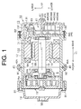
- Figs. 1 and 2 The following will describe the preferred embodiment with reference to Figs. 1 and 2 , in which the present invention is applied to a motor-driven compressor mounted on a hybrid vehicle and used for a vehicle air conditioner.
- the front and rear sides of the motor-driven compressor as will be referred to in the following description are indicated by the double-headed arrow Y1 in Fig. 1 .
- the upper and lower sides of the motor-driven compressor are indicated by the double-headed arrow Y2 in Fig. 1 .
- the motor-driven compressor generally designated by reference numeral 10 has a housing assembly including a first housing 12, a second housing 13 and a third hosing 14. Major part of the housing assembly is formed by the first housing 12. As shown in Fig. 1 , the second housing 13 is connected to the rear end of the first housing 12, and the third housing 14 is connected to the front end of the first housing 12.
- the first housing 12 is made of a die-cast aluminum alloy, and has a cylindrical shape with one end closed. Specifically, the first housing 12 includes a rear wall portion 121 and a cylindrical wall portion 122 extending from the entire periphery of the rear wall portion 121.
- the second housing 13 is also made of a die-cast aluminum alloy, and has a cylindrical shape with one end closed.
- the second housing 13 includes a cover portion 131 and a cylindrical wall portion 132 extending from the entire periphery of the cover portion 131.
- the third housing 14 is also made of a die-cast aluminum alloy and has a cylindrical shape with front end closed.
- the first housing 12 and the second housing 13 are fastened together by means of four second bolts B2 (only two second bolts B2 is shown in Fig. 1 ), and the first housing 12 and the third housing 14 are fastened together by means of four first bolts B1 (only two first bolts B1 is shown in Fig .1 ).
- the first housing 12 and the third housing 14 collectively define therebetween a closed space S, in which the rotary shaft 16 is rotatably supported by bearings 15 disposed in the front and rear of the first housing 12.
- Reference symbol L in Fig. 1 indicates the central axis of the rotary shaft 16, and the direction of the central axis L corresponds to the axial direction of the first housing 12 and hence of the motor-driven compressor 10.
- the first housing 12 is arranged in the motor-driven compressor 10 such that the cylindrical wall portion 122 thereof surrounds the rotary shaft 16 and the central axis L.
- the first housing 12 has therein an electric motor 18 and a compression mechanism 19 which are fixedly mounted thereon.
- the electric motor 18 has a stator 18A fixed to the inner peripheral surface of the cylindrical wall portion 122 of the first housing 12 and a rotor 18B mounted on the rotary shaft 16 of the first housing 12 inside of the stator 18A. Electrical power is supplied to the stator 18A, and the electric motor 18 drives to rotate the rotary shaft 16.
- the compression mechanism 19 is of a scroll type, having a fixed scroll 19A and a movable scroll 19B.
- the movable scroll 19B orbits around the fixed scroll 19A in accordance with the rotation of the rotary shaft 16, and the compression mechanism 19 compresses refrigerant gas.
- the electric motor 18 drives to rotate the rotary shaft 16, which in turn drives the compression mechanism 19.
- Refrigerant gas in an external refrigerant circuit (not shown) under a relatively low temperature and low pressure is suctioned into the closed space S through a suction port 31 formed through the first housing 12. Then refrigerant gas is flowed through the electric motor 18, and then into the compression mechanism 19.
- refrigerant gas is compressed by the compression mechanism 19, and the refrigerant gas compressed into a high temperature and high pressure gas is discharged to the external refrigerant circuit through a discharge port 32 formed through the third housing 14.
- the configuration of allowing the refrigerant gas flowing from the external refrigerant circuit and having relatively low temperature to flow through the electric motor 18 in the closed space S before being introduced into the compression mechanism 19 is to cool both the electric motor 18 and a motor drive circuit 41 which will be described later.
- the rear wall portion 121 of the first housing 12 and the second housing 13 cooperate to define therebetween an accommodation space T for accommodating therein the motor drive circuit 41.
- the accommodation space T is defined by rear end surface of the rear wall portion 121 of the first housing 12 and the inner peripheral surface of the second housing 13.
- the accommodation space T has therein the motor drive circuit 41 which is used for driving the electric motor 18.
- the motor drive circuit 41 serving as an inverter supplies electrical power to the stator 18A of the electric motor 18 in response to control signals from an electrical control unit (ECU) of the vehicle air conditioner (not shown).
- ECU electrical control unit
- the motor drive circuit 41 has a plate-like circuit board 43 and various kinds of electronic components 44 mounted on the circuit board 43.
- Reference numeral 44 generally indicates various electronic components 44A through 44E which will be described later, and other related components (not shown).
- the electronic components 44 include known electronic components 44A through 44E for inverter such as switching devices 44A, and an electrolytic capacitor 44B, a transformer 44C, a driver IC 44D, a resistor 44E, and the like.
- the switching devices 44A are mounted on the front side of the circuit board 43 adjacent to the first housing 12.
- the switching devices 44A are provided with the front side surface thereof adjacent to the first housing 12 set in contact with the first housing 12.
- the first housing 12 has a connecting terminal 30 fixed to the rear wall portion 121 of the first housing 12.
- the connecting terminal 30 is electrically connected at one end thereof to the circuit board 43 and at the other end thereof to the stator 18A through lead wires 33, 34, respectively.
- the compression mechanism 19, the electric motor 18 and the motor drive circuit 41 are disposed in the housing assembly of the motor-driven compressor 10 in this order along the axial direction of the rotary shaft 16.
- the housing assembly of the motor-driven compressor 10 is formed with a first mounting lug 45, a second mounting lug 46 and a third mounting lug 47 for mounting the motor-driven compressor 10 to a hybrid vehicle engine E.
- the hybrid vehicle engine E is an object on which the motor-driven compressor 10 is to be mounted.
- the first mounting lug 45 is formed integrally with the first housing 12 at the top outer peripheral surface of the cylindrical wall portion 122 thereof, and formed in an elongated cylindrical shape perpendicular to the central axis L of the rotary shaft 16.
- the first mounting lug 45 has a first hole 45A formed therethrough perpendicular to the central axis L of the rotary shaft 16.
- the second mounting lug 46 is formed integrally with the first housing 12 at the bottom outer peripheral surface of the cylindrical wall portion 122 thereof, and formed in an elongated cylindrical shape extending perpendicular to the central axis L of the rotary shaft 16.
- the second mounting lug 46 has a second hole 46A formed therethrough perpendicular to the central axis L of the rotary shaft 16.
- the first and second mounting lugs 45, 46 are formed on the opposite top and bottom sides of the first housing 12 as seen from the rotary shaft 16, and extend with the central axes N1, N2 thereof in parallel to each other.
- the first and second mounting lugs 45, 46 are formed with the same length as measured in a direction of the central axes N1, N2.
- the right end surfaces of the first and second mounting lugs 45, 46 as seen in Fig. 2 are located in a virtual plane H1, and the opposite left end surface thereof are located in a virtual plane H2.
- the first and second mounting lugs 45, 46 are provided on the cylindrical wall portion 122 of the first housing 12 at a position between the electric motor 18 and the compression mechanism 19 as seen in the axial direction of the first housing 12.
- the first and the second mounting lugs 45, 46 are located on the radially opposite top and bottom sides of the first housing 12 or the cylindrical wall portion 122 as seen from the rotary shaft 16.
- the third mounting lug 47 is formed integrally with the second housing 13 at the center of the outer surface of the cover portion 131 thereof, and formed into an elongated cylindrical shape extending perpendicular to the central axis L of the rotary shaft 16.
- the third mounting lug 47 has a third hole 47A formed therethrough extending perpendicular to the central axis L of the rotary shaft 16.
- the third mounting lug 47 is provided in the second housing 13 at a position furthest from the compression mechanism 19 in the axial direction of the first housing 12.
- Reference symbol M in Fig. 1 indicates the distance between the central axis N1 of the first mounting lug 45 and the central axis N2 of the second mounting lug 46.
- the axis N3 of the third mounting lug 47 is vertically located at the middle point of the distance M, as well as at the central axis L of the rotary shaft 16.
- the third mounting lug 47 is formed in the second housing 13 such that the central axis N3 thereof is in parallel relation to the central axes N1, N2 of the first and second mounting lugs 45, 46.
- the first, second and third mounting lugs 45, 46, 47 have the same length as measured in the extending direction of the central axes N1, N2, N3 thereof.
- the first, second and third mounting lugs 45, 46, 47 are formed with the right end surface thereof as seen in Fig. 2 located in the virtual plane H1, and the left end surface thereof located in the virtual plane H2, respectively.
- Third bolts B3 serving as a fastening member are inserted through the respective holes 45A, 46A, 47A of the first, second and third mounting lugs 45, 46, 47 and screwed into the bosses E1, E2, E3 formed in the vehicle engine E, respectively.
- the electric-motor compressor 10 is mounted on a side surface of the vehicle engine E.
- the electric motor 18, the compression mechanism 19 and the motor drive circuit 41 may be arranged along the axial direction of the rotary shaft 16 in this order in the housing assembly of the motor-driven compressor 10.
- Two or more mounting lugs may be provided in the second housing 13.
- the third mounting lug 47 may be formed integrally with the wall portion 132 of the second housing 13.
- bolts are used as a fastening member.
- the fastening member is not limited to the bolts, but any other fastening members such as screws are acceptable.
- the compression mechanism 19 is not limited to a scroll type, but it may be of a piston type or a vane type.
- the motor-driven compressor 10 is installed on a hybrid vehicle.
- the motor-driven compressor 10 may be installed on a vehicle powered solely by an engine.
- the motor-driven compressor 10 of the above preferred embodiment has been described as applied to a vehicle air conditioner.
- the motor-driven compressor 10 may be used for an air conditioner for applications other than vehicles.
- the motor-driven compressor 10 is connected to the vehicle engine E as an object on which the motor-driven compressor 10 is to be mounted.
- the motor-driven compressor 10 may be connected to a body forming an engine room of a hybrid vehicle as the object.
- a motor-driven compressor has a compression mechanism, a rotary shaft, an electric motor, a motor drive circuit and a housing assembly.
- the compression mechanism, the electric motor and the motor drive circuit are disposed along the axial direction of the rotary shaft in the housing assembly.
- the housing assembly has first and second housings.
- the first housing mounts the electric motor and the compression mechanism.
- the first housing has first and second mounting lugs formed integrally with the peripheral surface of the first housing.
- the second housing is joined to the first housing for accommodating the motor drive circuit.
- the second housing has a third mounting lug formed integrally with the second housing. The first through third mounting lugs are fastened to a mounting object to which the motor-driven compressor is to be mounted by means of fastening members.
Landscapes
- Engineering & Computer Science (AREA)
- Mechanical Engineering (AREA)
- General Engineering & Computer Science (AREA)
- Applications Or Details Of Rotary Compressors (AREA)
- Compressor (AREA)
- Connection Of Motors, Electrical Generators, Mechanical Devices, And The Like (AREA)
Applications Claiming Priority (1)
| Application Number | Priority Date | Filing Date | Title |
|---|---|---|---|
| JP2007326415A JP5018450B2 (ja) | 2007-12-18 | 2007-12-18 | 電動圧縮機 |
Publications (3)
| Publication Number | Publication Date |
|---|---|
| EP2075470A2 true EP2075470A2 (fr) | 2009-07-01 |
| EP2075470A3 EP2075470A3 (fr) | 2015-05-06 |
| EP2075470B1 EP2075470B1 (fr) | 2017-04-19 |
Family
ID=40547917
Family Applications (1)
| Application Number | Title | Priority Date | Filing Date |
|---|---|---|---|
| EP08171965.0A Active EP2075470B1 (fr) | 2007-12-18 | 2008-12-17 | Compresseur motorisé |
Country Status (4)
| Country | Link |
|---|---|
| US (1) | US8152490B2 (fr) |
| EP (1) | EP2075470B1 (fr) |
| JP (1) | JP5018450B2 (fr) |
| CN (1) | CN101463814B (fr) |
Cited By (3)
| Publication number | Priority date | Publication date | Assignee | Title |
|---|---|---|---|---|
| US8974197B2 (en) | 2010-02-16 | 2015-03-10 | Halla Visteon Climate Control Corporation | Compact structure for an electric compressor |
| EP3236070A4 (fr) * | 2014-12-18 | 2017-12-20 | Panasonic Intellectual Property Management Co., Ltd. | Compresseur électrique |
| EP3875761A4 (fr) * | 2018-10-30 | 2022-08-03 | Valeo Japan Co., Ltd | Structure de renforcement pour compresseur à entraînement électrique |
Families Citing this family (15)
| Publication number | Priority date | Publication date | Assignee | Title |
|---|---|---|---|---|
| US8777591B2 (en) * | 2010-02-16 | 2014-07-15 | Heng Sheng Precision Tech. Co., Ltd. | Electrically driven compressor system for vehicles |
| JP5478444B2 (ja) * | 2010-09-20 | 2014-04-23 | 株式会社ヴァレオジャパン | 圧縮機 |
| JP5252020B2 (ja) * | 2011-03-25 | 2013-07-31 | 株式会社豊田自動織機 | ポンプの取付構造 |
| CA2802466A1 (fr) | 2012-01-17 | 2013-07-17 | Regal Beloit America, Inc. | Moteur electrique |
| JP5423821B2 (ja) | 2012-01-20 | 2014-02-19 | 株式会社豊田自動織機 | 電動圧縮機、及び電動圧縮機の製造方法 |
| JP5867313B2 (ja) * | 2012-06-28 | 2016-02-24 | 株式会社豊田自動織機 | 電動圧縮機 |
| JP5699994B2 (ja) * | 2012-06-29 | 2015-04-15 | 株式会社豊田自動織機 | 電動圧縮機 |
| JP6203492B2 (ja) * | 2012-12-28 | 2017-09-27 | 三菱重工業株式会社 | インバータ一体型電動圧縮機 |
| JP2017017975A (ja) * | 2015-06-30 | 2017-01-19 | 株式会社豊田自動織機 | 電動コンプレッサ |
| JP2017180213A (ja) * | 2016-03-29 | 2017-10-05 | 株式会社豊田自動織機 | 電動圧縮機 |
| JP6658432B2 (ja) * | 2016-09-29 | 2020-03-04 | 株式会社豊田自動織機 | 車載用流体機械 |
| US10830223B2 (en) * | 2016-11-30 | 2020-11-10 | Dare Auto Inc. | Pump system |
| JP6955220B2 (ja) * | 2018-03-30 | 2021-10-27 | 株式会社豊田自動織機 | 電動圧縮機 |
| DE102019131791B8 (de) * | 2019-11-25 | 2022-10-13 | Hanon Systems | Anordnungen zum Verbinden elektrischer Anschlüsse für eine Vorrichtung zum Antreiben eines Verdichters sowie Verfahren zum Montieren der Anordnungen und Vorrichtung zum Antreiben eines Verdichters sowie Verwendung der Vorrichtung |
| JP7817102B2 (ja) * | 2022-07-22 | 2026-02-18 | サンデン株式会社 | 電動圧縮機 |
Citations (1)
| Publication number | Priority date | Publication date | Assignee | Title |
|---|---|---|---|---|
| JP2004324494A (ja) | 2003-04-23 | 2004-11-18 | Denso Corp | 電動圧縮機 |
Family Cites Families (10)
| Publication number | Priority date | Publication date | Assignee | Title |
|---|---|---|---|---|
| JP3512857B2 (ja) | 1994-06-10 | 2004-03-31 | 株式会社デンソー | スクロール型圧縮機及びそのマウント方法 |
| JP2000291557A (ja) | 1999-04-07 | 2000-10-17 | Sanden Corp | 電動式圧縮機 |
| JP4048311B2 (ja) * | 2000-03-17 | 2008-02-20 | 株式会社豊田自動織機 | 電動圧縮機 |
| JP2002266766A (ja) * | 2001-03-07 | 2002-09-18 | Toyota Industries Corp | 圧縮機 |
| JP2004218585A (ja) | 2003-01-16 | 2004-08-05 | Toyota Industries Corp | 圧縮機及び圧縮機のハウジングの製造方法 |
| JP2005155369A (ja) * | 2003-11-21 | 2005-06-16 | Toyota Industries Corp | 電動圧縮機 |
| JP2006348928A (ja) * | 2004-10-14 | 2006-12-28 | Matsushita Electric Ind Co Ltd | 圧縮機 |
| JP2006177231A (ja) * | 2004-12-22 | 2006-07-06 | Matsushita Electric Ind Co Ltd | 電動圧縮機 |
| JP2006207391A (ja) * | 2005-01-25 | 2006-08-10 | Sanden Corp | 流体機械 |
| JP2006283694A (ja) * | 2005-04-01 | 2006-10-19 | Sanden Corp | スクロール型流体機械 |
-
2007
- 2007-12-18 JP JP2007326415A patent/JP5018450B2/ja active Active
-
2008
- 2008-12-12 US US12/334,025 patent/US8152490B2/en active Active
- 2008-12-16 CN CN200810186651.9A patent/CN101463814B/zh active Active
- 2008-12-17 EP EP08171965.0A patent/EP2075470B1/fr active Active
Patent Citations (1)
| Publication number | Priority date | Publication date | Assignee | Title |
|---|---|---|---|---|
| JP2004324494A (ja) | 2003-04-23 | 2004-11-18 | Denso Corp | 電動圧縮機 |
Cited By (4)
| Publication number | Priority date | Publication date | Assignee | Title |
|---|---|---|---|---|
| US8974197B2 (en) | 2010-02-16 | 2015-03-10 | Halla Visteon Climate Control Corporation | Compact structure for an electric compressor |
| EP3236070A4 (fr) * | 2014-12-18 | 2017-12-20 | Panasonic Intellectual Property Management Co., Ltd. | Compresseur électrique |
| US10421334B2 (en) | 2014-12-18 | 2019-09-24 | Panasonic Intellectual Property Management Co., Ltd. | Electric compressor |
| EP3875761A4 (fr) * | 2018-10-30 | 2022-08-03 | Valeo Japan Co., Ltd | Structure de renforcement pour compresseur à entraînement électrique |
Also Published As
| Publication number | Publication date |
|---|---|
| EP2075470A3 (fr) | 2015-05-06 |
| US8152490B2 (en) | 2012-04-10 |
| EP2075470B1 (fr) | 2017-04-19 |
| JP2009150236A (ja) | 2009-07-09 |
| JP5018450B2 (ja) | 2012-09-05 |
| US20090151389A1 (en) | 2009-06-18 |
| CN101463814B (zh) | 2013-05-29 |
| CN101463814A (zh) | 2009-06-24 |
Similar Documents
| Publication | Publication Date | Title |
|---|---|---|
| EP2075470B1 (fr) | Compresseur motorisé | |
| US8618703B2 (en) | Motor driven compressor | |
| EP2072754B1 (fr) | Compresseur motorisé avec un carter en plusieurs éléments | |
| JP2002070743A (ja) | 冷媒圧縮用電動式圧縮機 | |
| KR101919062B1 (ko) | 차량 탑재용 유체 기계 | |
| CN111120249B (zh) | 电动压缩机 | |
| CN101548105B (zh) | 电动压缩机 | |
| JP6601246B2 (ja) | 電動圧縮機 | |
| JP2009250173A (ja) | 電動圧縮機 | |
| EP1382849A2 (fr) | Compresseur électrique | |
| EP1382848A2 (fr) | Compresseur électrique et son système de contrôle | |
| EP2623786B1 (fr) | Compresseur motorisé | |
| JP5194766B2 (ja) | インバータ一体型電動圧縮機 | |
| JP4225101B2 (ja) | 電動圧縮機 | |
| KR101986450B1 (ko) | 전동 압축기 | |
| JP2006177231A (ja) | 電動圧縮機 | |
| JP5906378B2 (ja) | 電動圧縮機 | |
| CN101146998A (zh) | 电动压缩机 | |
| JP2002180984A (ja) | 冷媒圧縮用電動式圧縮機 | |
| EP4138275A1 (fr) | Couvercle d'un boîtier d'une machine électrique | |
| US20260078757A1 (en) | Magnetic debris filter for compressor and compressor with magnetic debris filter | |
| US20260078758A1 (en) | Oil separator for compressor and compressor with oil separator | |
| JP5931488B2 (ja) | 電動圧縮機 | |
| JP2012021473A (ja) | 電動圧縮機 | |
| JP2004019586A (ja) | 電動圧縮機 |
Legal Events
| Date | Code | Title | Description |
|---|---|---|---|
| PUAI | Public reference made under article 153(3) epc to a published international application that has entered the european phase |
Free format text: ORIGINAL CODE: 0009012 |
|
| 17P | Request for examination filed |
Effective date: 20081217 |
|
| AK | Designated contracting states |
Kind code of ref document: A2 Designated state(s): AT BE BG CH CY CZ DE DK EE ES FI FR GB GR HR HU IE IS IT LI LT LU LV MC MT NL NO PL PT RO SE SI SK TR |
|
| AX | Request for extension of the european patent |
Extension state: AL BA MK RS |
|
| PUAL | Search report despatched |
Free format text: ORIGINAL CODE: 0009013 |
|
| AK | Designated contracting states |
Kind code of ref document: A3 Designated state(s): AT BE BG CH CY CZ DE DK EE ES FI FR GB GR HR HU IE IS IT LI LT LU LV MC MT NL NO PL PT RO SE SI SK TR |
|
| AX | Request for extension of the european patent |
Extension state: AL BA MK RS |
|
| RIC1 | Information provided on ipc code assigned before grant |
Ipc: F04C 18/02 20060101AFI20150405BHEP Ipc: F04C 29/04 20060101ALI20150405BHEP |
|
| AKX | Designation fees paid |
Designated state(s): AT BE BG CH CY CZ DE DK EE ES FI FR GB GR HR HU IE IS IT LI LT LU LV MC MT NL NO PL PT RO SE SI SK TR |
|
| AXX | Extension fees paid |
Extension state: MK Extension state: AL Extension state: RS Extension state: BA |
|
| 17Q | First examination report despatched |
Effective date: 20160301 |
|
| GRAP | Despatch of communication of intention to grant a patent |
Free format text: ORIGINAL CODE: EPIDOSNIGR1 |
|
| INTG | Intention to grant announced |
Effective date: 20161114 |
|
| GRAS | Grant fee paid |
Free format text: ORIGINAL CODE: EPIDOSNIGR3 |
|
| GRAA | (expected) grant |
Free format text: ORIGINAL CODE: 0009210 |
|
| AK | Designated contracting states |
Kind code of ref document: B1 Designated state(s): AT BE BG CH CY CZ DE DK EE ES FI FR GB GR HR HU IE IS IT LI LT LU LV MC MT NL NO PL PT RO SE SI SK TR |
|
| REG | Reference to a national code |
Ref country code: GB Ref legal event code: FG4D |
|
| REG | Reference to a national code |
Ref country code: CH Ref legal event code: EP |
|
| REG | Reference to a national code |
Ref country code: AT Ref legal event code: REF Ref document number: 886248 Country of ref document: AT Kind code of ref document: T Effective date: 20170515 |
|
| REG | Reference to a national code |
Ref country code: IE Ref legal event code: FG4D |
|
| REG | Reference to a national code |
Ref country code: DE Ref legal event code: R096 Ref document number: 602008049808 Country of ref document: DE |
|
| REG | Reference to a national code |
Ref country code: NL Ref legal event code: MP Effective date: 20170419 |
|
| REG | Reference to a national code |
Ref country code: LT Ref legal event code: MG4D |
|
| REG | Reference to a national code |
Ref country code: AT Ref legal event code: MK05 Ref document number: 886248 Country of ref document: AT Kind code of ref document: T Effective date: 20170419 |
|
| PG25 | Lapsed in a contracting state [announced via postgrant information from national office to epo] |
Ref country code: NL Free format text: LAPSE BECAUSE OF FAILURE TO SUBMIT A TRANSLATION OF THE DESCRIPTION OR TO PAY THE FEE WITHIN THE PRESCRIBED TIME-LIMIT Effective date: 20170419 |
|
| PG25 | Lapsed in a contracting state [announced via postgrant information from national office to epo] |
Ref country code: GR Free format text: LAPSE BECAUSE OF FAILURE TO SUBMIT A TRANSLATION OF THE DESCRIPTION OR TO PAY THE FEE WITHIN THE PRESCRIBED TIME-LIMIT Effective date: 20170720 Ref country code: LT Free format text: LAPSE BECAUSE OF FAILURE TO SUBMIT A TRANSLATION OF THE DESCRIPTION OR TO PAY THE FEE WITHIN THE PRESCRIBED TIME-LIMIT Effective date: 20170419 Ref country code: ES Free format text: LAPSE BECAUSE OF FAILURE TO SUBMIT A TRANSLATION OF THE DESCRIPTION OR TO PAY THE FEE WITHIN THE PRESCRIBED TIME-LIMIT Effective date: 20170419 Ref country code: NO Free format text: LAPSE BECAUSE OF FAILURE TO SUBMIT A TRANSLATION OF THE DESCRIPTION OR TO PAY THE FEE WITHIN THE PRESCRIBED TIME-LIMIT Effective date: 20170719 Ref country code: FI Free format text: LAPSE BECAUSE OF FAILURE TO SUBMIT A TRANSLATION OF THE DESCRIPTION OR TO PAY THE FEE WITHIN THE PRESCRIBED TIME-LIMIT Effective date: 20170419 Ref country code: HR Free format text: LAPSE BECAUSE OF FAILURE TO SUBMIT A TRANSLATION OF THE DESCRIPTION OR TO PAY THE FEE WITHIN THE PRESCRIBED TIME-LIMIT Effective date: 20170419 Ref country code: AT Free format text: LAPSE BECAUSE OF FAILURE TO SUBMIT A TRANSLATION OF THE DESCRIPTION OR TO PAY THE FEE WITHIN THE PRESCRIBED TIME-LIMIT Effective date: 20170419 |
|
| PG25 | Lapsed in a contracting state [announced via postgrant information from national office to epo] |
Ref country code: IS Free format text: LAPSE BECAUSE OF FAILURE TO SUBMIT A TRANSLATION OF THE DESCRIPTION OR TO PAY THE FEE WITHIN THE PRESCRIBED TIME-LIMIT Effective date: 20170819 Ref country code: LV Free format text: LAPSE BECAUSE OF FAILURE TO SUBMIT A TRANSLATION OF THE DESCRIPTION OR TO PAY THE FEE WITHIN THE PRESCRIBED TIME-LIMIT Effective date: 20170419 Ref country code: SE Free format text: LAPSE BECAUSE OF FAILURE TO SUBMIT A TRANSLATION OF THE DESCRIPTION OR TO PAY THE FEE WITHIN THE PRESCRIBED TIME-LIMIT Effective date: 20170419 Ref country code: BG Free format text: LAPSE BECAUSE OF FAILURE TO SUBMIT A TRANSLATION OF THE DESCRIPTION OR TO PAY THE FEE WITHIN THE PRESCRIBED TIME-LIMIT Effective date: 20170719 Ref country code: PL Free format text: LAPSE BECAUSE OF FAILURE TO SUBMIT A TRANSLATION OF THE DESCRIPTION OR TO PAY THE FEE WITHIN THE PRESCRIBED TIME-LIMIT Effective date: 20170419 |
|
| REG | Reference to a national code |
Ref country code: FR Ref legal event code: PLFP Year of fee payment: 10 |
|
| REG | Reference to a national code |
Ref country code: DE Ref legal event code: R097 Ref document number: 602008049808 Country of ref document: DE |
|
| PG25 | Lapsed in a contracting state [announced via postgrant information from national office to epo] |
Ref country code: DK Free format text: LAPSE BECAUSE OF FAILURE TO SUBMIT A TRANSLATION OF THE DESCRIPTION OR TO PAY THE FEE WITHIN THE PRESCRIBED TIME-LIMIT Effective date: 20170419 Ref country code: EE Free format text: LAPSE BECAUSE OF FAILURE TO SUBMIT A TRANSLATION OF THE DESCRIPTION OR TO PAY THE FEE WITHIN THE PRESCRIBED TIME-LIMIT Effective date: 20170419 Ref country code: SK Free format text: LAPSE BECAUSE OF FAILURE TO SUBMIT A TRANSLATION OF THE DESCRIPTION OR TO PAY THE FEE WITHIN THE PRESCRIBED TIME-LIMIT Effective date: 20170419 Ref country code: RO Free format text: LAPSE BECAUSE OF FAILURE TO SUBMIT A TRANSLATION OF THE DESCRIPTION OR TO PAY THE FEE WITHIN THE PRESCRIBED TIME-LIMIT Effective date: 20170419 Ref country code: CZ Free format text: LAPSE BECAUSE OF FAILURE TO SUBMIT A TRANSLATION OF THE DESCRIPTION OR TO PAY THE FEE WITHIN THE PRESCRIBED TIME-LIMIT Effective date: 20170419 |
|
| PLBE | No opposition filed within time limit |
Free format text: ORIGINAL CODE: 0009261 |
|
| STAA | Information on the status of an ep patent application or granted ep patent |
Free format text: STATUS: NO OPPOSITION FILED WITHIN TIME LIMIT |
|
| 26N | No opposition filed |
Effective date: 20180122 |
|
| PG25 | Lapsed in a contracting state [announced via postgrant information from national office to epo] |
Ref country code: SI Free format text: LAPSE BECAUSE OF FAILURE TO SUBMIT A TRANSLATION OF THE DESCRIPTION OR TO PAY THE FEE WITHIN THE PRESCRIBED TIME-LIMIT Effective date: 20170419 |
|
| REG | Reference to a national code |
Ref country code: CH Ref legal event code: PL |
|
| GBPC | Gb: european patent ceased through non-payment of renewal fee |
Effective date: 20171217 |
|
| REG | Reference to a national code |
Ref country code: IE Ref legal event code: MM4A |
|
| PG25 | Lapsed in a contracting state [announced via postgrant information from national office to epo] |
Ref country code: LU Free format text: LAPSE BECAUSE OF NON-PAYMENT OF DUE FEES Effective date: 20171217 Ref country code: MT Free format text: LAPSE BECAUSE OF NON-PAYMENT OF DUE FEES Effective date: 20171217 |
|
| REG | Reference to a national code |
Ref country code: BE Ref legal event code: MM Effective date: 20171231 |
|
| PG25 | Lapsed in a contracting state [announced via postgrant information from national office to epo] |
Ref country code: IE Free format text: LAPSE BECAUSE OF NON-PAYMENT OF DUE FEES Effective date: 20171217 |
|
| PG25 | Lapsed in a contracting state [announced via postgrant information from national office to epo] |
Ref country code: BE Free format text: LAPSE BECAUSE OF NON-PAYMENT OF DUE FEES Effective date: 20171231 Ref country code: CH Free format text: LAPSE BECAUSE OF NON-PAYMENT OF DUE FEES Effective date: 20171231 Ref country code: LI Free format text: LAPSE BECAUSE OF NON-PAYMENT OF DUE FEES Effective date: 20171231 Ref country code: GB Free format text: LAPSE BECAUSE OF NON-PAYMENT OF DUE FEES Effective date: 20171217 |
|
| PG25 | Lapsed in a contracting state [announced via postgrant information from national office to epo] |
Ref country code: MC Free format text: LAPSE BECAUSE OF FAILURE TO SUBMIT A TRANSLATION OF THE DESCRIPTION OR TO PAY THE FEE WITHIN THE PRESCRIBED TIME-LIMIT Effective date: 20170419 Ref country code: HU Free format text: LAPSE BECAUSE OF FAILURE TO SUBMIT A TRANSLATION OF THE DESCRIPTION OR TO PAY THE FEE WITHIN THE PRESCRIBED TIME-LIMIT; INVALID AB INITIO Effective date: 20081217 |
|
| PG25 | Lapsed in a contracting state [announced via postgrant information from national office to epo] |
Ref country code: CY Free format text: LAPSE BECAUSE OF NON-PAYMENT OF DUE FEES Effective date: 20170419 |
|
| PG25 | Lapsed in a contracting state [announced via postgrant information from national office to epo] |
Ref country code: TR Free format text: LAPSE BECAUSE OF FAILURE TO SUBMIT A TRANSLATION OF THE DESCRIPTION OR TO PAY THE FEE WITHIN THE PRESCRIBED TIME-LIMIT Effective date: 20170419 |
|
| PG25 | Lapsed in a contracting state [announced via postgrant information from national office to epo] |
Ref country code: PT Free format text: LAPSE BECAUSE OF FAILURE TO SUBMIT A TRANSLATION OF THE DESCRIPTION OR TO PAY THE FEE WITHIN THE PRESCRIBED TIME-LIMIT Effective date: 20170419 |
|
| P01 | Opt-out of the competence of the unified patent court (upc) registered |
Effective date: 20230519 |
|
| PGFP | Annual fee paid to national office [announced via postgrant information from national office to epo] |
Ref country code: DE Payment date: 20251028 Year of fee payment: 18 |
|
| PGFP | Annual fee paid to national office [announced via postgrant information from national office to epo] |
Ref country code: IT Payment date: 20251121 Year of fee payment: 18 |
|
| PGFP | Annual fee paid to national office [announced via postgrant information from national office to epo] |
Ref country code: FR Payment date: 20251110 Year of fee payment: 18 |