EP2075470B1 - Motorbetriebener Verdichter - Google Patents
Motorbetriebener Verdichter Download PDFInfo
- Publication number
- EP2075470B1 EP2075470B1 EP08171965.0A EP08171965A EP2075470B1 EP 2075470 B1 EP2075470 B1 EP 2075470B1 EP 08171965 A EP08171965 A EP 08171965A EP 2075470 B1 EP2075470 B1 EP 2075470B1
- Authority
- EP
- European Patent Office
- Prior art keywords
- housing
- motor
- driven compressor
- mounting
- compression mechanism
- Prior art date
- Legal status (The legal status is an assumption and is not a legal conclusion. Google has not performed a legal analysis and makes no representation as to the accuracy of the status listed.)
- Active
Links
Images
Classifications
-
- F—MECHANICAL ENGINEERING; LIGHTING; HEATING; WEAPONS; BLASTING
- F04—POSITIVE - DISPLACEMENT MACHINES FOR LIQUIDS; PUMPS FOR LIQUIDS OR ELASTIC FLUIDS
- F04C—ROTARY-PISTON, OR OSCILLATING-PISTON, POSITIVE-DISPLACEMENT MACHINES FOR LIQUIDS; ROTARY-PISTON, OR OSCILLATING-PISTON, POSITIVE-DISPLACEMENT PUMPS
- F04C18/00—Rotary-piston pumps specially adapted for elastic fluids
- F04C18/02—Rotary-piston pumps specially adapted for elastic fluids of arcuate-engagement type, i.e. with circular translatory movement of co-operating members, each member having the same number of teeth or tooth-equivalents
- F04C18/0207—Rotary-piston pumps specially adapted for elastic fluids of arcuate-engagement type, i.e. with circular translatory movement of co-operating members, each member having the same number of teeth or tooth-equivalents both members having co-operating elements in spiral form
- F04C18/0215—Rotary-piston pumps specially adapted for elastic fluids of arcuate-engagement type, i.e. with circular translatory movement of co-operating members, each member having the same number of teeth or tooth-equivalents both members having co-operating elements in spiral form where only one member is moving
-
- F—MECHANICAL ENGINEERING; LIGHTING; HEATING; WEAPONS; BLASTING
- F04—POSITIVE - DISPLACEMENT MACHINES FOR LIQUIDS; PUMPS FOR LIQUIDS OR ELASTIC FLUIDS
- F04C—ROTARY-PISTON, OR OSCILLATING-PISTON, POSITIVE-DISPLACEMENT MACHINES FOR LIQUIDS; ROTARY-PISTON, OR OSCILLATING-PISTON, POSITIVE-DISPLACEMENT PUMPS
- F04C29/00—Component parts, details or accessories of pumps or pumping installations, not provided for in groups F04C18/00 - F04C28/00
- F04C29/04—Heating; Cooling; Heat insulation
- F04C29/047—Cooling of electronic devices installed inside the pump housing, e.g. inverters
-
- F—MECHANICAL ENGINEERING; LIGHTING; HEATING; WEAPONS; BLASTING
- F04—POSITIVE - DISPLACEMENT MACHINES FOR LIQUIDS; PUMPS FOR LIQUIDS OR ELASTIC FLUIDS
- F04C—ROTARY-PISTON, OR OSCILLATING-PISTON, POSITIVE-DISPLACEMENT MACHINES FOR LIQUIDS; ROTARY-PISTON, OR OSCILLATING-PISTON, POSITIVE-DISPLACEMENT PUMPS
- F04C2230/00—Manufacture
- F04C2230/60—Assembly methods
- F04C2230/604—Mounting devices for pumps or compressors
-
- F—MECHANICAL ENGINEERING; LIGHTING; HEATING; WEAPONS; BLASTING
- F04—POSITIVE - DISPLACEMENT MACHINES FOR LIQUIDS; PUMPS FOR LIQUIDS OR ELASTIC FLUIDS
- F04C—ROTARY-PISTON, OR OSCILLATING-PISTON, POSITIVE-DISPLACEMENT MACHINES FOR LIQUIDS; ROTARY-PISTON, OR OSCILLATING-PISTON, POSITIVE-DISPLACEMENT PUMPS
- F04C2240/00—Components
- F04C2240/80—Other components
- F04C2240/808—Electronic circuits (e.g. inverters) installed inside the machine
Definitions
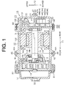
- the present invention relates to a motor-driven compressor having a compression mechanism, an electric motor, and a motor drive circuit which are disposed along the axial direction of a drive shaft of the compressor.
- the outer shell of the motor-driven compressor disclosed in the above reference includes a main housing and a front housing.
- the main housing is made of an aluminum alloy and formed in a cylindrical shape.
- the front housing is formed in the shape of a cover and connected to the front end of the main housing.
- the main housing of the motor-driven compressor accommodates therein an electric motor substantially at the center, a compression mechanism in the front, and a motor drive circuit in the rear.
- the electric motor has a stator fixed to the inner peripheral surface of the housing and a rotor mounted on the drive shaft inside of the stator.
- the compression mechanism is fixed to the inner peripheral surface of the main housing, and mounted on the drive shaft which is driven to rotate by the electric motor.
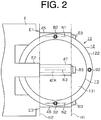
- the motor-driven compressor is formed integrally at each of the top and bottom of its outer periphery with a pair of mounting lugs for mounting the motor-driven compressor on a vehicle engine (an object to which the motor-driven compressor is to be mounted).
- the mounting lugs of each pair are spaced in the axial direction of the housing.
- Bolts fastening members are inserted through holes formed through the mounting lugs and screwed into bosses extending from the vehicle engine, so that the motor-driven compressor is mounted on the vehicle engine.
- the mounting lugs of the main housing is formed at positions outside of the compression mechanism and the electric motor along the axial direction of the main housing. Since the mounting lugs are formed integrally with the main housing, the main housing may be deformed due to differences of the clamping forces of the bolts, poor dimensional accuracy of the bosses, and the like when the mounting lugs are fastened to the bosses by the bolts. As a result, the compression mechanism and the electric motor fixed to the main housing may be displaced out of alignment, and the rotary shaft is displaced out of axial alignment. This causes unwanted noise and deterioration of the durability of bearings supporting the rotary shaft.
- JP 2006 177231 A discloses a compressor having lugs.
- This compressor has a first housing and a second housing.
- the first housing contains a motor and a compressing part having a movable scroll and a fixed scroll.
- the second housing contains a motor drive circuit.
- the first housing comprises lugs. These lugs are provided integrally with the first housing at positions of the first housing overlapping with the motor.
- the first housing 12 and the second housing 13 are fastened together by means of four second bolts B2 (only two second bolts B2 is shown in Fig. 1 ), and the first housing 12 and the third housing 14 are fastened together by means of four first bolts B1 (only two first bolts B1 is shown in Fig .1 ).
Landscapes
- Engineering & Computer Science (AREA)
- Mechanical Engineering (AREA)
- General Engineering & Computer Science (AREA)
- Applications Or Details Of Rotary Compressors (AREA)
- Compressor (AREA)
- Connection Of Motors, Electrical Generators, Mechanical Devices, And The Like (AREA)
Claims (9)
- Per Motor angetriebener Kompressor (10) mit:einem Kompressionsmechanismus (19), der ein Kühlmittelgas komprimiert;einer Drehwelle (16), die sich dreht, um den Kompressionsmechanismus (19) anzutreiben;einem Elektromotor (18), der mit der Drehwelle (16) verbunden ist;einer Motorantriebsschaltung (41) zum Antreiben des Elektromotors (18); undeiner Gehäusebaugruppe, in der der Kompressionsmechanismus (19), der Elektromotor (18) und die Motorantriebsschaltung (41) entlang der axialen Richtung der Drehwelle (16) angeordnet sind,wobei die Gehäusebaugruppe ein erstes Gehäuse (12) und ein zweites Gehäuse (13) hat,wobei das erste Gehäuse (12) verwendet wird zur Montage des Elektromotors (18) und des Kompressionsmechanismus (19) und eine erste und eine zweite Montageöse (45, 46) hat, die einstückig mit der Umfangsfläche des ersten Gehäuses (12) ausgebildet sind,wobei das zweite Gehäuse (13) mit dem ersten Gehäuse (12) verbunden ist, um die Motorantriebsschaltung (41) unterzubringen, und eine dritte Montageöse (47) hat, die einstückig mit dem zweiten Gehäuse (13) ausgebildet ist, wobei das zweite Gehäuse (13) eine zylindrische Form mit einem geschlossenen Ende hat, wobei das zweite Gehäuse einen Abdeckabschnitt (131) und einen zylindrischen Wandabschnitt (132) hat, der sich von dem gesamten Umfang des Abdeckabschnittes (131) erstreckt,dadurch gekennzeichnet, dassdie dritte Montageöse (47) mit dem Abdeckabschnitt (131) einstückig ausgebildet ist, undwobei die erste bis dritte Montageöse (45, 46, 47) an einem Montageobjekt befestigbar sind, an dem der per Motor angetriebene Kompressor (10) mittels Befestigungselementen (B1, B2, B3) montiert wird, wobei die erste und zweite Montageöse (45, 46) zwischen dem Elektromotor (18) und dem Kompressionsmechanismus (19) in der axialen Richtung der Umfangsfläche des ersten Gehäuses (12) angeordnet sind, und wobei die erste und zweite Montageöse (45, 46) einstückig mit dem ersten Gehäuse (12) an Positionen des ersten Gehäuses (12) ausgebildet sind, an denen die erste und zweite Montageöse (45, 46) nicht mit dem Elektromotor (18) und dem Kompressionsmechanismus (19) überlappen.
- Per Motor angetriebener Kompressor (10) gemäß Anspruch 1, dadurch gekennzeichnet, dass die erste bis dritte Montageöse (45, 46, 47) zu einer länglichen zylindrischen Form ausgebildet sind, die sich senkrecht zu der axialen Richtung der Drehwelle (16) erstreckt.
- Per Motor angetriebener Kompressor (10) gemäß Anspruch 1 oder 2, dadurch gekennzeichnet, dass die erste bis dritte Montageöse (45, 46, 47) ein Loch (45A, 46A, 47A) haben, das durch diese hindurch so ausgebildet ist, dass es sich senkrecht zu der axialen Richtung der Drehwelle (16) erstreckt.
- Per Motor angetriebener Kompressor (10) gemäß einem der Ansprüche 1 bis 3, dadurch gekennzeichnet, dass die dritte Montageöse (47) an einer Seite des Kompressionsmechanismus (19) angeordnet ist, die in der axialen Richtung zum ersten Gehäuse (12) entgegengesetzt ist.
- Per Motor angetriebener Kompressor (10) gemäß einem der Ansprüche 1 bis 4, dadurch gekennzeichnet, dass der Kompressionsmechanismus (19), der Elektromotor (18) und die Motorantriebsschaltung (41) in dieser Reihenfolge in der Gehäusebaugruppe angeordnet sind.
- Per Motor angetriebener Kompressor (10) gemäß einem der Ansprüche 1 bis 5, dadurch gekennzeichnet, dass das Montageobjekt, an dem der per Motor angetriebene Kompressor (10) zu montieren ist, ein Verbrennungsmotor (E) eines Hybridfahrzeugs ist.
- Per Motor angetriebener Kompressor (10) gemäß einem der Ansprüche 1 bis 6, dadurch gekennzeichnet, dass die Drehwelle (16) durch Lager (15) drehbar gestützt ist, die an der Vorderseite und an der Rückseite des ersten Gehäuses (12) angeordnet sind.
- Per Motor angetriebener Kompressor (10) gemäß einem der Ansprüche 1 bis 7, dadurch gekennzeichnet, dass die Montageöse, die mit dem ersten Gehäuse (12) einstückig ausgebildet ist, lediglich die erste und zweite Montageöse (45, 46) ist.
- Per Motor angetriebener Kompressor (10) gemäß einem der Ansprüche 1 bis 8, dadurch gekennzeichnet, dass die erste und zweite Montageöse (45, 46) an radial entgegengesetzten Seiten der Drehwelle angeordnet sind.
Applications Claiming Priority (1)
| Application Number | Priority Date | Filing Date | Title |
|---|---|---|---|
| JP2007326415A JP5018450B2 (ja) | 2007-12-18 | 2007-12-18 | 電動圧縮機 |
Publications (3)
| Publication Number | Publication Date |
|---|---|
| EP2075470A2 EP2075470A2 (de) | 2009-07-01 |
| EP2075470A3 EP2075470A3 (de) | 2015-05-06 |
| EP2075470B1 true EP2075470B1 (de) | 2017-04-19 |
Family
ID=40547917
Family Applications (1)
| Application Number | Title | Priority Date | Filing Date |
|---|---|---|---|
| EP08171965.0A Active EP2075470B1 (de) | 2007-12-18 | 2008-12-17 | Motorbetriebener Verdichter |
Country Status (4)
| Country | Link |
|---|---|
| US (1) | US8152490B2 (de) |
| EP (1) | EP2075470B1 (de) |
| JP (1) | JP5018450B2 (de) |
| CN (1) | CN101463814B (de) |
Families Citing this family (21)
| Publication number | Priority date | Publication date | Assignee | Title |
|---|---|---|---|---|
| US8777591B2 (en) * | 2010-02-16 | 2014-07-15 | Heng Sheng Precision Tech. Co., Ltd. | Electrically driven compressor system for vehicles |
| US8974197B2 (en) | 2010-02-16 | 2015-03-10 | Halla Visteon Climate Control Corporation | Compact structure for an electric compressor |
| JP5478444B2 (ja) * | 2010-09-20 | 2014-04-23 | 株式会社ヴァレオジャパン | 圧縮機 |
| JP5252020B2 (ja) * | 2011-03-25 | 2013-07-31 | 株式会社豊田自動織機 | ポンプの取付構造 |
| US9172283B2 (en) | 2012-01-17 | 2015-10-27 | Regal Beloit America, Inc. | Electric motor |
| JP5423821B2 (ja) | 2012-01-20 | 2014-02-19 | 株式会社豊田自動織機 | 電動圧縮機、及び電動圧縮機の製造方法 |
| JP5867313B2 (ja) * | 2012-06-28 | 2016-02-24 | 株式会社豊田自動織機 | 電動圧縮機 |
| JP5699994B2 (ja) | 2012-06-29 | 2015-04-15 | 株式会社豊田自動織機 | 電動圧縮機 |
| JP6203492B2 (ja) * | 2012-12-28 | 2017-09-27 | 三菱重工業株式会社 | インバータ一体型電動圧縮機 |
| JP6399398B2 (ja) * | 2014-12-18 | 2018-10-03 | パナソニックIpマネジメント株式会社 | 電動圧縮機 |
| JP2017017975A (ja) * | 2015-06-30 | 2017-01-19 | 株式会社豊田自動織機 | 電動コンプレッサ |
| JP2017180213A (ja) * | 2016-03-29 | 2017-10-05 | 株式会社豊田自動織機 | 電動圧縮機 |
| JP6658432B2 (ja) * | 2016-09-29 | 2020-03-04 | 株式会社豊田自動織機 | 車載用流体機械 |
| US10830223B2 (en) * | 2016-11-30 | 2020-11-10 | Dare Auto Inc. | Pump system |
| JP6955220B2 (ja) * | 2018-03-30 | 2021-10-27 | 株式会社豊田自動織機 | 電動圧縮機 |
| WO2020090701A1 (ja) | 2018-10-30 | 2020-05-07 | 株式会社ヴァレオジャパン | 電動圧縮機の補強構造 |
| DE102019131791B8 (de) * | 2019-11-25 | 2022-10-13 | Hanon Systems | Anordnungen zum Verbinden elektrischer Anschlüsse für eine Vorrichtung zum Antreiben eines Verdichters sowie Verfahren zum Montieren der Anordnungen und Vorrichtung zum Antreiben eines Verdichters sowie Verwendung der Vorrichtung |
| JP7817102B2 (ja) * | 2022-07-22 | 2026-02-18 | サンデン株式会社 | 電動圧縮機 |
| KR20240052379A (ko) * | 2022-10-14 | 2024-04-23 | 한온시스템 주식회사 | 전동 압축기 |
| JP2026112804A (ja) * | 2024-12-25 | 2026-07-07 | 株式会社ヴァレオジャパン | 電動圧縮機 |
| JP2026112805A (ja) * | 2024-12-25 | 2026-07-07 | 株式会社ヴァレオジャパン | 電動圧縮機 |
Citations (1)
| Publication number | Priority date | Publication date | Assignee | Title |
|---|---|---|---|---|
| US20060083649A1 (en) * | 2004-10-14 | 2006-04-20 | Matsushita Electric Industrial Co., Ltd. | Compressor |
Family Cites Families (10)
| Publication number | Priority date | Publication date | Assignee | Title |
|---|---|---|---|---|
| JP3512857B2 (ja) | 1994-06-10 | 2004-03-31 | 株式会社デンソー | スクロール型圧縮機及びそのマウント方法 |
| JP2000291557A (ja) | 1999-04-07 | 2000-10-17 | Sanden Corp | 電動式圧縮機 |
| JP4048311B2 (ja) | 2000-03-17 | 2008-02-20 | 株式会社豊田自動織機 | 電動圧縮機 |
| JP2002266766A (ja) * | 2001-03-07 | 2002-09-18 | Toyota Industries Corp | 圧縮機 |
| JP2004218585A (ja) | 2003-01-16 | 2004-08-05 | Toyota Industries Corp | 圧縮機及び圧縮機のハウジングの製造方法 |
| JP4225101B2 (ja) | 2003-04-23 | 2009-02-18 | 株式会社デンソー | 電動圧縮機 |
| JP2005155369A (ja) * | 2003-11-21 | 2005-06-16 | Toyota Industries Corp | 電動圧縮機 |
| JP2006177231A (ja) * | 2004-12-22 | 2006-07-06 | Matsushita Electric Ind Co Ltd | 電動圧縮機 |
| JP2006207391A (ja) * | 2005-01-25 | 2006-08-10 | Sanden Corp | 流体機械 |
| JP2006283694A (ja) * | 2005-04-01 | 2006-10-19 | Sanden Corp | スクロール型流体機械 |
-
2007
- 2007-12-18 JP JP2007326415A patent/JP5018450B2/ja active Active
-
2008
- 2008-12-12 US US12/334,025 patent/US8152490B2/en active Active
- 2008-12-16 CN CN200810186651.9A patent/CN101463814B/zh active Active
- 2008-12-17 EP EP08171965.0A patent/EP2075470B1/de active Active
Patent Citations (1)
| Publication number | Priority date | Publication date | Assignee | Title |
|---|---|---|---|---|
| US20060083649A1 (en) * | 2004-10-14 | 2006-04-20 | Matsushita Electric Industrial Co., Ltd. | Compressor |
Also Published As
| Publication number | Publication date |
|---|---|
| EP2075470A3 (de) | 2015-05-06 |
| JP2009150236A (ja) | 2009-07-09 |
| US8152490B2 (en) | 2012-04-10 |
| JP5018450B2 (ja) | 2012-09-05 |
| CN101463814B (zh) | 2013-05-29 |
| US20090151389A1 (en) | 2009-06-18 |
| CN101463814A (zh) | 2009-06-24 |
| EP2075470A2 (de) | 2009-07-01 |
Similar Documents
| Publication | Publication Date | Title |
|---|---|---|
| US8152490B2 (en) | Motor driven compressor | |
| EP2072754B1 (de) | Motorbetriebener Verdichter mit mehrteiligem Gehäuse | |
| US8618703B2 (en) | Motor driven compressor | |
| KR101919062B1 (ko) | 차량 탑재용 유체 기계 | |
| JP6601246B2 (ja) | 電動圧縮機 | |
| CN111120249B (zh) | 电动压缩机 | |
| CN101548105B (zh) | 电动压缩机 | |
| US7112045B2 (en) | Electric compressor | |
| JP2009250173A (ja) | 電動圧縮機 | |
| EP1382848A2 (de) | Elektrischer Kompressor und Kompressorsteuerungsanlage | |
| JP2012132435A (ja) | 空気調和機 | |
| EP2623786B1 (de) | Motorbetriebener Verdichter | |
| EP2623788B1 (de) | Motorbetriebener Verdichter | |
| JP2009150248A (ja) | インバータ一体型電動圧縮機 | |
| JP4225101B2 (ja) | 電動圧縮機 | |
| JP2025042621A (ja) | モータコネクタアセンブリを伴う電動スクロール圧縮機および電動スクロール圧縮機のためのモータコネクタアセンブリ | |
| JP5906378B2 (ja) | 電動圧縮機 | |
| JP2006177231A (ja) | 電動圧縮機 | |
| EP4138275A1 (de) | Abdeckung für ein gehäuse einer elektrischen maschine | |
| JP5931488B2 (ja) | 電動圧縮機 | |
| JP5726101B2 (ja) | 電動圧縮機のコンデンサ、電動圧縮機 | |
| JP2012021473A (ja) | 電動圧縮機 | |
| KR20240097550A (ko) | 전동 압축기 | |
| JP2013087742A (ja) | 電動圧縮機 | |
| JP2013133729A (ja) | 電動圧縮機 |
Legal Events
| Date | Code | Title | Description |
|---|---|---|---|
| PUAI | Public reference made under article 153(3) epc to a published international application that has entered the european phase |
Free format text: ORIGINAL CODE: 0009012 |
|
| 17P | Request for examination filed |
Effective date: 20081217 |
|
| AK | Designated contracting states |
Kind code of ref document: A2 Designated state(s): AT BE BG CH CY CZ DE DK EE ES FI FR GB GR HR HU IE IS IT LI LT LU LV MC MT NL NO PL PT RO SE SI SK TR |
|
| AX | Request for extension of the european patent |
Extension state: AL BA MK RS |
|
| PUAL | Search report despatched |
Free format text: ORIGINAL CODE: 0009013 |
|
| AK | Designated contracting states |
Kind code of ref document: A3 Designated state(s): AT BE BG CH CY CZ DE DK EE ES FI FR GB GR HR HU IE IS IT LI LT LU LV MC MT NL NO PL PT RO SE SI SK TR |
|
| AX | Request for extension of the european patent |
Extension state: AL BA MK RS |
|
| RIC1 | Information provided on ipc code assigned before grant |
Ipc: F04C 18/02 20060101AFI20150405BHEP Ipc: F04C 29/04 20060101ALI20150405BHEP |
|
| AKX | Designation fees paid |
Designated state(s): AT BE BG CH CY CZ DE DK EE ES FI FR GB GR HR HU IE IS IT LI LT LU LV MC MT NL NO PL PT RO SE SI SK TR |
|
| AXX | Extension fees paid |
Extension state: MK Extension state: AL Extension state: RS Extension state: BA |
|
| 17Q | First examination report despatched |
Effective date: 20160301 |
|
| GRAP | Despatch of communication of intention to grant a patent |
Free format text: ORIGINAL CODE: EPIDOSNIGR1 |
|
| INTG | Intention to grant announced |
Effective date: 20161114 |
|
| GRAS | Grant fee paid |
Free format text: ORIGINAL CODE: EPIDOSNIGR3 |
|
| GRAA | (expected) grant |
Free format text: ORIGINAL CODE: 0009210 |
|
| AK | Designated contracting states |
Kind code of ref document: B1 Designated state(s): AT BE BG CH CY CZ DE DK EE ES FI FR GB GR HR HU IE IS IT LI LT LU LV MC MT NL NO PL PT RO SE SI SK TR |
|
| REG | Reference to a national code |
Ref country code: GB Ref legal event code: FG4D |
|
| REG | Reference to a national code |
Ref country code: CH Ref legal event code: EP |
|
| REG | Reference to a national code |
Ref country code: AT Ref legal event code: REF Ref document number: 886248 Country of ref document: AT Kind code of ref document: T Effective date: 20170515 |
|
| REG | Reference to a national code |
Ref country code: IE Ref legal event code: FG4D |
|
| REG | Reference to a national code |
Ref country code: DE Ref legal event code: R096 Ref document number: 602008049808 Country of ref document: DE |
|
| REG | Reference to a national code |
Ref country code: NL Ref legal event code: MP Effective date: 20170419 |
|
| REG | Reference to a national code |
Ref country code: LT Ref legal event code: MG4D |
|
| REG | Reference to a national code |
Ref country code: AT Ref legal event code: MK05 Ref document number: 886248 Country of ref document: AT Kind code of ref document: T Effective date: 20170419 |
|
| PG25 | Lapsed in a contracting state [announced via postgrant information from national office to epo] |
Ref country code: NL Free format text: LAPSE BECAUSE OF FAILURE TO SUBMIT A TRANSLATION OF THE DESCRIPTION OR TO PAY THE FEE WITHIN THE PRESCRIBED TIME-LIMIT Effective date: 20170419 |
|
| PG25 | Lapsed in a contracting state [announced via postgrant information from national office to epo] |
Ref country code: GR Free format text: LAPSE BECAUSE OF FAILURE TO SUBMIT A TRANSLATION OF THE DESCRIPTION OR TO PAY THE FEE WITHIN THE PRESCRIBED TIME-LIMIT Effective date: 20170720 Ref country code: LT Free format text: LAPSE BECAUSE OF FAILURE TO SUBMIT A TRANSLATION OF THE DESCRIPTION OR TO PAY THE FEE WITHIN THE PRESCRIBED TIME-LIMIT Effective date: 20170419 Ref country code: ES Free format text: LAPSE BECAUSE OF FAILURE TO SUBMIT A TRANSLATION OF THE DESCRIPTION OR TO PAY THE FEE WITHIN THE PRESCRIBED TIME-LIMIT Effective date: 20170419 Ref country code: NO Free format text: LAPSE BECAUSE OF FAILURE TO SUBMIT A TRANSLATION OF THE DESCRIPTION OR TO PAY THE FEE WITHIN THE PRESCRIBED TIME-LIMIT Effective date: 20170719 Ref country code: FI Free format text: LAPSE BECAUSE OF FAILURE TO SUBMIT A TRANSLATION OF THE DESCRIPTION OR TO PAY THE FEE WITHIN THE PRESCRIBED TIME-LIMIT Effective date: 20170419 Ref country code: HR Free format text: LAPSE BECAUSE OF FAILURE TO SUBMIT A TRANSLATION OF THE DESCRIPTION OR TO PAY THE FEE WITHIN THE PRESCRIBED TIME-LIMIT Effective date: 20170419 Ref country code: AT Free format text: LAPSE BECAUSE OF FAILURE TO SUBMIT A TRANSLATION OF THE DESCRIPTION OR TO PAY THE FEE WITHIN THE PRESCRIBED TIME-LIMIT Effective date: 20170419 |
|
| PG25 | Lapsed in a contracting state [announced via postgrant information from national office to epo] |
Ref country code: IS Free format text: LAPSE BECAUSE OF FAILURE TO SUBMIT A TRANSLATION OF THE DESCRIPTION OR TO PAY THE FEE WITHIN THE PRESCRIBED TIME-LIMIT Effective date: 20170819 Ref country code: LV Free format text: LAPSE BECAUSE OF FAILURE TO SUBMIT A TRANSLATION OF THE DESCRIPTION OR TO PAY THE FEE WITHIN THE PRESCRIBED TIME-LIMIT Effective date: 20170419 Ref country code: SE Free format text: LAPSE BECAUSE OF FAILURE TO SUBMIT A TRANSLATION OF THE DESCRIPTION OR TO PAY THE FEE WITHIN THE PRESCRIBED TIME-LIMIT Effective date: 20170419 Ref country code: BG Free format text: LAPSE BECAUSE OF FAILURE TO SUBMIT A TRANSLATION OF THE DESCRIPTION OR TO PAY THE FEE WITHIN THE PRESCRIBED TIME-LIMIT Effective date: 20170719 Ref country code: PL Free format text: LAPSE BECAUSE OF FAILURE TO SUBMIT A TRANSLATION OF THE DESCRIPTION OR TO PAY THE FEE WITHIN THE PRESCRIBED TIME-LIMIT Effective date: 20170419 |
|
| REG | Reference to a national code |
Ref country code: FR Ref legal event code: PLFP Year of fee payment: 10 |
|
| REG | Reference to a national code |
Ref country code: DE Ref legal event code: R097 Ref document number: 602008049808 Country of ref document: DE |
|
| PG25 | Lapsed in a contracting state [announced via postgrant information from national office to epo] |
Ref country code: DK Free format text: LAPSE BECAUSE OF FAILURE TO SUBMIT A TRANSLATION OF THE DESCRIPTION OR TO PAY THE FEE WITHIN THE PRESCRIBED TIME-LIMIT Effective date: 20170419 Ref country code: EE Free format text: LAPSE BECAUSE OF FAILURE TO SUBMIT A TRANSLATION OF THE DESCRIPTION OR TO PAY THE FEE WITHIN THE PRESCRIBED TIME-LIMIT Effective date: 20170419 Ref country code: SK Free format text: LAPSE BECAUSE OF FAILURE TO SUBMIT A TRANSLATION OF THE DESCRIPTION OR TO PAY THE FEE WITHIN THE PRESCRIBED TIME-LIMIT Effective date: 20170419 Ref country code: RO Free format text: LAPSE BECAUSE OF FAILURE TO SUBMIT A TRANSLATION OF THE DESCRIPTION OR TO PAY THE FEE WITHIN THE PRESCRIBED TIME-LIMIT Effective date: 20170419 Ref country code: CZ Free format text: LAPSE BECAUSE OF FAILURE TO SUBMIT A TRANSLATION OF THE DESCRIPTION OR TO PAY THE FEE WITHIN THE PRESCRIBED TIME-LIMIT Effective date: 20170419 |
|
| PLBE | No opposition filed within time limit |
Free format text: ORIGINAL CODE: 0009261 |
|
| STAA | Information on the status of an ep patent application or granted ep patent |
Free format text: STATUS: NO OPPOSITION FILED WITHIN TIME LIMIT |
|
| 26N | No opposition filed |
Effective date: 20180122 |
|
| PG25 | Lapsed in a contracting state [announced via postgrant information from national office to epo] |
Ref country code: SI Free format text: LAPSE BECAUSE OF FAILURE TO SUBMIT A TRANSLATION OF THE DESCRIPTION OR TO PAY THE FEE WITHIN THE PRESCRIBED TIME-LIMIT Effective date: 20170419 |
|
| REG | Reference to a national code |
Ref country code: CH Ref legal event code: PL |
|
| GBPC | Gb: european patent ceased through non-payment of renewal fee |
Effective date: 20171217 |
|
| REG | Reference to a national code |
Ref country code: IE Ref legal event code: MM4A |
|
| PG25 | Lapsed in a contracting state [announced via postgrant information from national office to epo] |
Ref country code: LU Free format text: LAPSE BECAUSE OF NON-PAYMENT OF DUE FEES Effective date: 20171217 Ref country code: MT Free format text: LAPSE BECAUSE OF NON-PAYMENT OF DUE FEES Effective date: 20171217 |
|
| REG | Reference to a national code |
Ref country code: BE Ref legal event code: MM Effective date: 20171231 |
|
| PG25 | Lapsed in a contracting state [announced via postgrant information from national office to epo] |
Ref country code: IE Free format text: LAPSE BECAUSE OF NON-PAYMENT OF DUE FEES Effective date: 20171217 |
|
| PG25 | Lapsed in a contracting state [announced via postgrant information from national office to epo] |
Ref country code: BE Free format text: LAPSE BECAUSE OF NON-PAYMENT OF DUE FEES Effective date: 20171231 Ref country code: CH Free format text: LAPSE BECAUSE OF NON-PAYMENT OF DUE FEES Effective date: 20171231 Ref country code: LI Free format text: LAPSE BECAUSE OF NON-PAYMENT OF DUE FEES Effective date: 20171231 Ref country code: GB Free format text: LAPSE BECAUSE OF NON-PAYMENT OF DUE FEES Effective date: 20171217 |
|
| PG25 | Lapsed in a contracting state [announced via postgrant information from national office to epo] |
Ref country code: MC Free format text: LAPSE BECAUSE OF FAILURE TO SUBMIT A TRANSLATION OF THE DESCRIPTION OR TO PAY THE FEE WITHIN THE PRESCRIBED TIME-LIMIT Effective date: 20170419 Ref country code: HU Free format text: LAPSE BECAUSE OF FAILURE TO SUBMIT A TRANSLATION OF THE DESCRIPTION OR TO PAY THE FEE WITHIN THE PRESCRIBED TIME-LIMIT; INVALID AB INITIO Effective date: 20081217 |
|
| PG25 | Lapsed in a contracting state [announced via postgrant information from national office to epo] |
Ref country code: CY Free format text: LAPSE BECAUSE OF NON-PAYMENT OF DUE FEES Effective date: 20170419 |
|
| PG25 | Lapsed in a contracting state [announced via postgrant information from national office to epo] |
Ref country code: TR Free format text: LAPSE BECAUSE OF FAILURE TO SUBMIT A TRANSLATION OF THE DESCRIPTION OR TO PAY THE FEE WITHIN THE PRESCRIBED TIME-LIMIT Effective date: 20170419 |
|
| PG25 | Lapsed in a contracting state [announced via postgrant information from national office to epo] |
Ref country code: PT Free format text: LAPSE BECAUSE OF FAILURE TO SUBMIT A TRANSLATION OF THE DESCRIPTION OR TO PAY THE FEE WITHIN THE PRESCRIBED TIME-LIMIT Effective date: 20170419 |
|
| P01 | Opt-out of the competence of the unified patent court (upc) registered |
Effective date: 20230519 |
|
| PGFP | Annual fee paid to national office [announced via postgrant information from national office to epo] |
Ref country code: DE Payment date: 20251028 Year of fee payment: 18 |
|
| PGFP | Annual fee paid to national office [announced via postgrant information from national office to epo] |
Ref country code: IT Payment date: 20251121 Year of fee payment: 18 |
|
| PGFP | Annual fee paid to national office [announced via postgrant information from national office to epo] |
Ref country code: FR Payment date: 20251110 Year of fee payment: 18 |