EP2075476A2 - Befestigungssystem, insbesondere für metallische Bauteile - Google Patents
Befestigungssystem, insbesondere für metallische Bauteile Download PDFInfo
- Publication number
- EP2075476A2 EP2075476A2 EP08020676A EP08020676A EP2075476A2 EP 2075476 A2 EP2075476 A2 EP 2075476A2 EP 08020676 A EP08020676 A EP 08020676A EP 08020676 A EP08020676 A EP 08020676A EP 2075476 A2 EP2075476 A2 EP 2075476A2
- Authority
- EP
- European Patent Office
- Prior art keywords
- base plate
- plate
- counter
- hooking
- pairs
- Prior art date
- Legal status (The legal status is an assumption and is not a legal conclusion. Google has not performed a legal analysis and makes no representation as to the accuracy of the status listed.)
- Granted
Links
- 238000005452 bending Methods 0.000 claims abstract description 17
- 235000001674 Agaricus brunnescens Nutrition 0.000 claims description 2
- 230000013011 mating Effects 0.000 claims description 2
- 230000007704 transition Effects 0.000 claims description 2
- 238000004873 anchoring Methods 0.000 description 11
- 239000000853 adhesive Substances 0.000 description 6
- 230000001070 adhesive effect Effects 0.000 description 6
- 239000000463 material Substances 0.000 description 3
- 229910001220 stainless steel Inorganic materials 0.000 description 3
- 239000007769 metal material Substances 0.000 description 2
- 238000004080 punching Methods 0.000 description 2
- 239000010935 stainless steel Substances 0.000 description 2
- 229910000851 Alloy steel Inorganic materials 0.000 description 1
- 229910000639 Spring steel Inorganic materials 0.000 description 1
- 239000003575 carbonaceous material Substances 0.000 description 1
- 230000000295 complement effect Effects 0.000 description 1
- 238000005520 cutting process Methods 0.000 description 1
- 238000009434 installation Methods 0.000 description 1
- 239000011810 insulating material Substances 0.000 description 1
- 239000012774 insulation material Substances 0.000 description 1
- 230000001788 irregular Effects 0.000 description 1
- 238000004519 manufacturing process Methods 0.000 description 1
- 229910001092 metal group alloy Inorganic materials 0.000 description 1
- 238000000034 method Methods 0.000 description 1
- 230000002441 reversible effect Effects 0.000 description 1
- IHQKEDIOMGYHEB-UHFFFAOYSA-M sodium dimethylarsinate Chemical class [Na+].C[As](C)([O-])=O IHQKEDIOMGYHEB-UHFFFAOYSA-M 0.000 description 1
- 230000003068 static effect Effects 0.000 description 1
- 210000002268 wool Anatomy 0.000 description 1
Images

Classifications
-
- F—MECHANICAL ENGINEERING; LIGHTING; HEATING; WEAPONS; BLASTING
- F16—ENGINEERING ELEMENTS AND UNITS; GENERAL MEASURES FOR PRODUCING AND MAINTAINING EFFECTIVE FUNCTIONING OF MACHINES OR INSTALLATIONS; THERMAL INSULATION IN GENERAL
- F16B—DEVICES FOR FASTENING OR SECURING CONSTRUCTIONAL ELEMENTS OR MACHINE PARTS TOGETHER, e.g. NAILS, BOLTS, CIRCLIPS, CLAMPS, CLIPS OR WEDGES; JOINTS OR JOINTING
- F16B5/00—Joining sheets or plates, e.g. panels, to one another or to strips or bars parallel to them
- F16B5/07—Joining sheets or plates, e.g. panels, to one another or to strips or bars parallel to them by means of multiple interengaging protrusions on the surfaces, e.g. hooks, coils
Definitions
- the invention relates to a fastening system, in particular for metallic components, with a metallic base plate, cut out of the hooking elements and are raised from the plane of the base plate by spaced parallel bending lines that hook pairs are formed, each having two Verhakungs institute that, to each other formed mirror-inverted, facing each other and each interlocking element Verhakungsr selected for cooperation with a mating counterpart has.
- Fastening systems of this type are known, cf. DE 10 2006 015 145 A1 .
- these fastening systems make it possible to use the advantages of the proven plastic-based adhesive fastening systems, as they have found for a variety of applications, even in those applications where plastic adhesive closures are not applicable, for example, due to lack of temperature stability , mechanical strength and the like.
- temperature-resistant metal alloys such as stainless steel
- existing Verhakungs such metallic adhesive closures can also be used in areas where high thermal and mechanical stresses occur. This allow such fastening systems a quick and easy installation of third party components without the need for additional support devices and their operation would be required by special tools.
- the invention has the object of providing a fastening system which is optimized in terms of the relevant operating behavior in the manner of a metallic adhesive closure.
- a significant feature of the invention is accordingly that the entanglement is done in a special way so that an associated pair of hooks is provided for each pair of hooks of the base plate, which is provided on a serving as a counterpart counter-plate, wherein the pairs of hooks on the counter-plate according to the pairs of hooks the base plate are designed, apart from the fact that in the cooperating pairs of hooks each bending lines are offset by 90 degrees to each other, which means that the actual Verhakungseingriff takes place in each case by rectangular overlapping the Verhakungsr selected a pair through the Verhakungsr selected the associated pair.
- This design makes it possible to optimally calibrate the system in terms of holding force and release force by With regard to the dimensioning and orientation of the Verhakungsr selected the properties of the respective metallic material are taken into account, in particular the elasticity properties.
- the pairs of hooks are arranged on the base plate and counter-plate in a corresponding pattern in mutually parallel rows, wherein the bending lines are rotated in each case by 90 degrees to each other in successive pairs of hooks in the rows.
- the hooking elements are planar with a connected to the bending line with the base plate or counter-plate foot part and an adjoining headboard, which is widened relative to the foot and adjacent to this education on both sides projecting Verhakungsr only.
- the size of the holding and releasing force can be adjusted to a desired optimal value by the Verhakungsr selected to the outer sides of the Verhakungs comprise out towards the plane of the base plate or counter-plate inclined upward.
- the angle of inclination holding and releasing force can be suitably adapted to the particular application.
- the arrangement can also be made such that the hooking elements of each pair of hooks starting from the base plate or counterplate are divergent starting from one another.
- the arrangement is such that the head portion has a rounded upper end edge connecting the ends of the hooking edges to form a mushroom shape of the hooking elements.
- the Verhakungseingriff can be easily and safely made, because when bringing together the hook pairs, the rounded end edges of the head parts are slidably guided together, so that self-centering when overflowing the ends of Verhakungsr selected whose Verhakungsübergriff comes about.
- Velcro ® -Haftverêtn made of plastic materials usual, the shutter repeatedly open and close, so that it equipped third components in case of failure on site are readily interchangeable.
- Fig. 1-3 is a flat base plate made of a heat-resistant steel alloy, in particular stainless or spring steel, designated 1, which forms part of the fastening system according to the invention.
- a regular pattern with parallel, even rows 3 are in the base plate 1 Verhakungsetti 5, which are not all figured in the figures, cut out and raised from the plane of the base plate 1. How out Fig.
- each row 3 pairs of hooks are formed, namely in such a way that two Verhakungs institute 5, which are mirror images of the same shape to bend lines 7, which run parallel to each other in each pair at a distance parallel and in the drawing also not all are quantified, are placed high, so that the hooking elements 5 of each pair are facing each other with their broadsides.
- each of the bending lines 7 are offset from one pair to another pair by 90 degrees in the successive pairs in the rows 3 hook pairs.
- each pair of hooks starting from the bending line 7 on the base plate 1, slightly divergently inclined towards each other, so that at each pair of hooks the head parts 9 (in the figures not all quantified) have a greater distance from each other than the Feet 11 (also not all quantified) each pair of hooks.
- the Fig. 4 shows the example of two hooking hook pairs with each other in the details of the design of the Verhakungs institute 5. It follows that starting from the respective bending lines 7, the foot parts 11 with straight side edges 13 which extend divergent to the head part 9 towards each other, so that the foot part 11 widens against the head part 9 out. At the end of the page margins 13, so at the transition between the foot part 11 and the head part 9, projecting anchoring edges 15 are formed on both sides. A part of a circular arc forming end edge 17 of the mushroom-like widened head portion 9 connects the outer ends 19 of the anchoring edges 15.
- ⁇ the angle of inclination, with which the hooking elements 5 of each hook pair diverge upwards to each other denoted by ⁇ .
- the anchoring edges 15 of each hooking element 5 in the present example are not parallel to the plane of the base plate 1, but slightly inclined upward (ie away from the bending line 7) slightly inclined, said angle in Fig. 4 is denoted by ⁇ .
- Fig. 2 and 3 This also corresponds to the counterpart provided for the anchoring to the base plate 1 in the form of a counter plate 21.
- the counter-plate 21 from the in Fig. 2 shown position in the hooking position of Fig. 3 a mutual entanglement in such a way that each hook pair of a plate 1 hooked with an associated pair of hooks of the other plate 21, as shown in FIG Fig. 4 is illustrated in detail.
- the prerequisite for this is that the plates 1 and 21 are brought together in such an orientation that when cooperating pairs of hooks, the bending lines 7 are perpendicular to each other, as in Fig. 4 is shown in detail.
- the entanglement takes place when the plates 1 and 21 are approximated to the hook pairs self-centering in such a way that the approach of one pair of hooks to the other pair of hooks, the end edges 17 of the merged head parts 11 are slidably guided, whereby the Divergence of the hooking elements 5 increases, that is, the angle ⁇ is increased until the end edges 17 of the head parts 9 respectively overflow the ends 19 of the anchoring edges 15, so that the head parts 11 resiliently snap inwardly against the anchoring edges 15, so that there is a right-angled overgrip.
- the head parts 9 of the anchoring elements 5 are outwardly controlled to increase the divergence (the angle ⁇ ) until the ends 19 of the cooperating one Anchoring edges 15 are disengaged.
- base plate 1 and / or counter-plate 21 could have other outlines instead of the wide rectangular shape shown, for example, ribbon or strip shape. Such shapes could be advantageous when base plate 1 and counter plate 21 are to be attached to components having irregular surface shape. Also base plate 1 and counter-plate 21 could be curved complementary to each other to accommodate curved components to be fixed to each other.
- the individual pairs of hooks can be obtained preferably by a punching or cutting process of a thin platinum-shaped sheet material and as sheet metal material is in particular selected one which is provided with a predefinable spring elasticity in order to slightly pivot the wing-like hook pairs in position relative to the bending line can. This results in the reversible Release and closing process by the interlocking and separating the adhesive closure parts. If the base plate is fixed to a component which may be arranged stationary, a correspondingly formed counter plate connected to a third component can be releasably connected to the base plate via the pairs of closure parts, so that in the event of failure, the respective third component is replaceable. Such a variety of technical applications are conceivable, especially in places where high temperatures can occur.
- the board thickness is preferably selected in the range of 0.05-3 mm, and said angles ⁇ and ⁇ are in the range of 2 to 45 degrees, more preferably in ranges of 15 degrees.
- an insulating material can be introduced, for example in the form of stainless steel wool, carbon materials, also in granular form, and the like.
- the combination of base plate 1 with counter-holding plate 21 can also be used as a high-temperature-resistant insulating component.
Landscapes
- Engineering & Computer Science (AREA)
- General Engineering & Computer Science (AREA)
- Mechanical Engineering (AREA)
- Connection Of Plates (AREA)
- Hooks, Suction Cups, And Attachment By Adhesive Means (AREA)
Abstract
Description
- Die Erfindung betrifft ein Befestigungssystem, insbesondere für metallische Bauteile, mit einer metallischen Grundplatte, aus der Verhakungselemente derart ausgeschnitten und aus der Ebene der Grundplatte um im Abstand voneinander parallele Biegelinien hochgestellt sind, dass Hakenpaare gebildet sind, die jedes zwei Verhakungselemente aufweisen, die, zueinander spiegelbildlich geformt, einander gegenüberliegen und jedes Verhakungselement Verhakungsränder für die Zusammenwirkung mit einem zu verankernden Gegenstück aufweist.
- Befestigungssysteme dieser Art sind bekannt, vgl.
DE 10 2006 015 145 A1 . Als eine Art metallischer Haftverschluss ermöglichen es diese Befestigungssysteme, die Vorteile der bewährten Haftverschlusssysteme auf Kunststoffbasis, wie sie für eine Vielzahl von Anwendungsgebieten weiteste Verbreitung gefunden haben, auch in solchen Anwendungsfällen zu nutzen, bei denen Kunststoff-Haftverschlüsse nicht einsetzbar sind, beispielsweise wegen fehlender Temperaturstabilität, mechanischer Festigkeit und dergleichen. Bei aus temperaturfesten Metalllegierungen, etwa Edelstahl, bestehenden Verhakungselementen lassen sich derartige metallische Haftverschlüsse auch in Bereichen einsetzen, bei denen hohe thermische und mechanische Belastungen auftreten. Hierbei ermöglichen derartige Befestigungssysteme eine schnelle und einfache Montage von Drittbauteilen ohne dass ein Bedarf an zusätzlichen Halterungsvorrichtungen und deren Betätigung durch spezielle Werkzeuge erforderlich wäre. - An das Betriebsverhalten derartiger Befestigungssysteme sind insbesondere zwei Anforderungen zu stellen. Zum einen muss eine ausreichend große Haltekraft vorhanden sein, um betreffende Bauteile gegen auftretende statische oder dynamische (Schwingungen) Lastkräfte zu sichern. Zum anderen soll die Haltekraft einen vorgegebenen Wert nicht übersteigen, damit ein Lösen der Verhakung für Demontage oder Ersatz von Bauteilen bei Bedarf möglich ist.
- Die Erfindung stellt sich im Hinblick auf diese Problematik die Aufgabe, ein hinsichtlich des diesbezüglichen Betriebsverhaltens optimiertes Befestigungssystem in der Art eines metallischen Haftverschlusses zur Verfügung zu stellen.
- Erfindungsgemäß ist diese Aufgabe durch ein Befestigungssystem gelöst, das die Merkmale des Patentanspruches 1 in seiner Gesamtheit aufweist.
- Eine wesentliche Besonderheit der Erfindung besteht demgemäß darin, dass die Verhakung in spezieller Weise so erfolgt, dass für jedes Hakenpaar der Grundplatte ein zugeordnetes Hakenpaar vorgesehen ist, das an einer als Gegenstück dienenden Gegenplatte vorgesehen ist, wobei die Hakenpaare an der Gegenplatte entsprechend den Hakenpaaren an der Grundplatte gestaltet sind, abgesehen davon, dass bei den zusammenwirkenden Hakenpaaren jeweils die Biegelinien um 90 Grad zueinander versetzt sind, was bedeutet, dass der eigentliche Verhakungseingriff jeweils durch rechtwinkliges Übergreifen der Verhakungsränder eines Paares durch die Verhakungsränder des zugeordneten Paares erfolgt. Diese Gestaltung ermöglicht es, das System hinsichtlich Haltekraft und Lösekraft optimal zu kalibrieren, indem bezüglich der Dimensionierung und Orientierung der Verhakungsränder die Eigenschaften des betreffenden metallischen Werkstoffes in Rechnung gesetzt werden, insbesondere die Elastizitätseigenschaften.
- Vorzugsweise sind die Hakenpaare an Grundplatte und Gegenplatte in einem entsprechenden Muster in zueinander parallelen Reihen angeordnet, wobei die Biegelinien bei in den Reihen aufeinanderfolgenden Hakenpaaren jeweils um 90 Grad zueinander verdreht sind.
- Bei besonders vorteilhaften Ausführungsbeispielen sind die Verhakungselemente ebenflächig mit einem an der Biegelinie mit der Grundplatte oder Gegenplatte verbundenen Fußteil und einem sich daran anschließenden Kopfteil gestaltet, das gegenüber dem Fußteil verbreitert ist und an dieses unter Bildung beidseits auskragender Verhakungsränder angrenzt.
- In vorteilhafter Weise läßt sich die Größe der Halte- und Lösekraft auf einen gewünschten Optimalwert einstellen, indem die Verhakungsränder zu den Außenseiten der Verhakungselemente hin gegenüber der Ebene der Grundplatte oder Gegenplatte nach oben geneigt verlaufen. Durch die Wahl des Neigungswinkels lassen sich Halte- und Lösekraft in geeigneter Weise dem jeweiligen Einsatzzweck anpassen.
- Die Anordnung kann auch so getroffen sein, dass die Verhakungselemente jedes Hakenpaares von Grundplatte oder Gegenplatte ausgehend zueinander divergierend verlaufen. Durch die Wahl des diesbezüglichen Neigungswinkels gegenüber der Plattenebene ist die Größe der Halte- und Lösekraft ebenfalls beeinflußbar.
- Vorzugsweise ist die Anordnung so getroffen, dass das Kopfteil zur Bildung einer Pilzform der Verhakungselemente einen abgerundeten oberen Endrand aufweist, der die Enden der Verhakungsränder verbindet. Solche Ausführungsbeispiele zeichnen sich dadurch aus, dass der Verhakungseingriff einfach und sicher hergestellt werden kann, weil beim Zusammenbringen der Hakenpaare die gerundeten Endränder der Kopfteile aneinander gleitend geführt sind, so dass selbstzentrierend beim Überlaufen der Enden der Verhakungsränder deren Verhakungsübergriff zustande kommt. Im übrigen läßt sich wie bei Kletten®-Haftverschlüssen aus Kunststoffmaterialien üblich, der Verschluß immer wieder öffnen und schließen, so dass damit ausgestattete Drittbauteile im Versagensfall vor Ort ohne weiteres austauschbar sind.
- Nachstehend ist die Erfindung anhand eines in der Zeichnung dargestellten Ausführungsbeispieles im Einzelnen erläutert. Es zeigen:
-
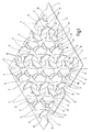
Fig. 1 eine zur Verdeutlichung des Erfindungsprinzips in leicht vergrößertem Maßstab gezeichnete perspektivische Schrägansicht eines Abschnitts einer metallischen Grundplatte mit darin ausgeschnittenen und hochgestellten Verhakungselementen eines Ausführungsbeispieles des erfindungsgemäßen Befestigungssystems; -
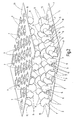
Fig. 2 eine derFig. 1 ähnliche perspektivische Schrägansicht, wobei sowohl die Grundplatte als auch eine zugeordnete Gegenplatte mit Verhakungselementen gemäß dem Ausführungsbeispiel der Erfindung im Zustand von der gegenseitigen Verhakung dargestellt sind; -
Fig. 3 eine derFig. 2 ähnliche perspektivische Schrägansicht, wobei der Zustand der gegenseitigen Verhakung dargestellt ist, und -
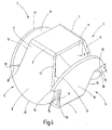
Fig. 4 eine in übertrieben großem Maßstab gezeichnete perspektivische Schrägansicht lediglich zweier miteinander im Verhakungseingriff befindlicher Hakenpaare des Ausführungsbeispieles. - In den
Fig. 1 - 3 ist eine ebene Grundplatte aus einer wärmebeständigen Stahllegierung, insbesondere Edel- oder Federstahl, mit 1 bezeichnet, die Bestandteil des erfindungsgemäßen Befestigungssystemes bildet. In einem regelmäßigen Muster mit zueinander parallelen, geraden Reihen 3 (Fig. 1 ) sind in der Grundplatte 1 Verhakungselemente 5, die in den Fig. nicht sämtliche beziffert sind, ausgeschnitten und aus der Ebene der Grundplatte 1 hochgestellt. Wie ausFig. 1 deutlich zu ersehen ist, sind in den Reihen 3 aufeinanderfolgend jeweils Hakenpaare gebildet, nämlich in der Weise, dass zwei Verhakungselemente 5, die zueinander spiegelbildlich gleich geformt sind, um Biegelinien 7, die bei jedem Paar im Abstand zueinander parallel verlaufen und in der Zeichnung ebenfalls nicht sämtliche beziffert sind, hochgestellt sind, so dass die Verhakungselemente 5 jedes Paares mit ihren Breitseiten einander zugekehrt sind. Wie ebenfalls ausFig. 1 entnehmbar ist, sind bei den in den Reihen 3 aufeinanderfolgenden Hakenpaaren jeweils die Biegelinien 7 von einem Paar zum anderen Paar um 90 Grad versetzt. Außerdem sind die Verhakungselemente 5 jedes Hakenpaares, von der Biegelinie 7 an der Grundplatte 1 ausgehend, nach oben hin zueinander leicht divergierend geneigt, so dass bei jedem Hakenpaar die Kopfteile 9 (in den Fig. nicht sämtliche beziffert) voneinander einen größeren Abstand besitzen als die Fußteile 11 (ebenfalls nicht sämtliche beziffert) jedes Hakenpaares. - Die
Fig. 4 zeigt am Beispiel zweier miteinander in Verhakungseingriff befindlicher Hakenpaare die Einzelheiten der Formgestaltung der Verhakungselemente 5. Hieraus ist ersichtlich, dass von den jeweiligen Biegelinien 7 ausgehend die Fußteile 11 mit geradlinigen Seitenrändern 13, die zueinander divergierend zum Kopfteil 9 hin verlaufen, so dass sich das Fußteil 11 gegen das Kopfteil 9 hin verbreitert. Am Ende der Seitenränder 13, also am Übergang zwischen Fußteil 11 und Kopfteil 9, sind beidseits auskragende Verankerungsränder 15 gebildet. Ein den Teil eines Kreisbogens bildender Endrand 17 des pilzkopfartig erweiterten Kopfteiles 9 verbindet die äußeren Enden 19 der Verankerungsränder 15. InFig. 4 ist der Neigungswinkel, mit dem die Verhakungselemente 5 jedes Hakenpaares nach oben hin zueinander divergieren mit β bezeichnet. Wie bereits erwähnt, verlaufen die Verankerungsränder 15 jedes Verhakungselementes 5 beim vorliegenden Beispiel nicht parallel zur Ebene der Grundplatte 1, sondern leicht schräg nach oben (also von der Biegelinie 7 weg) leicht geneigt, wobei dieser Winkel inFig. 4 mit α bezeichnet ist. -
Fig. 2 und3 zeigen auch das für die Verankerung an der Grundplatte 1 vorgesehene Gegenstück in Form einer Gegenplatte 21. Diese entspricht in sämtlichen Einzelheiten der Grundplatte 1, was bedeutet, dass sie in vorteilhafter Weise mittels der gleichen Fertigungseinrichtung (sowohl Stanzen als auch Hochstel len) hergestellt werden kann. Entsprechend der gleichartigen Anordnung der Hakenpaare erfolgt beim Zusammenfahren, wenn also die Gegenplatte 21 aus der inFig. 2 gezeigten Position in die Verhakungsposition vonFig. 3 gebracht wird, eine gegenseitige Verhakung in der Weise, dass jedes Hakenpaar der einen Platte 1 mit einem zugeordneten Hakenpaar der anderen Platte 21 verhakt, wie dies inFig. 4 in Einzeldarstellung verdeutlicht ist. Voraussetzung hierfür ist, dass die Platten 1 und 21 in solcher Orientierung miteinander zusammengebracht werden, dass bei zusammenwirkenden Hakenpaaren die Biegelinien 7 zueinander senkrecht verlaufen, wie dies inFig. 4 im Einzelnen dargestellt ist. - Bei solcher Orientierung erfolgt die Verhakung, wenn die Platten 1 und 21 aneinander angenähert werden, an den Hakenpaaren selbstzentrierend in der Weise, dass bei der Annäherung des einen Hakenpaares an das andere Hakenpaar die Endränder 17 der zusammengeführten Kopfteile 11 aufeinander gleitend geführt sind, wodurch die Divergenz der Verhakungselemente 5 zunimmt, d. h. der Winkel β vergrößert wird, bis die Endränder 17 der Kopfteile 9 jeweils die Enden 19 der Verankerungsränder 15 überlaufen, so dass die Kopfteile 11 elastisch nach einwärts an den Verankerungsrändern 15 einschnappen, so dass sich an diesen ein rechtwinkliger Übergriff ergibt.
- Da andererseits die Verankerungsränder 15 um den Winkel α geneigt verlaufen, werden, wenn eine die Haltekraft übersteigende Lösekraft aufgebracht wird, die Kopfteile 9 der Verankerungselemente 5 nach außen gesteuert, um die Divergenz (den Winkel β) zu erhöhen, bis die Enden 19 der zusammenwirkenden Verankerungsränder 15 miteinander außer Eingriff kommen. Durch Wahl der Winkel α und β und in Entsprechung zu den Elastizitätseigenschaften des die Verhakungselemente 5 bildenden Werkstoffes läßt sich somit eine gewünschte Stärke der Verankerungskraft, die für eine gewolltes Lösen der Verankerung überwunden werden muss, einstellen. Das erfindungsgemäße Befestigungssystem ist somit optimal an jeweils vorherrschende Einsatzbedingungen anpassbar.
- Es versteht sich, dass Grundplatte 1 und/oder Gegenplatte 21 anstelle der gezeigten breitflächigen Rechteckform andere Umrisse aufweisen könnten, beispielsweise Band- oder Streifenform. Solche Formen könnten von Vorteil sein, wenn Grundplatte 1 und Gegenplatte 21 an Bauteilen mit unregelmäßiger Oberflächengestalt anzubringen sind. Auch könnten Grundplatte 1 und Gegenplatte 21 zur Anpassung an gewölbte, zu fixierende Bauteile zueinander komplementär gewölbt sein.
- Die einzelnen Hakenpaare lassen sich vorzugsweise durch einen Stanz- oder Schneidvorgang aus einem dünnen platinenförmigen Blechwerkstoff gewinnen und als Blechmaterial wird insbesondere ein solches ausgewählt, das mit einer vorgebbaren Federelastizität versehen ist, um dergestalt die flügelartig ausgebildeten Hakenpaare in ihrer Position gegenüber der Biegelinie geringfügig verschwenken zu können. Hieraus resultiert der reversible Löse- und Schließvorgang durch das Ineinandergreifen und Auseinanderbringen der Haftverschlußteile. Sofern die Grundplatte an einem Bauteil festgelegt ist, das stationär angeordnet sein kann, läßt sich eine entsprechend ausgebildete Gegenplatte mit einem Drittbauteil verbunden über die Paare an Verschlußteilen lösbar mit der Grundplatte verbinden, so dass dergestalt im Versagensfall das jeweilige Drittbauteil austauschbar ist. Dergestalt sind eine Vielzahl an technischen Anwendungsfällen denkbar, insbesondere an Orten wo hohe Temperaturen auftreten können.
- Die Platinenstärke wird vorzugsweise im Bereich von 0,05 - 3mm gewählt und die genannten Winkel α und β liegen im Bereich von 2 bis 45 Grad, besonders bevorzugt in Bereichen um 15 Grad. Sind, wie dies die
Fig. 4 zeigt, die benachbarten Hakenpaare von Grundplatte 1 und Gegenplatte 21 miteinander in Eingriff, entstehen geschlossene kastenförmige Räume, in denen entsprechend gekammert zusätzlich ein Isolationsmaterial einbringbar ist, beispielsweise in Form von Edelstahlwolle, Carbonwerkstoffen, auch in Granulatform, und dergleichen mehr. Durch das Einbringen eines zusätzlichen thermischen Isolationsmaterials läßt sich dergestalt die Kombination von Grundplatte 1 mit Gegenhalteplatte 21 auch als hochtemperaturbeständiges Isolationsbauteil einsetzen.
Claims (7)
- Befestigungssystem, insbesondere für metallische Bauteile, mit einer metallischen Grundplatte (1), aus der Verhakungselemente (5) derart ausgeschnitten und aus der Ebene der Grundplatte (1) um im Abstand voneinander parallele Biegelinien (7) hochgestellt sind, dass Hakenpaare gebildet sind, die jedes zwei Verhakungselemente (5) aufweisen, die, zueinander spiegelbildlich geformt, einander gegenüberliegen und jedes Verhakungselement (5) Verhakungsränder (15) für die Zusammenwirkung mit einem zu verankernden Gegenstück (21) aufweist, dadurch gekennzeichnet, dass als Gegenstück eine metallische Gegenplatte (21) mit der Grundplatte (1) entsprechender Gestaltung von Hakenpaaren vorgesehen ist, die jeweils mit einem zugeordneten Hakenpaar der Grundplatte (1) verhakbar sind, und dass die Richtung der Biegelinien (7) bei miteinander zu verhakenden Hakenpaaren von Grundplatte (1) und Gegenplatte (21) jeweils um 90 Grad verdreht ist, so dass die Verhakung jeweils durch rechtwinkliges Übergreifen der bei der Verhakung zusammenwirkenden Verhakungsränder (15) erfolgt.
- Befestigungssystem nach Anspruch 1, dadurch gekennzeichnet, dass die Hakenpaare in zueinander parallelen Reihen (3) angeordnet sind und dass bei in den Reihen (3) aufeinanderfolgenden Hakenpaaren jeweils die Biegelinien (7) 90 Grad zueinander verdreht sind.
- Befestigungssystem nach Anspruch 1 oder 2, dadurch gekennzeichnet, dass die Verhakungselemente (5) ebenflächig mit einem an der Biegelinie (7) mit Grundplatte (1) oder Gegenplatte (21) verbundenen Fußteil (11) und einem sich daran anschließenden Kopfteil (9) gestaltet sind, das gegenüber dem Fußteil (11) verbreitert ist und an dieses unter Bildung beidseits auskragender Verhakungsränder (15) angrenzt.
- Befestigungssystem nach einem der Ansprüche 1 bis 3, dadurch gekennzeichnet, dass die Verhakungsränder (15) zu den Außenseiten der Verhakungselemente (5) hin gegenüber der Ebene der Grundplatte (1) oder Gegenplatte (21) nach oben geneigt verlaufen.
- Befestigungssystem nach einem der Ansprüche 1 bis 4, dadurch gekennzeichnet, dass die Verhakungselemente (5) jedes Hakenpaares, von Grundplatte (1) oder Gegenplatte (21) ausgehend, zueinander divergierend verlaufen.
- Befestigungssystem nach einem der Ansprüche 3 bis 5, dadurch gekennzeichnet, dass das Fußteil (11) der Verhakungselemente (5) sich mit geraden Seitenrändern (13) von der Biegelinie (7) ausgehend bis zu den am Übergang zum Kopfteil (9) befindlichen Verhakungsrändern (15) erbreitert.
- Befestigungssystem nach Anspruch 6, dadurch gekennzeichnet, dass das Kopfteil (9) zur Bildung einer Pilzform der Verhakungselemente (5) einen abgerundeten oberen Endrand (17) aufweist, der die Enden (19) der Verhakungsränder (15) verbindet.
Applications Claiming Priority (1)
| Application Number | Priority Date | Filing Date | Title |
|---|---|---|---|
| DE102007062650A DE102007062650B3 (de) | 2007-12-24 | 2007-12-24 | Befestigungssystem, insbesondere für metallische Bauteile |
Publications (3)
| Publication Number | Publication Date |
|---|---|
| EP2075476A2 true EP2075476A2 (de) | 2009-07-01 |
| EP2075476A3 EP2075476A3 (de) | 2010-11-24 |
| EP2075476B1 EP2075476B1 (de) | 2012-04-11 |
Family
ID=40220082
Family Applications (1)
| Application Number | Title | Priority Date | Filing Date |
|---|---|---|---|
| EP08020676A Not-in-force EP2075476B1 (de) | 2007-12-24 | 2008-11-28 | Befestigungssystem, insbesondere für metallische Bauteile |
Country Status (4)
| Country | Link |
|---|---|
| EP (1) | EP2075476B1 (de) |
| AT (1) | ATE553303T1 (de) |
| DE (1) | DE102007062650B3 (de) |
| ES (1) | ES2384064T3 (de) |
Families Citing this family (3)
| Publication number | Priority date | Publication date | Assignee | Title |
|---|---|---|---|---|
| AT514643B1 (de) * | 2013-08-06 | 2015-08-15 | Fill Gmbh | Verbindungselement |
| US9282790B2 (en) | 2014-03-31 | 2016-03-15 | Gerald ROCHA | Deployable touch fastener |
| US10159313B2 (en) | 2014-03-31 | 2018-12-25 | Gerald F. Rocha | Deployable touch fastener |
Citations (1)
| Publication number | Priority date | Publication date | Assignee | Title |
|---|---|---|---|---|
| DE102006015145A1 (de) | 2006-03-31 | 2007-10-11 | Reinz-Dichtungs-Gmbh | Halterungsvorrichtung |
Family Cites Families (3)
| Publication number | Priority date | Publication date | Assignee | Title |
|---|---|---|---|---|
| US6983517B2 (en) * | 2002-10-19 | 2006-01-10 | General Motors Corporation | Releasable fastener system |
| US7254874B2 (en) * | 2004-03-10 | 2007-08-14 | Leonard Arnold Duffy | Molded surface fasteners and attachment methods |
| DE102004048464B4 (de) * | 2004-10-05 | 2008-07-31 | Reinz-Dichtungs-Gmbh | Halterungsvorrichtung, Verfahren zur Herstellung sowie Verwendung einer derartigen Halterungsvorrichtung |
-
2007
- 2007-12-24 DE DE102007062650A patent/DE102007062650B3/de not_active Expired - Fee Related
-
2008
- 2008-11-28 ES ES08020676T patent/ES2384064T3/es active Active
- 2008-11-28 AT AT08020676T patent/ATE553303T1/de active
- 2008-11-28 EP EP08020676A patent/EP2075476B1/de not_active Not-in-force
Patent Citations (1)
| Publication number | Priority date | Publication date | Assignee | Title |
|---|---|---|---|---|
| DE102006015145A1 (de) | 2006-03-31 | 2007-10-11 | Reinz-Dichtungs-Gmbh | Halterungsvorrichtung |
Also Published As
| Publication number | Publication date |
|---|---|
| EP2075476A3 (de) | 2010-11-24 |
| EP2075476B1 (de) | 2012-04-11 |
| DE102007062650B3 (de) | 2009-04-09 |
| ES2384064T3 (es) | 2012-06-29 |
| ATE553303T1 (de) | 2012-04-15 |
Similar Documents
| Publication | Publication Date | Title |
|---|---|---|
| EP1987213B1 (de) | Deckenschalungssystem | |
| WO2010108288A2 (de) | Anordnung für die befestigung von mehreren solarmodulen auf einem gebäudedach oder einer gebäudefassade und clip zur bildung eines anschlagelements auf einer fläche | |
| DE2631396C2 (de) | In ein Bauteil einbettbare Ankerschiene mit Verankerungselementen | |
| DE2636491A1 (de) | Vorrichtung zur verbindung aneinanderliegender kanten von dachplatten miteinander und mit einer dachkonstruktion | |
| EP1899552B1 (de) | Deckenschalungssystem | |
| DE102010037336A1 (de) | Metallverbundkörper und Vorrichtung zum Herstellen des Metallverbundkörpers | |
| EP2075476B1 (de) | Befestigungssystem, insbesondere für metallische Bauteile | |
| DE2364819A1 (de) | Aufnahmeteil zur verwendung mit einem bolzen einer befestigungsvorrichtung | |
| DE4400682A1 (de) | Schiene mit Feuerklassifizierung für Hängedecken | |
| DE102020102705A1 (de) | Schnappverbindung | |
| EP3529868B1 (de) | Verbindungsanordnung für die verbindung von zwei schaltschrankrahmengestellen | |
| EP2192352B1 (de) | Kochfeld sowie Verfahren zur Herstellung eines Kochfelds | |
| DE102016204483B4 (de) | Befestigungselement mit mindestens einem Clip zur Herstellung einer Verbindung mit einem korrespondierenden Ansteckelement und Anordnung eines Befestigungselements an einem Ansteckelement | |
| DE3531400A1 (de) | Tragschiene mit ausdehnungs- bzw. expansionsstrukturen fuer abgehaengte decken | |
| DE4401825C2 (de) | Anfahrkopf für eine Stranggießanlage | |
| EP2237694B1 (de) | Haftverschlussteil | |
| DE202008003246U1 (de) | Schalungselement | |
| DE3038019C2 (de) | Rasterdecke | |
| EP0974757A1 (de) | Befestigungsvorrichtung für flächige Bauteile | |
| DE102005058105B3 (de) | Wand- oder Deckenverkleidung | |
| DE4207445C2 (de) | Lastverteilerteller | |
| AT394416B (de) | Eckverbinder fuer zargen u.dgl. | |
| DE202011051320U1 (de) | Abschalelement für den Betonbau | |
| DE102024124552B3 (de) | Befestigungsanordnung zwischen einem Halter und einer Kabeltragkomponente sowie Halter mit einem daran angeschlossenen Anschlussadapter | |
| DE102014009000B3 (de) | Zweiteiliges Befestigungselement für einen mit einem Ankerkopf versehenen Anker |
Legal Events
| Date | Code | Title | Description |
|---|---|---|---|
| PUAI | Public reference made under article 153(3) epc to a published international application that has entered the european phase |
Free format text: ORIGINAL CODE: 0009012 |
|
| AK | Designated contracting states |
Kind code of ref document: A2 Designated state(s): AT BE BG CH CY CZ DE DK EE ES FI FR GB GR HR HU IE IS IT LI LT LU LV MC MT NL NO PL PT RO SE SI SK TR |
|
| AX | Request for extension of the european patent |
Extension state: AL BA MK RS |
|
| PUAL | Search report despatched |
Free format text: ORIGINAL CODE: 0009013 |
|
| AK | Designated contracting states |
Kind code of ref document: A3 Designated state(s): AT BE BG CH CY CZ DE DK EE ES FI FR GB GR HR HU IE IS IT LI LT LU LV MC MT NL NO PL PT RO SE SI SK TR |
|
| AX | Request for extension of the european patent |
Extension state: AL BA MK RS |
|
| 17P | Request for examination filed |
Effective date: 20110413 |
|
| AKX | Designation fees paid |
Designated state(s): AT BE BG CH CY CZ DE DK EE ES FI FR GB GR HR HU IE IS IT LI LT LU LV MC MT NL NO PL PT RO SE SI SK TR |
|
| GRAP | Despatch of communication of intention to grant a patent |
Free format text: ORIGINAL CODE: EPIDOSNIGR1 |
|
| GRAS | Grant fee paid |
Free format text: ORIGINAL CODE: EPIDOSNIGR3 |
|
| GRAA | (expected) grant |
Free format text: ORIGINAL CODE: 0009210 |
|
| AK | Designated contracting states |
Kind code of ref document: B1 Designated state(s): AT BE BG CH CY CZ DE DK EE ES FI FR GB GR HR HU IE IS IT LI LT LU LV MC MT NL NO PL PT RO SE SI SK TR |
|
| REG | Reference to a national code |
Ref country code: GB Ref legal event code: FG4D Free format text: NOT ENGLISH |
|
| REG | Reference to a national code |
Ref country code: CH Ref legal event code: EP |
|
| REG | Reference to a national code |
Ref country code: AT Ref legal event code: REF Ref document number: 553303 Country of ref document: AT Kind code of ref document: T Effective date: 20120415 |
|
| REG | Reference to a national code |
Ref country code: IE Ref legal event code: FG4D Free format text: LANGUAGE OF EP DOCUMENT: GERMAN |
|
| REG | Reference to a national code |
Ref country code: DE Ref legal event code: R096 Ref document number: 502008006906 Country of ref document: DE Effective date: 20120614 |
|
| REG | Reference to a national code |
Ref country code: ES Ref legal event code: FG2A Ref document number: 2384064 Country of ref document: ES Kind code of ref document: T3 Effective date: 20120629 |
|
| REG | Reference to a national code |
Ref country code: NL Ref legal event code: VDEP Effective date: 20120411 |
|
| LTIE | Lt: invalidation of european patent or patent extension |
Effective date: 20120411 |
|
| PG25 | Lapsed in a contracting state [announced via postgrant information from national office to epo] |
Ref country code: CY Free format text: LAPSE BECAUSE OF FAILURE TO SUBMIT A TRANSLATION OF THE DESCRIPTION OR TO PAY THE FEE WITHIN THE PRESCRIBED TIME-LIMIT Effective date: 20120411 Ref country code: LT Free format text: LAPSE BECAUSE OF FAILURE TO SUBMIT A TRANSLATION OF THE DESCRIPTION OR TO PAY THE FEE WITHIN THE PRESCRIBED TIME-LIMIT Effective date: 20120411 Ref country code: PL Free format text: LAPSE BECAUSE OF FAILURE TO SUBMIT A TRANSLATION OF THE DESCRIPTION OR TO PAY THE FEE WITHIN THE PRESCRIBED TIME-LIMIT Effective date: 20120411 Ref country code: SE Free format text: LAPSE BECAUSE OF FAILURE TO SUBMIT A TRANSLATION OF THE DESCRIPTION OR TO PAY THE FEE WITHIN THE PRESCRIBED TIME-LIMIT Effective date: 20120411 Ref country code: FI Free format text: LAPSE BECAUSE OF FAILURE TO SUBMIT A TRANSLATION OF THE DESCRIPTION OR TO PAY THE FEE WITHIN THE PRESCRIBED TIME-LIMIT Effective date: 20120411 Ref country code: IS Free format text: LAPSE BECAUSE OF FAILURE TO SUBMIT A TRANSLATION OF THE DESCRIPTION OR TO PAY THE FEE WITHIN THE PRESCRIBED TIME-LIMIT Effective date: 20120811 Ref country code: NO Free format text: LAPSE BECAUSE OF FAILURE TO SUBMIT A TRANSLATION OF THE DESCRIPTION OR TO PAY THE FEE WITHIN THE PRESCRIBED TIME-LIMIT Effective date: 20120711 |
|
| PG25 | Lapsed in a contracting state [announced via postgrant information from national office to epo] |
Ref country code: GR Free format text: LAPSE BECAUSE OF FAILURE TO SUBMIT A TRANSLATION OF THE DESCRIPTION OR TO PAY THE FEE WITHIN THE PRESCRIBED TIME-LIMIT Effective date: 20120712 Ref country code: PT Free format text: LAPSE BECAUSE OF FAILURE TO SUBMIT A TRANSLATION OF THE DESCRIPTION OR TO PAY THE FEE WITHIN THE PRESCRIBED TIME-LIMIT Effective date: 20120813 Ref country code: LV Free format text: LAPSE BECAUSE OF FAILURE TO SUBMIT A TRANSLATION OF THE DESCRIPTION OR TO PAY THE FEE WITHIN THE PRESCRIBED TIME-LIMIT Effective date: 20120411 Ref country code: SI Free format text: LAPSE BECAUSE OF FAILURE TO SUBMIT A TRANSLATION OF THE DESCRIPTION OR TO PAY THE FEE WITHIN THE PRESCRIBED TIME-LIMIT Effective date: 20120411 Ref country code: HR Free format text: LAPSE BECAUSE OF FAILURE TO SUBMIT A TRANSLATION OF THE DESCRIPTION OR TO PAY THE FEE WITHIN THE PRESCRIBED TIME-LIMIT Effective date: 20120411 |
|
| PG25 | Lapsed in a contracting state [announced via postgrant information from national office to epo] |
Ref country code: EE Free format text: LAPSE BECAUSE OF FAILURE TO SUBMIT A TRANSLATION OF THE DESCRIPTION OR TO PAY THE FEE WITHIN THE PRESCRIBED TIME-LIMIT Effective date: 20120411 Ref country code: CZ Free format text: LAPSE BECAUSE OF FAILURE TO SUBMIT A TRANSLATION OF THE DESCRIPTION OR TO PAY THE FEE WITHIN THE PRESCRIBED TIME-LIMIT Effective date: 20120411 Ref country code: SK Free format text: LAPSE BECAUSE OF FAILURE TO SUBMIT A TRANSLATION OF THE DESCRIPTION OR TO PAY THE FEE WITHIN THE PRESCRIBED TIME-LIMIT Effective date: 20120411 Ref country code: RO Free format text: LAPSE BECAUSE OF FAILURE TO SUBMIT A TRANSLATION OF THE DESCRIPTION OR TO PAY THE FEE WITHIN THE PRESCRIBED TIME-LIMIT Effective date: 20120411 Ref country code: DK Free format text: LAPSE BECAUSE OF FAILURE TO SUBMIT A TRANSLATION OF THE DESCRIPTION OR TO PAY THE FEE WITHIN THE PRESCRIBED TIME-LIMIT Effective date: 20120411 Ref country code: NL Free format text: LAPSE BECAUSE OF FAILURE TO SUBMIT A TRANSLATION OF THE DESCRIPTION OR TO PAY THE FEE WITHIN THE PRESCRIBED TIME-LIMIT Effective date: 20120411 |
|
| PLBE | No opposition filed within time limit |
Free format text: ORIGINAL CODE: 0009261 |
|
| STAA | Information on the status of an ep patent application or granted ep patent |
Free format text: STATUS: NO OPPOSITION FILED WITHIN TIME LIMIT |
|
| PG25 | Lapsed in a contracting state [announced via postgrant information from national office to epo] |
Ref country code: IT Free format text: LAPSE BECAUSE OF FAILURE TO SUBMIT A TRANSLATION OF THE DESCRIPTION OR TO PAY THE FEE WITHIN THE PRESCRIBED TIME-LIMIT Effective date: 20120411 |
|
| 26N | No opposition filed |
Effective date: 20130114 |
|
| REG | Reference to a national code |
Ref country code: DE Ref legal event code: R097 Ref document number: 502008006906 Country of ref document: DE Effective date: 20130114 |
|
| BERE | Be: lapsed |
Owner name: GOTTLIEB BINDER G.M.B.H. & CO. KG Effective date: 20121130 |
|
| REG | Reference to a national code |
Ref country code: CH Ref legal event code: PL |
|
| PG25 | Lapsed in a contracting state [announced via postgrant information from national office to epo] |
Ref country code: CH Free format text: LAPSE BECAUSE OF NON-PAYMENT OF DUE FEES Effective date: 20121130 Ref country code: LI Free format text: LAPSE BECAUSE OF NON-PAYMENT OF DUE FEES Effective date: 20121130 Ref country code: BG Free format text: LAPSE BECAUSE OF FAILURE TO SUBMIT A TRANSLATION OF THE DESCRIPTION OR TO PAY THE FEE WITHIN THE PRESCRIBED TIME-LIMIT Effective date: 20120711 |
|
| REG | Reference to a national code |
Ref country code: IE Ref legal event code: MM4A |
|
| PG25 | Lapsed in a contracting state [announced via postgrant information from national office to epo] |
Ref country code: BE Free format text: LAPSE BECAUSE OF NON-PAYMENT OF DUE FEES Effective date: 20121130 |
|
| PG25 | Lapsed in a contracting state [announced via postgrant information from national office to epo] |
Ref country code: IE Free format text: LAPSE BECAUSE OF NON-PAYMENT OF DUE FEES Effective date: 20121128 |
|
| PG25 | Lapsed in a contracting state [announced via postgrant information from national office to epo] |
Ref country code: MT Free format text: LAPSE BECAUSE OF FAILURE TO SUBMIT A TRANSLATION OF THE DESCRIPTION OR TO PAY THE FEE WITHIN THE PRESCRIBED TIME-LIMIT Effective date: 20120411 |
|
| PG25 | Lapsed in a contracting state [announced via postgrant information from national office to epo] |
Ref country code: TR Free format text: LAPSE BECAUSE OF FAILURE TO SUBMIT A TRANSLATION OF THE DESCRIPTION OR TO PAY THE FEE WITHIN THE PRESCRIBED TIME-LIMIT Effective date: 20120411 Ref country code: MC Free format text: LAPSE BECAUSE OF NON-PAYMENT OF DUE FEES Effective date: 20121130 |
|
| PG25 | Lapsed in a contracting state [announced via postgrant information from national office to epo] |
Ref country code: LU Free format text: LAPSE BECAUSE OF NON-PAYMENT OF DUE FEES Effective date: 20121128 |
|
| PG25 | Lapsed in a contracting state [announced via postgrant information from national office to epo] |
Ref country code: HU Free format text: LAPSE BECAUSE OF FAILURE TO SUBMIT A TRANSLATION OF THE DESCRIPTION OR TO PAY THE FEE WITHIN THE PRESCRIBED TIME-LIMIT Effective date: 20081128 |
|
| REG | Reference to a national code |
Ref country code: AT Ref legal event code: MM01 Ref document number: 553303 Country of ref document: AT Kind code of ref document: T Effective date: 20131128 |
|
| PG25 | Lapsed in a contracting state [announced via postgrant information from national office to epo] |
Ref country code: AT Free format text: LAPSE BECAUSE OF NON-PAYMENT OF DUE FEES Effective date: 20131128 |
|
| REG | Reference to a national code |
Ref country code: FR Ref legal event code: PLFP Year of fee payment: 9 |
|
| REG | Reference to a national code |
Ref country code: FR Ref legal event code: PLFP Year of fee payment: 10 |
|
| REG | Reference to a national code |
Ref country code: FR Ref legal event code: PLFP Year of fee payment: 11 |
|
| PGFP | Annual fee paid to national office [announced via postgrant information from national office to epo] |
Ref country code: FR Payment date: 20210920 Year of fee payment: 14 |
|
| PGFP | Annual fee paid to national office [announced via postgrant information from national office to epo] |
Ref country code: GB Payment date: 20210903 Year of fee payment: 14 |
|
| PGFP | Annual fee paid to national office [announced via postgrant information from national office to epo] |
Ref country code: ES Payment date: 20211202 Year of fee payment: 14 Ref country code: DE Payment date: 20211130 Year of fee payment: 14 |
|
| REG | Reference to a national code |
Ref country code: DE Ref legal event code: R082 Ref document number: 502008006906 Country of ref document: DE |
|
| REG | Reference to a national code |
Ref country code: DE Ref legal event code: R119 Ref document number: 502008006906 Country of ref document: DE |
|
| GBPC | Gb: european patent ceased through non-payment of renewal fee |
Effective date: 20221128 |
|
| PG25 | Lapsed in a contracting state [announced via postgrant information from national office to epo] |
Ref country code: GB Free format text: LAPSE BECAUSE OF NON-PAYMENT OF DUE FEES Effective date: 20221128 Ref country code: DE Free format text: LAPSE BECAUSE OF NON-PAYMENT OF DUE FEES Effective date: 20230601 |
|
| PG25 | Lapsed in a contracting state [announced via postgrant information from national office to epo] |
Ref country code: FR Free format text: LAPSE BECAUSE OF NON-PAYMENT OF DUE FEES Effective date: 20221130 |
|
| REG | Reference to a national code |
Ref country code: ES Ref legal event code: FD2A Effective date: 20240102 |
|
| PG25 | Lapsed in a contracting state [announced via postgrant information from national office to epo] |
Ref country code: ES Free format text: LAPSE BECAUSE OF NON-PAYMENT OF DUE FEES Effective date: 20221129 |
|
| PG25 | Lapsed in a contracting state [announced via postgrant information from national office to epo] |
Ref country code: ES Free format text: LAPSE BECAUSE OF NON-PAYMENT OF DUE FEES Effective date: 20221129 |