EP2075481A2 - Zentrifugalkupplung - Google Patents
Zentrifugalkupplung Download PDFInfo
- Publication number
- EP2075481A2 EP2075481A2 EP08022383A EP08022383A EP2075481A2 EP 2075481 A2 EP2075481 A2 EP 2075481A2 EP 08022383 A EP08022383 A EP 08022383A EP 08022383 A EP08022383 A EP 08022383A EP 2075481 A2 EP2075481 A2 EP 2075481A2
- Authority
- EP
- European Patent Office
- Prior art keywords
- clutch
- weight
- centrifugal
- centroid
- centrifugal clutch
- Prior art date
- Legal status (The legal status is an assumption and is not a legal conclusion. Google has not performed a legal analysis and makes no representation as to the accuracy of the status listed.)
- Granted
Links
Images


Classifications
-
- F—MECHANICAL ENGINEERING; LIGHTING; HEATING; WEAPONS; BLASTING
- F16—ENGINEERING ELEMENTS AND UNITS; GENERAL MEASURES FOR PRODUCING AND MAINTAINING EFFECTIVE FUNCTIONING OF MACHINES OR INSTALLATIONS; THERMAL INSULATION IN GENERAL
- F16D—COUPLINGS FOR TRANSMITTING ROTATION; CLUTCHES; BRAKES
- F16D43/00—Automatic clutches
- F16D43/02—Automatic clutches actuated entirely mechanically
- F16D43/04—Automatic clutches actuated entirely mechanically controlled by angular speed
- F16D43/14—Automatic clutches actuated entirely mechanically controlled by angular speed with centrifugal masses actuating the clutching members directly in a direction which has at least a radial component; with centrifugal masses themselves being the clutching members
- F16D43/18—Automatic clutches actuated entirely mechanically controlled by angular speed with centrifugal masses actuating the clutching members directly in a direction which has at least a radial component; with centrifugal masses themselves being the clutching members with friction clutching members
-
- F—MECHANICAL ENGINEERING; LIGHTING; HEATING; WEAPONS; BLASTING
- F16—ENGINEERING ELEMENTS AND UNITS; GENERAL MEASURES FOR PRODUCING AND MAINTAINING EFFECTIVE FUNCTIONING OF MACHINES OR INSTALLATIONS; THERMAL INSULATION IN GENERAL
- F16D—COUPLINGS FOR TRANSMITTING ROTATION; CLUTCHES; BRAKES
- F16D43/00—Automatic clutches
- F16D43/02—Automatic clutches actuated entirely mechanically
- F16D43/04—Automatic clutches actuated entirely mechanically controlled by angular speed
- F16D43/14—Automatic clutches actuated entirely mechanically controlled by angular speed with centrifugal masses actuating the clutching members directly in a direction which has at least a radial component; with centrifugal masses themselves being the clutching members
- F16D2043/145—Automatic clutches actuated entirely mechanically controlled by angular speed with centrifugal masses actuating the clutching members directly in a direction which has at least a radial component; with centrifugal masses themselves being the clutching members the centrifugal masses being pivoting
Definitions
- the present invention relates to a centrifugal clutch and, in particular to an engine unit provided therewith and a vehicle, in particular a straddle-type vehicle.
- the present invention relates to a technique suppressing the fluctuation in torque transmitted via the centrifugal clutch.
- a conventionally centrifugal clutch disclosed with a clutch inner provided so as to be rotatable around a central shaft and a clutch outer surrounding the clutch inner.
- the clutch inner of the centrifugal clutch generally includes a clutch weight.
- the clutch weight is supported so as to be movable to the clutch outer side by a weight supporting shaft located on a position separating from the central shaft.
- the clutch weight moves to the clutch outer side, and is pressed against the internal circumferential surface of the clutch outer to transmit torque (hereinafter, referred to as clutch-transmission torque) to the clutch outer from the clutch inner.
- clutch-transmission torque torque
- clutch connection force force pressing the clutch weight against the internal circumferential surface of the clutch outer.
- FIG. 8 is a diagram for explaining force applied to the clutch weight of the conventional centrifugal clutch.
- a centrifugal clutch 100 includes a clutch outer 101 and a clutch inner 102.
- the clutch inner 102 is provided with three clutch weights 103 and weight supporting shafts 104 supporting the clutch weights 103.
- the centroid of the clutch weights 103 are located on a position shown by Gp. In this description, the clutch inner 102 rotates, and centrifugal force Fc acts on the clutch weights 103.
- the clutch connection force largely fluctuates, and thereby the clutch-transmission torque also fluctuates.
- the rotating speed of the clutch inner fluctuates according to engine stroke (intake stroke and combustion stroke or the like) or the like.
- the fluctuation in the clutch-transmission torque may be felt as the vibration of a vehicle.
- the present invention has been made in view of the above problems.
- a centrifugal clutch comprising: a clutch inner being rotatable around a central shaft of the centrifugal clutch; and a clutch outer being relatively rotatable to the clutch inner on an outer side of the clutch inner, the clutch inner comprising: a weight supporting shaft; and a clutch weight supported by the weight supporting shaft and configured to move towards the clutch outer under influence of a centrifugal force, wherein a centroid position of the clutch weight is located at an intersection point of a straight line, which passes through the central shaft and the centroid position in radial direction of the centrifugal clutch, and a perpendicular line, which is perpendicular to the straight line and passes through the weight supporting shaft, or is located between the intersection point and the central shaft.
- the centrifugal clutch can suppress the fluctuation in the clutch-transmission torque caused by the fluctuation in the rotating speed of the clutch inner. That is, when the centroid position of the clutch weight is located at the intersection point, the weight supporting shaft is located on the action line (the straight line of the direction of the inertial force passing through the centroid) of the inertial force (in the example of Fig. 8 , the inertial force Fi1 or Fi2) caused by the fluctuation in the rotating speed of the clutch inner. Therefore, even when the rotating speed of the clutch inner rises or declines, the torque (in the example of Fig. 8 , the torque Ti1 or Ti2) centering on the weight supporting shaft is not generated. Accordingly, the fluctuation in the clutch connection force caused by the fluctuation in the rotating speed of the clutch inner is suppressed, and as a result, the fluctuation in the clutch-transmission torque is suppressed.
- a centroid displacement part is configured to displace the centroid position of the clutch weight towards the central shaft.
- centroid displacement part is connected to the clutch weight.
- centroid displacement part is formed of a material different from that that of the clutch weight.
- centroid displacement part is formed of a material having a specific gravity larger than that of the clutch weight.
- a distance between the central shaft and the centroid displacement part is shorter than a distance between the central shaft and the weight supporting shaft.
- the clutch weight comprises a weight main body and, preferably, an extension part extending therefrom towards the central shaft.
- a length of the weight main body in radial direction of the centrifugal clutch is longer than a width of the weight main body in circumferential direction of the centrifugal clutch.
- centroid displacement part is connected to the extension part and is, preferably, fitted into a hole formed in the extension part.
- the centroid displacement part is provided on an external circumferential side of the clutch weight and, preferably, is formed of a material having a specific gravity lower than that of the clutch weight.
- a recessed part and/or a hole is formed in an outer area of the clutch weight.
- a vehicle in particular a straddle-type vehicle, comprising an engine unit according to the above embodiment.
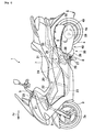
- Fig. 1 is a side view of a motorcycle 1 provided with a clutch 50 as an example of the embodiment.
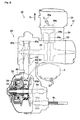
- Fig. 2 is a partial sectional view of an engine unit 30 along line II-II shown in Fig. 1 .
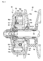
- Fig. 3 is an enlarged view of Fig. 2 .
- an engine unit has a centrifugal clutch.
- a vehicle such as a straddle-type vehicle, has the engine unit.
- the straddle-type vehicle is, for example, a motorcycle (including a motor scooter), a snowmobile, and a four-wheeled buggy or the like.
- a straddle-type vehicle has a body-frame and a seat on which a rider can be seated straddling the body frame when being seated.
- the motorcycle 1 is provided with a front wheel 3, a rear wheel 4 and a vehicle body frame 20 in addition to the engine unit 30.
- the engine unit 30 is provided with an engine 31 generating torque, and a transmission unit 40 transmitting the torque to the rear wheel 4 and rotating the rear wheel 4.
- the transmission unit 40 includes a transmission 41 and the centrifugal clutch 50, which are housed in a case 49.
- the front wheel 3 which is arranged at the front of a vehicle body, is provided so as to rotate to the left and right centering on a steering shaft 29 according to the operation of a handlebar 5.
- the steering shaft 29 which is inserted into a head pipe 21 provided at the front end of the vehicle body frame 20, is rotatably supported by the head pipe 21.
- the steering shaft 29 has an upper end to which the handlebar 5 is coupled and a lower end to which a front suspension 6 is coupled.
- the front wheel 3 has an axle 3a supported by the lower end of the front suspension 6, and thereby the front wheel 3 rotates to the left and right with the handlebar 5 and the front suspension 6.
- the rear wheel 4 is arranged below a seat 7 on the rear of the vehicle body.
- the motorcycle 1 is a unit swing type vehicle.
- the rear wheel 4 is provided so as to enable the rear wheel 4 to move vertically to the vehicle body frame 20 with the engine unit 30.
- the rear wheel 4 has an axle 4a of which one side is arranged in the case 49, the axle 4a rotatably supported by the case 49 (see Fig. 2 ).
- the engine unit 30 can be vertically moved centering on a pivot shaft 8 supported by the vehicle body frame 20, and thereby the rear wheel 4 and the engine unit 30 can be integrally and vertically moved to the vehicle body frame 20.
- the vehicle body frame 20 is provided with a vertical tube 25 vertically extending below the seat 7, and a stay 26 extending slantingly upward and toward the rear of the vehicle body from a position on the way of the vertical tube 25. Therebetween, a vertically long gusset 28 is provided.
- the vehicle body frame 20 has a pivot supporting part 27 into which the pivot shaft 8 is inserted and which supports the pivot shaft 8. The pivot supporting part 27 is held by the lower part of the gusset 28.
- the engine unit 30 has a supported part 39, which is attached to the pivot shaft 8.
- the engine 31 of the engine unit 30 has a crankcase 33 housing a crankshaft 32 (see Fig. 2 ).
- the supported part 39 is provided so as to project forward from the underside of the crankcase 33.
- the supported part 39 has a cylindrically formed tip, into which the pivot shaft 8 is inserted. Thereby, the engine unit 30 can be vertically moved centering on the pivot shaft 8.
- the vehicle body frame 20 is provided with an upper tube 22 and an under tube 23 in addition to the head pipe 21 or the like.
- the front end of the upper tube 22 and the upper end (front end) of the under tube 23 are connected to the head pipe 21.
- the under tube 23, which is located below the upper tube 22, extends downward from the head pipe 21 and then bends backward. Then, the under tube 23 further extends rearward and has a rear end connected to the vertical tube 25.
- the engine unit 30 is provided with the engine 31.
- the engine 31 has a cylinder block 34 in which a cylinder 34a is formed, and a cylinder head 35 in which a spark plug 35a is provided, in addition to the crankcase 33 described above.
- a piston 34b is arranged in the cylinder 34a, and the piston 34b is coupled to the crankshaft 32 via a connecting rod 34c.
- the reciprocating movement of the piston 34b is converted into a rotating movement by the crankshaft 32, and the rotating movement is output to the downstream side (herein, the transmission 41 or the like) of a torque transmission path.
- the rotating speed of the crankshaft 32 fluctuates according to the engine stroke (intake stroke and combustion stroke or the like) and the operational state of the engine 31.
- the transmission 41 is provided on one side (in the example of Fig. 2 , on the left relative to a traveling direction (a direction shown by Fr)) of the crankshaft 32.
- the transmission 41 which is a continuously variable transmission, is provided with a driving pulley 42, a driven pulley 43, and a belt 44 applied over the driving pulley 42 and the driven pulley 43 and transmitting the rotation of the driving pulley 42 to the driven pulley 43.
- the driving pulley 42 which is provided on the crankshaft 32, interlocks with the crankshaft 32.
- a driven shaft (central shaft) 59 is arranged to the rear of the crankshaft 32.
- the driven pulley 43 which is arranged on the driven shaft 59, is provided so as to be able to idle to the driven shaft 59.
- bearings 61, 62 are fitted to the driven shaft 59, and a cylindrical collar 46 is fitted to the exteriors of the bearings 61, 62 (see Fig. 3 ).
- the driven pulley 43 is fitted to the exterior of the collar 46.
- the driving pulley 42 includes a movable sheave 42a of which the movement in the axial direction of the crankshaft 32 is allowed and a fixed sheave 42b of which the movement in the axial direction is regulated, and the front side of the belt 44 is arranged therebetween.
- the driven pulley 43 includes a movable sheave 43a of which the movement in the axial direction of the driven shaft 59 is allowed and a fixed sheave 43b of which the movement in the axial direction is regulated, and the rear side of the belt 44 is arranged therebetween.
- the centrifugal clutch 50 includes a clutch outer 58 and a clutch inner 51 provided so as to be relatively rotatable to the clutch outer 58.
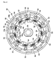
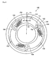
- Fig. 4 is a front view of the centrifugal clutch 50.
- the clutch outer 58 is provided on the outer side of the clutch inner 51 so as to surround the clutch inner 51.
- the clutch outer 58 has a disk-shaped plate part 58a and a cylindrical tube part 58b rising in the axial direction from the circumferential edge of the plate part 58a.
- the tube part 58b surrounds the clutch inner 51.
- the clutch inner 51 is provided so as to be rotatable around the driven shaft 59.
- the clutch inner 51 includes a disk-shaped plate 52 having a hole 52a formed in the center of the plate 52, and the collar 46 is fitted to the hole 52a.
- the hole 52a and the outer shape of the collar 46 on a position corresponding to the hole 52a are formed so that the collar 46 and the plate 52 integrally rotate (see Fig. 4 ).
- the collar 46 and the driven shaft 59 can idle.
- the clutch inner 51 is provided so as to be able to idle to the driven shaft 59 around the driven shaft 59.
- the clutch outer 58 and the driven shaft 59 are provided so as to integrally rotate. Specifically, as shown in Fig. 3 , a hole 58c is formed in the center of the plate part 58a of the clutch outer 58. A cylindrical collar 57 integrally rotating with the plate part 58a is fitted to the hole 58c, and the driven shaft 59 is fitted to the interior of the collar 57. A spline is formed in the internal circumferential surface of the collar 57. The spline is engaged with a spline formed in the external circumferential surface of the driven shaft 59. Thereby, the clutch outer 58 and the driven shaft 59 integrally rotate.
- the clutch inner 51 is provided with a plurality of (herein, eleven) clutch weights 53 and weight supporting shafts 54 in addition to the plate 52.
- the plurality of weight supporting shafts 54 are arranged so as to surround the driven shaft 59 on positions separated from the driven shaft 59 in the radial direction thereof.
- Each of the weight supporting shafts 54 has a first end 54a supported by the plate 52.
- holes 52b are formed on the external circumferential side of the plate 52, and the first end 54a is fitted to the hole 52b.
- the plurality of clutch weights 53 are also arranged so as to surround the driven shaft 59.
- Each of the clutch weights 53 which is supported by the weight supporting shaft 54, provided so as to be movable to the clutch outer 58 side centering on the weight supporting shaft 54. That is, a hole penetrating the clutch weight 53 in the axial direction is formed in the clutch weight 53, and the weight supporting shaft 54 is inserted into the hole.
- a plate-like friction material 53b is provided on the external circumferential surface of the clutch weight 53.
- the friction material 53b is pressed against the internal circumferential surface of the tube part 58b.
- the torque of the clutch inner 51 is transmitted to the clutch outer 58 by frictional force generated therebetween.
- the axle 4a of the rear wheel 4 is located to the rear of the driven shaft 59.
- the driven shaft 59 is rotated by the torque (hereinafter, referred to as clutch-transmission torque) transmitted to the clutch outer 58 from the clutch inner 51.
- the rotation is transmitted to the axle 4a of the rear wheel 4 via an intermediate shaft which is not shown.
- the clutch weight 53 is pulled by a spring 55 in the direction where the friction material 53b separates from the clutch outer 58.
- a spring attaching part 53c and a spring attaching part 53d are formed in the clutch weight 53.
- the spring 55 has a first end attached to the spring attaching part 53c and a second end attached to the spring attaching part 53d of the adjacent clutch weight 53.
- the spring attaching part 53c is located on the opposite side from the friction material 53b with the weight supporting shaft 54 interposed therebetween.
- the spring 55 pulls the spring attaching part 53c in the direction where the friction material 53b separates from the internal circumferential surface of the clutch outer 58.
- the spring 55 is provided so that the force of the spring 55 pulling the spring attaching part 53d is generally coincident with the radial direction of the weight supporting shaft 54. The generation of moment around the weight supporting shaft 54 is suppressed by the force of the spring 55 pulling the spring attaching part 53d.
- a circular holding ring 64 which is fitted to second ends 54b of the plurality of weight supporting shafts 54, holds the second ends 54b (see Figs. 3 or 4 ).
- This holding ring 64 regulates the movement of the weight supporting shaft 54 in the radial direction.
- a stop ring 65 for preventing loss of the holding ring 64 is fitted to the second end 54b (see Fig. 3 ).
- Fig. 4 only a part of the holding ring 64 is shown by a solid line, and the other part is shown by a two-dot chain line.
- Fig. 5 is a front view of the clutch weight 53.
- the clutch weight 53 has at its part a centroid displacement part 53e formed of a material different from the other part of the clutch weight 53.
- This centroid displacement part 53e draws a centroid position Cg of the clutch weight 53 to the driven shaft 59 side. That is, the centroid position Cg of the clutch weight 53 having the centroid displacement part 53e is closer to the driven shaft 59 as compared with the centroid position of the clutch weight having no centroid displacement part 53e.
- the centroid displacement part 53e is formed of a material having a specific gravity larger than that of the other part of the clutch weight 53. That is, the clutch weight 53 has a weight main body 53f formed of a material (for example, aluminum and zinc alloy). The centroid displacement part 53e is formed of a material having a specific gravity larger than that of the weight main body 53f.
- the centroid displacement part 53e is located on further the driven shaft 59 side than the weight supporting shaft 54. That is, the distance between the driven shaft 59 and the centroid displacement part 53e is shorter than the distance between the driven shaft 59 and the weight supporting shaft 54.
- a hole is formed on the position on the driven shaft 59 side than the weight supporting shaft 54 in the weight main body 53f, and the centroid displacement part 53e is fitted to this hole (see Fig. 3 ).
- the weight main body 53f has an extension part 53k extending to the driven shaft 59 side from the position where the weight supporting shaft 54 is provided.
- the length DL of the weight main body 53f in the radial direction of the driven shaft 59 is longer than the width Dw of the weight main body 53f in the circumferential direction of the driven shaft 59.
- the hole to which the centroid displacement part 53e is fitted is formed in the extension part 53k.
- the centroid displacement part 53e is fixed to the weight main body 53f.
- the centroid displacement part 53e is fixed to the weight main body 53f by a bolt 56 fitted from the rear side of the hole to which the centroid displacement part 53e is fitted.
- a recessed part 53h is formed in the weight main body 53f, the recessed part 53h reducing the weight of the external circumferential side of the weight main body 53f and drawing the centroid position Cg of the clutch weight 53 to the driven shaft 59 side (see Fig. 3 ).
- the recessed part 53h is located on the outer side in the radial direction of the centroid displacement part 53e.
- a hole reducing the weight of the external circumferential side of the weight main body 53f may be formed in the weight main body 53f.
- the centroid position Cg of the clutch weight 53 is located on further the driven shaft 59 side than an intersection point Pf of a straight line L1 and a perpendicular line L2.
- the straight line L1 of the radial direction of the driven shaft 59 passes through the centroid position Cg
- the perpendicular line L2 is perpendicular to the straight line L1 and passes through the center of the weight supporting shaft 54. That is, the weight supporting shaft 54 is located on further the external circumferential side than another straight line L3 passing through the centroid position Cg and being perpendicular to the straight line L1.
- the sizes and positions of the recessed part 53h and centroid displacement part 53e are selected so that the centroid position Cg is located on further the driven shaft 59 side than the intersection point Pf of the perpendicular line L2 and straight line L1.
- the centrifugal clutch 50 described above is provided with the clutch inner 51 provided so as to be rotatable around the driven shaft 59 and the clutch outer 58 provided so as to be relatively rotatable to the clutch inner 51 on the outer side of the clutch inner 51.
- the clutch inner 51 is provided with the weight supporting shafts 54 and the clutch weights 53 supported by the weight supporting shafts 54 so that the clutch weights 53 can be moved to the clutch outer 58 side centering on the weight supporting shafts 54.
- the centroid position Cg of the clutch weight 53 is located on further the driven shaft 59 side than an intersection point Pf of a straight line L1 and a perpendicular line L2.
- the straight line L1 of the radial direction of the driven shaft 59 passes through the centroid position Cg, and the perpendicular line L2 is perpendicular to the straight line L1 and passes through the center of the weight supporting shaft 54.
- Fig. 6 is a diagram for explaining force applied to the clutch weight 53.
- Fig. 6 shows the force applied to the clutch weight 53 as example when the rotating speed of the clutch inner 51 rises.
- centrifugal force Fc applied to the clutch weight 53 increases.
- inertial force Fi3 is generated in the direction perpendicular to the straight line L1, and thereby torque Ti3 centering on the weight supporting shaft 54 is generated.
- This torque Ti3 can act as force separating the clutch weight 53 from the clutch outer 51 to suppress the increase of the clutch connection force. That is, torque centering on the weight supporting shaft 54 is also generated by the centrifugal force Fc. When the centrifugal force Fc increases, the torque also increases. Since the centroid position Cg is located on further the driven shaft 59 side than the intersection point Pf, the direction of the increase amount ⁇ Tfc of the torque caused by the centrifugal force Fc is opposite to that of the torque Ti3, and these torques are mutually canceled each other to suppress the increase of the clutch connection force.
- the torque caused by the inertial force can act as force for pressing the clutch weight 53 against the clutch outer 58 to suppress the reduction of the clutch connection force. That is, the reduction amount of the torque centering on the weight supporting shaft 54 caused by the reduction of the centrifugal force Fc and the torque centering on the weight supporting shaft 54 caused by the inertial force are mutually canceled each other to suppress the reduction of the clutch connection force.
- the fluctuation in the clutch connection force caused by the fluctuation in the rotating speed of the clutch inner 51 is suppressed, the fluctuation in the clutch-transmission torque is suppressed.
- the clutch weights 53 has at its part the centroid displacement part 53e formed of the material different from the other part of the clutch weight 53 and drawing the centroid position Cg of the clutch weight 53 to the driven shaft 59 side.
- the fluctuation in the clutch-transmission torque caused by the fluctuation in the rotating speed of the clutch inner 51 can be suppressed. That is, although the inertial force Fi3 is generated in the clutch weight 53 when the rotating speed of the clutch inner 51 rises, the centroid position Cg of the clutch weight 53 is drawn to the driven shaft 59 side by the centroid displacement part 53e. Thereby, the torque Ti3 generated by the inertial force Fi3 is reduced as compared with the clutch having no centroid displacement part 53e. Therefore, the fluctuation in the clutch connection force caused by the fluctuation in the rotating speed of the clutch inner 51 is suppressed, and as a result, the fluctuation in the clutch-transmission torque is suppressed.
- the centroid position Cg of the clutch weight 53 is located on further the driven shaft 59 side than the intersection point Pf. Therefore, the torque Ti3 acts in the opposite direction to that of the torque ( ⁇ Tfc described above) generated by the increase and decrease of the centrifugal force Fc.
- the torque Ti3 is a negative value.
- the centroid displacement part 53e is fitted to the hole formed in the weight main body 53f.
- the centroid displacement part may be fixed to an internal circumferential surface 53j of the weight main body 53f (see Fig. 5 ).
- the centroid displacement part 53e which is formed of the material having the specific gravity larger than that of the weight main body 53f, is provided on the internal circumferential side of the clutch weights 53.
- the centroid displacement part 53e may be formed of the material having the specific gravity lower than that of the weight main body 53f, and may be provided on the external circumferential side of the clutch weight 53 so that the centroid position Cg of the clutch weight 53 is drawn to the driven shaft 59 side.
- the centroid displacement part 53e is formed of the material different from that of the weight main body 53f, and furthermore, the centroid position Cg is located on further the driven shaft 59 side than the intersection point Pf of the perpendicular line L2 and straight line L1.
- the centroid position Cg may be located on further the driven shaft 59 side than the intersection point Pf by the centroid displacement part formed of the same material as that of the weight main body 53f.
- the centroid displacement part may project in the axial direction of the driven shaft 59 from the weight main body 53f, or may be formed so as to project to the driven shaft 59 side.
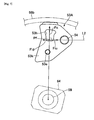
- Fig. 7 is a diagram for explaining force applied to a clutch weight 53A according to this embodiment.
- the same parts as those described above are designated by the same reference numerals.
- the centroid of the clutch weight 53A is located at the intersection point Pf.
- the weight supporting shaft 54 is located on the action line of inertial force Fu or Fd caused by the fluctuation in the rotating speed of the clutch inner 51. Therefore, even when the rotating speed of the clutch inner 51 rises, the torque centering on the weight supporting shaft 54 is not generated by the inertial force Fu or Fd. Therefore, the fluctuation in the clutch-transmission torque caused by the fluctuation in the rotating speed of the clutch inner 51 can be suppressed.
- the centroid displacement part 53e is formed of the material different from that of the weight main body 53f, and furthermore, the centroid position Cg is located on further the driven shaft 59 side than the intersection point Pf.
- the centroid displacement part 53e is formed of the material different from that of the weight main body 53f; the centroid position Cg of the clutch weight 53 is drawn to the driven shaft 59 side; but the centroid position Cg may be still located on the external circumferential side than the intersection point Pf.
- a centrifugal clutch comprising: a clutch inner provided so as to be rotatable around a central shaft; and a clutch outer provided so as to be relatively rotatable to the clutch inner on the outer side of the clutch inner, wherein the clutch inner comprises: a weight supporting shaft; and a clutch weight supported by the weight supporting shaft so as to be movable to the clutch outer side centering on the weight supporting shaft, and a centroid position of the clutch weight is located at an intersection point of a straight line of a radial direction of the central shaft passing through the centroid position and a perpendicular line being perpendicular to the straight line and passing through the weight supporting shaft, or on further the central shaft side than the intersection point.
- the clutch weight has a centroid displacement part drawing the centroid position to the central shaft side.
- centroid displacement part is formed of a material different from that of other part of the clutch weight.
- centroid displacement part is formed of a material having a specific gravity larger than that of other part of the clutch weight.
- a centrifugal clutch comprising: a clutch inner provided so as to be rotatable around a central shaft; and a clutch outer provided so as to be relatively rotatable to the clutch inner on the outer side of the clutch inner, wherein the clutch inner comprises: a weight supporting shaft; and a clutch weight supported by the weight supporting shaft so as to be movable to the clutch outer side centering on the weight supporting shaft, and the clutch weight has at its part a centroid displacement part formed of a material different from that of other part of the clutch weight and drawing the centroid position of the clutch weight to the central shaft side.
- the centrifugal clutch of said other embodiment can also suppress the fluctuation in the clutch-transmission torque caused by the fluctuation in the rotating speed of the clutch inner. That is, when the rotating speed of the clutch inner rises or declines, as described above, the inertial force is generated in the clutch weight. However, since the centroid position of the clutch weight is drawn to the central shaft side by the centroid displacement part in this centrifugal clutch, the torque (in the example of Fig. 8 , the torque Ti1 and torque Ti2) generated by the inertial force can be reduced as compared with the centrifugal clutch having no centroid displacement part. Thereby, when the rotating speed of the clutch inner rises, the increase of the clutch connection force caused by the rise can be suppressed. When the rotating speed of the clutch inner declines, the reduction of the clutch connection force caused by the declination can be suppressed. As a result, the fluctuation in the clutch-transmission torque can be suppressed.
- said other embodiment can be combined with the previous embodiment.
- the centroid displacement part of the clutch weight is formed of a material having a specific gravity larger than that of other part of the clutch weight.
- an engine unit comprises the centrifugal clutch according to one of the preceding embodiments.
- a straddle-type vehicle comprises the engine unit according to the preceding embodiment.
- an embodiment of a centrifugal clutch is provided with a clutch inner 51 provided so as to be rotatable around a driven shaft 59 and a clutch outer 58 provided so as to be relatively rotatable to the clutch inner.
- the clutch inner 51 is provided with a weight supporting shaft 54 located on a position separating from the driven shaft, and a clutch weight 53 supported by the weight supporting shaft 54 so that the clutch weight 53 can move to a clutch outer 58 side centering on the weight supporting shaft 54.
- the centroid position Cg of the clutch weight 53 is located on further the driven shaft 59 side than an intersection point Pf of a straight line L1 and a perpendicular line L2.
- the straight line L1 of the radial direction of the driven shaft 59 passes through the centroid position Cg, and the perpendicular line L2 is perpendicular to the straight line L1 and passes through the center of the weight supporting shaft 54.
Landscapes
- Engineering & Computer Science (AREA)
- General Engineering & Computer Science (AREA)
- Mechanical Engineering (AREA)
- One-Way And Automatic Clutches, And Combinations Of Different Clutches (AREA)
Applications Claiming Priority (1)
| Application Number | Priority Date | Filing Date | Title |
|---|---|---|---|
| JP2007341395A JP5203695B2 (ja) | 2007-12-28 | 2007-12-28 | 遠心クラッチ、エンジンユニット及び鞍乗型車両 |
Publications (3)
| Publication Number | Publication Date |
|---|---|
| EP2075481A2 true EP2075481A2 (de) | 2009-07-01 |
| EP2075481A3 EP2075481A3 (de) | 2013-04-24 |
| EP2075481B1 EP2075481B1 (de) | 2014-04-09 |
Family
ID=40512292
Family Applications (1)
| Application Number | Title | Priority Date | Filing Date |
|---|---|---|---|
| EP08022383.7A Active EP2075481B1 (de) | 2007-12-28 | 2008-12-23 | Zentrifugalkupplung |
Country Status (3)
| Country | Link |
|---|---|
| EP (1) | EP2075481B1 (de) |
| JP (1) | JP5203695B2 (de) |
| ES (1) | ES2458622T3 (de) |
Cited By (4)
| Publication number | Priority date | Publication date | Assignee | Title |
|---|---|---|---|---|
| WO2012005594A2 (en) | 2010-07-09 | 2012-01-12 | Innocore Technologies B.V. | Biodegradable phase separated segmented multi block co-polymers and release of biologically active polypeptides |
| CN102725555A (zh) * | 2010-01-27 | 2012-10-10 | 株式会社F.C.C. | 离心式离合器设备 |
| US20170058904A1 (en) * | 2015-09-02 | 2017-03-02 | Johnson Electric S.A. | Fluid driving device, motor assembly and centrifugal friction clutch thereof |
| WO2025099133A1 (en) * | 2023-11-07 | 2025-05-15 | Papizturbine Europe Gmbh | Centrifugal clutch for a gearbox |
Citations (1)
| Publication number | Priority date | Publication date | Assignee | Title |
|---|---|---|---|---|
| JP2007120601A (ja) | 2005-10-27 | 2007-05-17 | Honda Motor Co Ltd | 遠心クラッチ |
Family Cites Families (7)
| Publication number | Priority date | Publication date | Assignee | Title |
|---|---|---|---|---|
| BE332926A (de) * | ||||
| JPS4633443Y1 (de) * | 1969-06-02 | 1971-11-18 | ||
| JPH073251B2 (ja) * | 1986-07-15 | 1995-01-18 | ヤマハ発動機株式会社 | 遠心クラツチ装置 |
| JPH01182651A (ja) * | 1988-01-08 | 1989-07-20 | Nissan Motor Co Ltd | 可変慣性能率フライホイール |
| JP3447401B2 (ja) * | 1994-11-28 | 2003-09-16 | 本田技研工業株式会社 | ベルト式無段変速装置 |
| IT1274134B (it) * | 1994-12-16 | 1997-07-15 | Cdc Snc | Frizione centrifuga con regolazione variabile di innesto |
| JP2004036806A (ja) * | 2002-07-05 | 2004-02-05 | Honda Motor Co Ltd | 遠心クラッチ |
-
2007
- 2007-12-28 JP JP2007341395A patent/JP5203695B2/ja active Active
-
2008
- 2008-12-23 EP EP08022383.7A patent/EP2075481B1/de active Active
- 2008-12-23 ES ES08022383.7T patent/ES2458622T3/es active Active
Patent Citations (1)
| Publication number | Priority date | Publication date | Assignee | Title |
|---|---|---|---|---|
| JP2007120601A (ja) | 2005-10-27 | 2007-05-17 | Honda Motor Co Ltd | 遠心クラッチ |
Cited By (5)
| Publication number | Priority date | Publication date | Assignee | Title |
|---|---|---|---|---|
| CN102725555A (zh) * | 2010-01-27 | 2012-10-10 | 株式会社F.C.C. | 离心式离合器设备 |
| CN102725555B (zh) * | 2010-01-27 | 2015-02-11 | 株式会社F.C.C. | 离心式离合器设备 |
| WO2012005594A2 (en) | 2010-07-09 | 2012-01-12 | Innocore Technologies B.V. | Biodegradable phase separated segmented multi block co-polymers and release of biologically active polypeptides |
| US20170058904A1 (en) * | 2015-09-02 | 2017-03-02 | Johnson Electric S.A. | Fluid driving device, motor assembly and centrifugal friction clutch thereof |
| WO2025099133A1 (en) * | 2023-11-07 | 2025-05-15 | Papizturbine Europe Gmbh | Centrifugal clutch for a gearbox |
Also Published As
| Publication number | Publication date |
|---|---|
| JP2009162285A (ja) | 2009-07-23 |
| JP5203695B2 (ja) | 2013-06-05 |
| EP2075481B1 (de) | 2014-04-09 |
| EP2075481A3 (de) | 2013-04-24 |
| ES2458622T3 (es) | 2014-05-06 |
Similar Documents
| Publication | Publication Date | Title |
|---|---|---|
| CN1171746C (zh) | 山地行驶用四轮车 | |
| JP2008196562A (ja) | 動力ユニット、及び鞍乗型車両 | |
| JP3156420U (ja) | クラッチ、無段変速機、それらを備えるエンジンユニット、及び鞍乗型車両 | |
| CN101315110A (zh) | 离心式离合器和包括该离心式离合器的跨骑式车辆 | |
| EP2075481A2 (de) | Zentrifugalkupplung | |
| CN1765687A (zh) | 摩托车 | |
| EP1741964B1 (de) | Fahrzeugantrieb und Fahrzeug umfassend einen solchen Fahrzeugantrieb | |
| US8215439B2 (en) | Dry clutch, and motorcycle equipped with the same | |
| EP3072798B1 (de) | Fahrzeug mit antriebswelle | |
| EP1864901B1 (de) | Motorrad | |
| EP1950132B1 (de) | Fahrzeug | |
| EP2546550B1 (de) | Getriebevorrichtung und Sattelfahrzeug damit | |
| EP3521659B1 (de) | Angetriebene riemenscheibenvorrichtung für automatikgetriebe vom keilriementyp | |
| JP5036329B2 (ja) | 鞍乗型車両 | |
| JP7598990B1 (ja) | 遠心クラッチ、および車両 | |
| JP6071579B2 (ja) | 回転軸の軸受構造 | |
| CN100443356C (zh) | 摩托车 | |
| JP3155809U (ja) | エンジンおよび鞍乗型車両 | |
| JP6598176B1 (ja) | クランク軸へのギヤ板の取付構造 | |
| JP2024004961A (ja) | 内燃機関および鞍乗型車両 | |
| JP2025152021A (ja) | 電動無段変速装置 | |
| WO2026028408A1 (ja) | 無段変速機用シーブ、無段変速機、鞍乗型車両および無段変速機用シーブの製造方法 | |
| JP2025151460A (ja) | 電動無段変速装置 | |
| JP5419840B2 (ja) | 鞍乗型車両のパワーユニット | |
| JP2009092182A (ja) | エンジンおよび鞍乗型車両 |
Legal Events
| Date | Code | Title | Description |
|---|---|---|---|
| PUAI | Public reference made under article 153(3) epc to a published international application that has entered the european phase |
Free format text: ORIGINAL CODE: 0009012 |
|
| AK | Designated contracting states |
Kind code of ref document: A2 Designated state(s): AT BE BG CH CY CZ DE DK EE ES FI FR GB GR HR HU IE IS IT LI LT LU LV MC MT NL NO PL PT RO SE SI SK TR |
|
| AX | Request for extension of the european patent |
Extension state: AL BA MK RS |
|
| PUAL | Search report despatched |
Free format text: ORIGINAL CODE: 0009013 |
|
| AK | Designated contracting states |
Kind code of ref document: A3 Designated state(s): AT BE BG CH CY CZ DE DK EE ES FI FR GB GR HR HU IE IS IT LI LT LU LV MC MT NL NO PL PT RO SE SI SK TR |
|
| AX | Request for extension of the european patent |
Extension state: AL BA MK RS |
|
| RIC1 | Information provided on ipc code assigned before grant |
Ipc: F16D 43/14 20060101AFI20130315BHEP Ipc: F16D 43/18 20060101ALI20130315BHEP |
|
| 17P | Request for examination filed |
Effective date: 20130814 |
|
| RBV | Designated contracting states (corrected) |
Designated state(s): AT BE BG CH CY CZ DE DK EE ES FI FR GB GR HR HU IE IS IT LI LT LU LV MC MT NL NO PL PT RO SE SI SK TR |
|
| GRAP | Despatch of communication of intention to grant a patent |
Free format text: ORIGINAL CODE: EPIDOSNIGR1 |
|
| AKX | Designation fees paid |
Designated state(s): AT BE BG CH CY CZ DE DK EE ES FI FR GB GR HR HU IE IS IT LI LT LU LV MC MT NL NO PL PT RO SE SI SK TR |
|
| INTG | Intention to grant announced |
Effective date: 20131206 |
|
| GRAS | Grant fee paid |
Free format text: ORIGINAL CODE: EPIDOSNIGR3 |
|
| GRAA | (expected) grant |
Free format text: ORIGINAL CODE: 0009210 |
|
| AK | Designated contracting states |
Kind code of ref document: B1 Designated state(s): AT BE BG CH CY CZ DE DK EE ES FI FR GB GR HR HU IE IS IT LI LT LU LV MC MT NL NO PL PT RO SE SI SK TR |
|
| REG | Reference to a national code |
Ref country code: GB Ref legal event code: FG4D |
|
| REG | Reference to a national code |
Ref country code: AT Ref legal event code: REF Ref document number: 661514 Country of ref document: AT Kind code of ref document: T Effective date: 20140415 Ref country code: CH Ref legal event code: EP |
|
| REG | Reference to a national code |
Ref country code: ES Ref legal event code: FG2A Ref document number: 2458622 Country of ref document: ES Kind code of ref document: T3 Effective date: 20140506 |
|
| REG | Reference to a national code |
Ref country code: IE Ref legal event code: FG4D |
|
| REG | Reference to a national code |
Ref country code: DE Ref legal event code: R096 Ref document number: 602008031348 Country of ref document: DE Effective date: 20140522 |
|
| REG | Reference to a national code |
Ref country code: AT Ref legal event code: MK05 Ref document number: 661514 Country of ref document: AT Kind code of ref document: T Effective date: 20140409 |
|
| REG | Reference to a national code |
Ref country code: NL Ref legal event code: VDEP Effective date: 20140409 |
|
| REG | Reference to a national code |
Ref country code: LT Ref legal event code: MG4D |
|
| PG25 | Lapsed in a contracting state [announced via postgrant information from national office to epo] |
Ref country code: NL Free format text: LAPSE BECAUSE OF FAILURE TO SUBMIT A TRANSLATION OF THE DESCRIPTION OR TO PAY THE FEE WITHIN THE PRESCRIBED TIME-LIMIT Effective date: 20140409 Ref country code: FI Free format text: LAPSE BECAUSE OF FAILURE TO SUBMIT A TRANSLATION OF THE DESCRIPTION OR TO PAY THE FEE WITHIN THE PRESCRIBED TIME-LIMIT Effective date: 20140409 Ref country code: NO Free format text: LAPSE BECAUSE OF FAILURE TO SUBMIT A TRANSLATION OF THE DESCRIPTION OR TO PAY THE FEE WITHIN THE PRESCRIBED TIME-LIMIT Effective date: 20140709 Ref country code: IS Free format text: LAPSE BECAUSE OF FAILURE TO SUBMIT A TRANSLATION OF THE DESCRIPTION OR TO PAY THE FEE WITHIN THE PRESCRIBED TIME-LIMIT Effective date: 20140809 Ref country code: LT Free format text: LAPSE BECAUSE OF FAILURE TO SUBMIT A TRANSLATION OF THE DESCRIPTION OR TO PAY THE FEE WITHIN THE PRESCRIBED TIME-LIMIT Effective date: 20140409 Ref country code: BG Free format text: LAPSE BECAUSE OF FAILURE TO SUBMIT A TRANSLATION OF THE DESCRIPTION OR TO PAY THE FEE WITHIN THE PRESCRIBED TIME-LIMIT Effective date: 20140709 Ref country code: GR Free format text: LAPSE BECAUSE OF FAILURE TO SUBMIT A TRANSLATION OF THE DESCRIPTION OR TO PAY THE FEE WITHIN THE PRESCRIBED TIME-LIMIT Effective date: 20140710 |
|
| PG25 | Lapsed in a contracting state [announced via postgrant information from national office to epo] |
Ref country code: HR Free format text: LAPSE BECAUSE OF FAILURE TO SUBMIT A TRANSLATION OF THE DESCRIPTION OR TO PAY THE FEE WITHIN THE PRESCRIBED TIME-LIMIT Effective date: 20140409 Ref country code: SE Free format text: LAPSE BECAUSE OF FAILURE TO SUBMIT A TRANSLATION OF THE DESCRIPTION OR TO PAY THE FEE WITHIN THE PRESCRIBED TIME-LIMIT Effective date: 20140409 Ref country code: LV Free format text: LAPSE BECAUSE OF FAILURE TO SUBMIT A TRANSLATION OF THE DESCRIPTION OR TO PAY THE FEE WITHIN THE PRESCRIBED TIME-LIMIT Effective date: 20140409 Ref country code: PL Free format text: LAPSE BECAUSE OF FAILURE TO SUBMIT A TRANSLATION OF THE DESCRIPTION OR TO PAY THE FEE WITHIN THE PRESCRIBED TIME-LIMIT Effective date: 20140409 Ref country code: AT Free format text: LAPSE BECAUSE OF FAILURE TO SUBMIT A TRANSLATION OF THE DESCRIPTION OR TO PAY THE FEE WITHIN THE PRESCRIBED TIME-LIMIT Effective date: 20140409 |
|
| PG25 | Lapsed in a contracting state [announced via postgrant information from national office to epo] |
Ref country code: PT Free format text: LAPSE BECAUSE OF FAILURE TO SUBMIT A TRANSLATION OF THE DESCRIPTION OR TO PAY THE FEE WITHIN THE PRESCRIBED TIME-LIMIT Effective date: 20140811 |
|
| REG | Reference to a national code |
Ref country code: DE Ref legal event code: R097 Ref document number: 602008031348 Country of ref document: DE |
|
| PG25 | Lapsed in a contracting state [announced via postgrant information from national office to epo] |
Ref country code: SK Free format text: LAPSE BECAUSE OF FAILURE TO SUBMIT A TRANSLATION OF THE DESCRIPTION OR TO PAY THE FEE WITHIN THE PRESCRIBED TIME-LIMIT Effective date: 20140409 Ref country code: BE Free format text: LAPSE BECAUSE OF FAILURE TO SUBMIT A TRANSLATION OF THE DESCRIPTION OR TO PAY THE FEE WITHIN THE PRESCRIBED TIME-LIMIT Effective date: 20140409 Ref country code: DK Free format text: LAPSE BECAUSE OF FAILURE TO SUBMIT A TRANSLATION OF THE DESCRIPTION OR TO PAY THE FEE WITHIN THE PRESCRIBED TIME-LIMIT Effective date: 20140409 Ref country code: CZ Free format text: LAPSE BECAUSE OF FAILURE TO SUBMIT A TRANSLATION OF THE DESCRIPTION OR TO PAY THE FEE WITHIN THE PRESCRIBED TIME-LIMIT Effective date: 20140409 Ref country code: EE Free format text: LAPSE BECAUSE OF FAILURE TO SUBMIT A TRANSLATION OF THE DESCRIPTION OR TO PAY THE FEE WITHIN THE PRESCRIBED TIME-LIMIT Effective date: 20140409 Ref country code: RO Free format text: LAPSE BECAUSE OF FAILURE TO SUBMIT A TRANSLATION OF THE DESCRIPTION OR TO PAY THE FEE WITHIN THE PRESCRIBED TIME-LIMIT Effective date: 20140409 |
|
| PLBE | No opposition filed within time limit |
Free format text: ORIGINAL CODE: 0009261 |
|
| STAA | Information on the status of an ep patent application or granted ep patent |
Free format text: STATUS: NO OPPOSITION FILED WITHIN TIME LIMIT |
|
| 26N | No opposition filed |
Effective date: 20150112 |
|
| REG | Reference to a national code |
Ref country code: DE Ref legal event code: R097 Ref document number: 602008031348 Country of ref document: DE Effective date: 20150112 |
|
| PG25 | Lapsed in a contracting state [announced via postgrant information from national office to epo] |
Ref country code: SI Free format text: LAPSE BECAUSE OF FAILURE TO SUBMIT A TRANSLATION OF THE DESCRIPTION OR TO PAY THE FEE WITHIN THE PRESCRIBED TIME-LIMIT Effective date: 20140409 Ref country code: LU Free format text: LAPSE BECAUSE OF FAILURE TO SUBMIT A TRANSLATION OF THE DESCRIPTION OR TO PAY THE FEE WITHIN THE PRESCRIBED TIME-LIMIT Effective date: 20141223 |
|
| REG | Reference to a national code |
Ref country code: CH Ref legal event code: PL |
|
| REG | Reference to a national code |
Ref country code: IE Ref legal event code: MM4A |
|
| PG25 | Lapsed in a contracting state [announced via postgrant information from national office to epo] |
Ref country code: LI Free format text: LAPSE BECAUSE OF NON-PAYMENT OF DUE FEES Effective date: 20141231 Ref country code: CH Free format text: LAPSE BECAUSE OF NON-PAYMENT OF DUE FEES Effective date: 20141231 Ref country code: IE Free format text: LAPSE BECAUSE OF NON-PAYMENT OF DUE FEES Effective date: 20141223 |
|
| REG | Reference to a national code |
Ref country code: FR Ref legal event code: PLFP Year of fee payment: 8 |
|
| PG25 | Lapsed in a contracting state [announced via postgrant information from national office to epo] |
Ref country code: MC Free format text: LAPSE BECAUSE OF FAILURE TO SUBMIT A TRANSLATION OF THE DESCRIPTION OR TO PAY THE FEE WITHIN THE PRESCRIBED TIME-LIMIT Effective date: 20140409 |
|
| PG25 | Lapsed in a contracting state [announced via postgrant information from national office to epo] |
Ref country code: CY Free format text: LAPSE BECAUSE OF FAILURE TO SUBMIT A TRANSLATION OF THE DESCRIPTION OR TO PAY THE FEE WITHIN THE PRESCRIBED TIME-LIMIT Effective date: 20140409 |
|
| PG25 | Lapsed in a contracting state [announced via postgrant information from national office to epo] |
Ref country code: HU Free format text: LAPSE BECAUSE OF FAILURE TO SUBMIT A TRANSLATION OF THE DESCRIPTION OR TO PAY THE FEE WITHIN THE PRESCRIBED TIME-LIMIT; INVALID AB INITIO Effective date: 20081223 Ref country code: TR Free format text: LAPSE BECAUSE OF FAILURE TO SUBMIT A TRANSLATION OF THE DESCRIPTION OR TO PAY THE FEE WITHIN THE PRESCRIBED TIME-LIMIT Effective date: 20140409 Ref country code: MT Free format text: LAPSE BECAUSE OF FAILURE TO SUBMIT A TRANSLATION OF THE DESCRIPTION OR TO PAY THE FEE WITHIN THE PRESCRIBED TIME-LIMIT Effective date: 20140409 |
|
| REG | Reference to a national code |
Ref country code: FR Ref legal event code: PLFP Year of fee payment: 9 |
|
| REG | Reference to a national code |
Ref country code: FR Ref legal event code: PLFP Year of fee payment: 10 |
|
| P01 | Opt-out of the competence of the unified patent court (upc) registered |
Effective date: 20230527 |
|
| PGFP | Annual fee paid to national office [announced via postgrant information from national office to epo] |
Ref country code: ES Payment date: 20250131 Year of fee payment: 17 |
|
| PGFP | Annual fee paid to national office [announced via postgrant information from national office to epo] |
Ref country code: DE Payment date: 20251211 Year of fee payment: 18 |
|
| PGFP | Annual fee paid to national office [announced via postgrant information from national office to epo] |
Ref country code: GB Payment date: 20251219 Year of fee payment: 18 |
|
| PGFP | Annual fee paid to national office [announced via postgrant information from national office to epo] |
Ref country code: IT Payment date: 20251223 Year of fee payment: 18 |
|
| PGFP | Annual fee paid to national office [announced via postgrant information from national office to epo] |
Ref country code: FR Payment date: 20251222 Year of fee payment: 18 |