EP2075488A1 - Selbstanpassender schraubenübertragungsmechanismus mit variabler führung - Google Patents
Selbstanpassender schraubenübertragungsmechanismus mit variabler führung Download PDFInfo
- Publication number
- EP2075488A1 EP2075488A1 EP07816465A EP07816465A EP2075488A1 EP 2075488 A1 EP2075488 A1 EP 2075488A1 EP 07816465 A EP07816465 A EP 07816465A EP 07816465 A EP07816465 A EP 07816465A EP 2075488 A1 EP2075488 A1 EP 2075488A1
- Authority
- EP
- European Patent Office
- Prior art keywords
- screw
- variable lead
- pin
- lead
- variable
- Prior art date
- Legal status (The legal status is an assumption and is not a legal conclusion. Google has not performed a legal analysis and makes no representation as to the accuracy of the status listed.)
- Withdrawn
Links
Images

Classifications
-
- F—MECHANICAL ENGINEERING; LIGHTING; HEATING; WEAPONS; BLASTING
- F16—ENGINEERING ELEMENTS AND UNITS; GENERAL MEASURES FOR PRODUCING AND MAINTAINING EFFECTIVE FUNCTIONING OF MACHINES OR INSTALLATIONS; THERMAL INSULATION IN GENERAL
- F16H—GEARING
- F16H25/00—Gearings comprising primarily only cams, cam-followers and screw-and-nut mechanisms
- F16H25/18—Gearings comprising primarily only cams, cam-followers and screw-and-nut mechanisms for conveying or interconverting oscillating or reciprocating motions
- F16H25/20—Screw mechanisms
- F16H25/24—Elements essential to such mechanisms, e.g. screws, nuts
- F16H25/2409—Elements essential to such mechanisms, e.g. screws, nuts one of the threads being replaced by elements specially formed for engaging the screw or nut, e.g. pins, racks, toothed belts
-
- F—MECHANICAL ENGINEERING; LIGHTING; HEATING; WEAPONS; BLASTING
- F16—ENGINEERING ELEMENTS AND UNITS; GENERAL MEASURES FOR PRODUCING AND MAINTAINING EFFECTIVE FUNCTIONING OF MACHINES OR INSTALLATIONS; THERMAL INSULATION IN GENERAL
- F16H—GEARING
- F16H25/00—Gearings comprising primarily only cams, cam-followers and screw-and-nut mechanisms
- F16H25/18—Gearings comprising primarily only cams, cam-followers and screw-and-nut mechanisms for conveying or interconverting oscillating or reciprocating motions
- F16H25/20—Screw mechanisms
- F16H25/22—Screw mechanisms with balls, rollers, or similar members between the co-operating parts; Elements essential to the use of such members
- F16H25/2247—Screw mechanisms with balls, rollers, or similar members between the co-operating parts; Elements essential to the use of such members with rollers
- F16H25/2261—Screw mechanisms with balls, rollers, or similar members between the co-operating parts; Elements essential to the use of such members with rollers arranged substantially perpendicular to the screw shaft axis
Definitions
- the present invention relates to a crew transmission mechanism, in particular to a screw transmission mechanism with variable lead.
- the simplest screw mechanism comprises a nut, a screw, and a frame.
- the translational movement and the rotary movement i.e., displacement S and rotation angle ⁇
- the constant pitch screw movement can't meet the requirement for displacement S to change according to a specific curve rule.
- Screw mechanisms with variable lead can replace complex combined mechanisms to achieve required movement patterns, and are characterized by a shorter transmission chain, a higher transmission efficiency and a higher transmission accuracy. Screw transmission with variable lead can meet the demand for producing variable-speed turning movement from linear movement.
- the object of the present invention is to overcome the drawback in of the prior art and provide a self-adapting screw mechanism with variable lead that has simple structure.
- a self-adapting screw mechanism with variable lead comprises a screw and a nut, wherein the screw is a screw with variable lead, the nut comprises a sliding sleeve and a pin; the pin protrudes from the inner surface of the sliding sleeve and has a smaller width than the screw groove of the screw.
- the sliding sleeve is a ring having an inner diameter that matches the outer diameter of the screw, and can rotate and slide along the screw; the ring can be a closed ring or an open ring.
- the sliding sleeve is connected to the pin through rigid connection or rotatable connection. When used, the pin slides or rolls in the screw groove.
- a bearing can be arranged on said sliding sleeve, and the upper end of said pin is arranged in the bearing, so as to implement a rotatable connection between the pin and the sliding sleeve.
- the screw groove of the screw with variable lead has a rectangular or trapezoidal cross section.
- the number of screw grooves of the screw with variable lead can be one or several; correspondingly the number of pin can be one or several.
- the pin protruding from the inner surface of the sliding sleeve couples with the screw groove of the screw and contacts with the screw groove through point contact; the pin guides the sliding sleeve in the screw groove to move along the track of the screw groove, so that the nut is self-adapted to the variable lead of the screw.
- the screw transmission mechanism with variable lead of the present invention can implement variable speed transmission, non-self-lock transmission, self-lock transmission and combinations of different movements.
- the line contact between screw and nut in the prior art is changed to point contact, so that the nut is adapted to the variable lead of the screw.
- the self-adapting screw transmission mechanism with variable lead has a simple structure, and can be applied in any screw transmission environment, thus has broad application field.
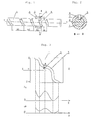
- the self-adapting screw transmission mechanism with variable lead comprises a screw with variable lead (1) and a nut (2), wherein, the screw (1) is a screw with variable lead, with lead H1, lead H2, lead H3, and lead H4 arranged on it; the screw groove (5) of the screw (1) is rectangular.
- the nut (2) comprises a sliding sleeve (4) and a pin (3), wherein the pin (3) protrudes from the inner surface of the sliding sleeve (4).
- the width of pin (3) is smaller than the diameter of the screw groove (5) of the screw (1).
- the nut (2) is screwed with the screw with variable lead (1) to form a screw pair.
- the pin (3) In the self-adapting screw transmission mechanism with variable lead, the pin (3) relatively moves in the screw groove (5) of the screw with variable lead (1) to form a screw pair, and thereby implements transmission between power and movement.
- the pin (3) is connected to the sliding sleeve (4) through rigid connection, and the screw pair is in sliding friction.
- the lead of the screw is variable.
- the pin (3) couples with the screw groove (5) of the screw, and guides the sliding sleeve in the screw groove (5) to move along the track of the screw groove, so that the nut is self-adapted to the variable lead of the screw.
- the axial movement speed is higher; in the small lead segment H3, the axial movement is lower; if the lead of the small lead segment H4 is small enough (the pitch angle is less than the friction angle), the screw pair can be self-locked. That is to say, through the same screw pair transmission, variable-speed transmission, non-self-lock transmission, self-lock transmission, and their combinations can be implemented.
- Fig. 2 is a B-B sectional view of Fig. 1 . It is more clearly shown that the nut (2) comprises a pin (3) and a sliding sleeve (4), wherein, the pin (3) protrudes from the inner surface of the sliding sleeve (4) and is embedded in the screw groove (5).
- the screw groove (5) is rectangular.
- the mathematical model of the screw transmission with variable lead is shown in Fig. 3 , i.e., the screw with variable lead is expanded to a two-dimensional plane along its circumference.
- the screw groove of the screw with variable lead contacts with the pin through point contact (line contact); if the screw with variable lead (1) is the driving part, the pin will bear a driving moment M and the resulting force R; therefore, the driving force applied on the screw pair transfers power and movement through the contact point (line).
- the nut (2) can work with any screw with variable lead (1) to form a screw pair and thereby accomplish screw transmission with variable lead.
- the lead P of the screw varies along the axial line X-X of the screw; likewise, the pitch angle ⁇ of the screw varies along the axial line X-X of the screw.
- Fig. 4 shows another structure of the nut (2) of the present invention.
- the nut (2) comprises pins (3) and a sliding sleeve (4).
- the screw is double-end, bearings (6) are installed on the sliding sleeve (4), two pins (3) are mounted in the bearings (6) symmetrically and protrude from the inner surface of the sliding sleeve (4); the pins (3) are connected to the bearings (6) through rotatable connection, and the screw pair is in rolling friction.
Landscapes
- Engineering & Computer Science (AREA)
- General Engineering & Computer Science (AREA)
- Mechanical Engineering (AREA)
- Transmission Devices (AREA)
Applications Claiming Priority (2)
| Application Number | Priority Date | Filing Date | Title |
|---|---|---|---|
| CNB2006100968272A CN100356088C (zh) | 2006-10-19 | 2006-10-19 | 自适应变导程螺旋传动机构 |
| PCT/CN2007/002851 WO2008046294A1 (fr) | 2006-10-19 | 2007-09-29 | Mécanisme de transmissions à vis auto-adaptative à filet variable |
Publications (2)
| Publication Number | Publication Date |
|---|---|
| EP2075488A1 true EP2075488A1 (de) | 2009-07-01 |
| EP2075488A4 EP2075488A4 (de) | 2009-11-25 |
Family
ID=38044592
Family Applications (1)
| Application Number | Title | Priority Date | Filing Date |
|---|---|---|---|
| EP07816465A Withdrawn EP2075488A4 (de) | 2006-10-19 | 2007-09-29 | Selbstanpassender schraubenübertragungsmechanismus mit variabler führung |
Country Status (3)
| Country | Link |
|---|---|
| EP (1) | EP2075488A4 (de) |
| CN (1) | CN100356088C (de) |
| WO (1) | WO2008046294A1 (de) |
Cited By (7)
| Publication number | Priority date | Publication date | Assignee | Title |
|---|---|---|---|---|
| WO2010034542A1 (de) * | 2008-09-23 | 2010-04-01 | Robert Bosch Gmbh | Schraubgetriebe |
| ITVR20120033A1 (it) * | 2012-02-28 | 2013-08-29 | Horvath Ildiko | Accoppiamento vite madrevite |
| EP3006973A1 (de) * | 2014-10-06 | 2016-04-13 | Sick Ag | Fokusverstellvorrichtung für ein Bilderfassungssystem |
| EP3388715A1 (de) * | 2017-04-12 | 2018-10-17 | Goodrich Actuation Systems Limited | Linearer aktuator |
| EP3489547A1 (de) * | 2017-11-27 | 2019-05-29 | Rohr, Inc. | Kinematisches system mit bewegungssteuerungsvorrichtung |
| WO2020070273A1 (de) * | 2018-10-04 | 2020-04-09 | Igus Gmbh | Spindelgetriebe |
| EP3725449A4 (de) * | 2019-02-26 | 2021-03-31 | Dengensha Toa Co., Ltd. | Druckvorrichtung und schweissvorrichtung |
Families Citing this family (6)
| Publication number | Priority date | Publication date | Assignee | Title |
|---|---|---|---|---|
| CN101761623B (zh) * | 2009-11-16 | 2011-09-14 | 江苏速升自动化装备系统工程有限公司 | 一个方向滚动另一方向滑动的组合螺旋副 |
| CN106594212B (zh) * | 2017-01-18 | 2023-09-29 | 南京理工大学 | 一种用于变导程丝杆的双滚子螺旋副装置 |
| CN108488343B (zh) * | 2018-03-23 | 2020-07-31 | 南京理工大学 | 一种基于电磁力平衡的高寿命变导程螺旋机构 |
| CN115076264B (zh) * | 2021-03-16 | 2024-06-18 | 陕西国力信息技术有限公司 | 一种导程可变的运动转换机构及电子机械制动器 |
| CN113853973B (zh) * | 2021-11-23 | 2023-11-28 | 中海海洋(厦门)市政工程发展有限公司 | 一种园林绿化枝干枝叶形状美化修剪装置 |
| CN121594109A (zh) * | 2024-08-20 | 2026-03-03 | 布雷博(南京)汽车零部件有限公司 | 用于盘式制动器的致动装置和盘式制动器 |
Family Cites Families (13)
| Publication number | Priority date | Publication date | Assignee | Title |
|---|---|---|---|---|
| US3779094A (en) * | 1972-06-12 | 1973-12-18 | Norco Inc | Reversing nut for a diamond thread screw |
| US4008625A (en) * | 1975-12-15 | 1977-02-22 | Norco, Inc. | Floating nut construction |
| DE2924457C2 (de) * | 1979-06-18 | 1987-03-19 | Rathgeber AG, 8000 München | Antrieb zum Betätigen von Türen |
| US4410067A (en) * | 1981-09-30 | 1983-10-18 | Otis Elevator Company | Elevator door operator |
| CN2106939U (zh) * | 1991-08-05 | 1992-06-10 | 邓隽钧 | 换向型滚动螺旋副 |
| US5320143A (en) * | 1992-08-14 | 1994-06-14 | National Science Council | Variable pitch cylindrical cam mechanism for controlling the motion of weft insertion members in shuttleless weaving looms |
| US5680795A (en) * | 1995-07-05 | 1997-10-28 | Norco Inc. | Mechanical drive assembly incorporating counter-spring biassed radially-adjustable rollers |
| CN1136149A (zh) * | 1995-10-09 | 1996-11-20 | 王克华 | 异形浮动螺旋动力密封装置 |
| JPH11129919A (ja) * | 1997-10-31 | 1999-05-18 | Toyota Motor Corp | 電動式パワーステアリング装置 |
| JP2000291770A (ja) * | 1999-04-01 | 2000-10-20 | Ntn Corp | ボールねじ |
| CN2487921Y (zh) * | 2001-06-18 | 2002-04-24 | 刘兴荣 | 半啮合滚动螺旋付 |
| JP3548138B2 (ja) * | 2001-07-11 | 2004-07-28 | ミネベア株式会社 | リニアアクチェータ用のリードスクリュー |
| CN100348832C (zh) * | 2006-10-18 | 2007-11-14 | 南京康尼机电新技术有限公司 | 无源螺旋门机锁闭机构 |
-
2006
- 2006-10-19 CN CNB2006100968272A patent/CN100356088C/zh active Active
-
2007
- 2007-09-29 EP EP07816465A patent/EP2075488A4/de not_active Withdrawn
- 2007-09-29 WO PCT/CN2007/002851 patent/WO2008046294A1/zh not_active Ceased
Cited By (17)
| Publication number | Priority date | Publication date | Assignee | Title |
|---|---|---|---|---|
| WO2010034542A1 (de) * | 2008-09-23 | 2010-04-01 | Robert Bosch Gmbh | Schraubgetriebe |
| KR20110059625A (ko) * | 2008-09-23 | 2011-06-02 | 로베르트 보쉬 게엠베하 | 헬리컬 기어장치 |
| ITVR20120033A1 (it) * | 2012-02-28 | 2013-08-29 | Horvath Ildiko | Accoppiamento vite madrevite |
| WO2013128372A1 (en) * | 2012-02-28 | 2013-09-06 | Horvath, Ildiko | Screw-nut assembly with rolling elements |
| EP3006973A1 (de) * | 2014-10-06 | 2016-04-13 | Sick Ag | Fokusverstellvorrichtung für ein Bilderfassungssystem |
| US9804356B2 (en) * | 2014-10-06 | 2017-10-31 | Sick Ag | Focus adjustment apparatus for an image detection system |
| EP3591262A1 (de) * | 2017-04-12 | 2020-01-08 | Goodrich Actuation Systems Limited | Linearer aktuator |
| EP3388715A1 (de) * | 2017-04-12 | 2018-10-17 | Goodrich Actuation Systems Limited | Linearer aktuator |
| US11359704B2 (en) | 2017-04-12 | 2022-06-14 | Goodrich Actuation Systems Limited | Linear actuator |
| US11639747B2 (en) | 2017-04-12 | 2023-05-02 | Goodrich Actuation Systems Limited | Linear actuator |
| EP3489547A1 (de) * | 2017-11-27 | 2019-05-29 | Rohr, Inc. | Kinematisches system mit bewegungssteuerungsvorrichtung |
| US10731738B2 (en) | 2017-11-27 | 2020-08-04 | Rohr, Inc. | Kinematic system with motion control device |
| WO2020070273A1 (de) * | 2018-10-04 | 2020-04-09 | Igus Gmbh | Spindelgetriebe |
| CN113366246A (zh) * | 2018-10-04 | 2021-09-07 | 易格斯有限公司 | 丝杠传动装置 |
| US11635127B2 (en) | 2018-10-04 | 2023-04-25 | Igus Gmbh | Spindle gear |
| CN113366246B (zh) * | 2018-10-04 | 2024-07-30 | 易格斯有限公司 | 丝杠传动装置 |
| EP3725449A4 (de) * | 2019-02-26 | 2021-03-31 | Dengensha Toa Co., Ltd. | Druckvorrichtung und schweissvorrichtung |
Also Published As
| Publication number | Publication date |
|---|---|
| EP2075488A4 (de) | 2009-11-25 |
| WO2008046294A1 (fr) | 2008-04-24 |
| CN100356088C (zh) | 2007-12-19 |
| CN1945055A (zh) | 2007-04-11 |
Similar Documents
| Publication | Publication Date | Title |
|---|---|---|
| WO2008046294A1 (fr) | Mécanisme de transmissions à vis auto-adaptative à filet variable | |
| US3053105A (en) | Anti-friction screw device | |
| CN113530917B (zh) | 一种数字液压缸 | |
| CN103541943B (zh) | 一种可旋转并联控制的大流量高频响数字阀 | |
| CN103453096B (zh) | 一种能实现微小导程的滚柱丝杠副 | |
| CN103499927A (zh) | 一种直流伺服电机位置控制系统 | |
| US4898044A (en) | Cam-driven linear actuator apparatus | |
| CN107336261A (zh) | 一种变距机构 | |
| US4199999A (en) | Ball-type mechanical transmission | |
| US4337671A (en) | Apparatus for translating rotary movement to rectilinear movement | |
| CN205503895U (zh) | 一种限制丝杠螺母旋转的装置 | |
| CN205315617U (zh) | 滚珠丝杠蜗轮减速器 | |
| CN202048152U (zh) | 一种行星滚柱丝杠 | |
| CN105443661A (zh) | 滚珠丝杠蜗轮减速器 | |
| JP2012067899A (ja) | 増減速機 | |
| CN204239649U (zh) | 滚珠丝杠 | |
| CN106986148A (zh) | 两个滚轮构成一个滑块的导轨装置 | |
| CN216951524U (zh) | 一种反向双螺旋往返机构 | |
| CN215861073U (zh) | 一种数字液压缸 | |
| KR101478061B1 (ko) | 너트 스크류 이송장치 | |
| Wu et al. | Disk cam mechanisms with a translating follower having symmetrical double rollers | |
| CN108019479B (zh) | 一种机电作动器滑槽式导向齿限位导向装置 | |
| CN116604360B (zh) | 一种高速传动的螺旋导轨副 | |
| CN120083801B (zh) | 一种具有双向锚定双层行星滚柱丝杠结构的两级作动器 | |
| SE514794C2 (sv) | Pneumatiskt eller hydrauliskt manöverdon |
Legal Events
| Date | Code | Title | Description |
|---|---|---|---|
| PUAI | Public reference made under article 153(3) epc to a published international application that has entered the european phase |
Free format text: ORIGINAL CODE: 0009012 |
|
| 17P | Request for examination filed |
Effective date: 20081120 |
|
| AK | Designated contracting states |
Kind code of ref document: A1 Designated state(s): AT BE BG CH CY CZ DE DK EE ES FI FR GB GR HU IE IS IT LI LT LU LV MC MT NL PL PT RO SE SI SK TR |
|
| AX | Request for extension of the european patent |
Extension state: AL BA HR MK RS |
|
| A4 | Supplementary search report drawn up and despatched |
Effective date: 20091023 |
|
| 17Q | First examination report despatched |
Effective date: 20100209 |
|
| STAA | Information on the status of an ep patent application or granted ep patent |
Free format text: STATUS: THE APPLICATION IS DEEMED TO BE WITHDRAWN |
|
| 18D | Application deemed to be withdrawn |
Effective date: 20100622 |