EP2075506A2 - Habillage de chambre de combustion - Google Patents
Habillage de chambre de combustion Download PDFInfo
- Publication number
- EP2075506A2 EP2075506A2 EP08021918A EP08021918A EP2075506A2 EP 2075506 A2 EP2075506 A2 EP 2075506A2 EP 08021918 A EP08021918 A EP 08021918A EP 08021918 A EP08021918 A EP 08021918A EP 2075506 A2 EP2075506 A2 EP 2075506A2
- Authority
- EP
- European Patent Office
- Prior art keywords
- combustion chamber
- ceramic
- metallic
- cooling air
- hollow body
- Prior art date
- Legal status (The legal status is an assumption and is not a legal conclusion. Google has not performed a legal analysis and makes no representation as to the accuracy of the status listed.)
- Granted
Links
Images

Classifications
-
- F—MECHANICAL ENGINEERING; LIGHTING; HEATING; WEAPONS; BLASTING
- F23—COMBUSTION APPARATUS; COMBUSTION PROCESSES
- F23R—GENERATING COMBUSTION PRODUCTS OF HIGH PRESSURE OR HIGH VELOCITY, e.g. GAS-TURBINE COMBUSTION CHAMBERS
- F23R3/00—Continuous combustion chambers using liquid or gaseous fuel
- F23R3/002—Wall structures
-
- F—MECHANICAL ENGINEERING; LIGHTING; HEATING; WEAPONS; BLASTING
- F23—COMBUSTION APPARATUS; COMBUSTION PROCESSES
- F23R—GENERATING COMBUSTION PRODUCTS OF HIGH PRESSURE OR HIGH VELOCITY, e.g. GAS-TURBINE COMBUSTION CHAMBERS
- F23R3/00—Continuous combustion chambers using liquid or gaseous fuel
- F23R3/007—Continuous combustion chambers using liquid or gaseous fuel constructed mainly of ceramic components
-
- F—MECHANICAL ENGINEERING; LIGHTING; HEATING; WEAPONS; BLASTING
- F23—COMBUSTION APPARATUS; COMBUSTION PROCESSES
- F23R—GENERATING COMBUSTION PRODUCTS OF HIGH PRESSURE OR HIGH VELOCITY, e.g. GAS-TURBINE COMBUSTION CHAMBERS
- F23R3/00—Continuous combustion chambers using liquid or gaseous fuel
- F23R3/02—Continuous combustion chambers using liquid or gaseous fuel characterised by the air-flow or gas-flow configuration
- F23R3/04—Air inlet arrangements
- F23R3/06—Arrangement of apertures along the flame tube
-
- F—MECHANICAL ENGINEERING; LIGHTING; HEATING; WEAPONS; BLASTING
- F23—COMBUSTION APPARATUS; COMBUSTION PROCESSES
- F23R—GENERATING COMBUSTION PRODUCTS OF HIGH PRESSURE OR HIGH VELOCITY, e.g. GAS-TURBINE COMBUSTION CHAMBERS
- F23R2900/00—Special features of, or arrangements for continuous combustion chambers; Combustion processes therefor
- F23R2900/03041—Effusion cooled combustion chamber walls or domes
-
- F—MECHANICAL ENGINEERING; LIGHTING; HEATING; WEAPONS; BLASTING
- F23—COMBUSTION APPARATUS; COMBUSTION PROCESSES
- F23R—GENERATING COMBUSTION PRODUCTS OF HIGH PRESSURE OR HIGH VELOCITY, e.g. GAS-TURBINE COMBUSTION CHAMBERS
- F23R2900/00—Special features of, or arrangements for continuous combustion chambers; Combustion processes therefor
- F23R2900/03042—Film cooled combustion chamber walls or domes
-
- F—MECHANICAL ENGINEERING; LIGHTING; HEATING; WEAPONS; BLASTING
- F23—COMBUSTION APPARATUS; COMBUSTION PROCESSES
- F23R—GENERATING COMBUSTION PRODUCTS OF HIGH PRESSURE OR HIGH VELOCITY, e.g. GAS-TURBINE COMBUSTION CHAMBERS
- F23R2900/00—Special features of, or arrangements for continuous combustion chambers; Combustion processes therefor
- F23R2900/03044—Impingement cooled combustion chamber walls or subassemblies
Definitions
- the invention relates to a combustion chamber for a gas turbine according to the features of the preamble of claim 1.
- the invention relates to a combustion chamber for a gas turbine with a metallic support structure and with a plurality of distributed circumferentially arranged ceramic hollow profiles, which are fixed to the support structure.
- This prior art is from the DE 195 02 730 A1 previously known.
- the DE 195 02 730 A1 describes the ceramic lining of a combustion chamber with at least one uncooled wall plate, which consists of high-temperature-resistant structural ceramic and which is connected by means of a fastening element resiliently to a holding device.
- the bonding surface between the fastener and the ceramic is shaped to provide minimal thermal stress.
- the disadvantage is that only a convective cooling of the metallic wall is possible, which requires a high cooling air mass flow.
- the fastener rests on the side facing the hot gas side and is thus exposed to elevated thermal loads.
- the EP 0 943 867 B1 describes the ceramic lining of a combustion chamber with individual juxtaposed segments in the form of hollow chambers, which can also serve for flow guidance.
- the ceramic lining can be fixed on the side facing the metallic structure.
- the cavity can also be provided for cooling guidance and thus achieves higher Heat transfer rates; but this cooling technology is limited only to a convective cooling of the ceramic wall element directed towards the internal combustion chamber. Furthermore, it is not apparent how a dosage of the cooling air takes place and also a control of the local cooling mass flows in the continuous cavity is considered difficult. Another disadvantage is that the entire axial length is made in one piece. The result is that kinks must be mitgefertigt in one piece.
- the invention has for its object to provide a combustion chamber of the type mentioned for a gas turbine, which is inexpensive to produce with a simple structure and simple, reliable operation and avoids the disadvantages of the prior art.
- the ceramic, tubular hollow profiles are each formed in a straight line and are arranged as individual segments.
- a metallic hollow body is arranged, which is preferably formed in the form of a hollow box.
- On at least one wall air passage openings are provided on the metallic hollow body, which may be formed in the form of a perforation. Through this air passage openings escapes cooling air, which is introduced into the metallic hollow body.
- the metallic hollow body is preferably arranged to form a gap in the ceramic hollow profile, so that the cooling air flowing through the air passage openings can be distributed in the ceramic hollow profile.
- the ceramic hollow profile may preferably be provided on its wall facing a combustion chamber with additional air passage openings.
- the air passage openings (perforation) of the metallic hollow body are preferably formed on the combustion chamber interior facing wall to ensure effective cooling of the ceramic hollow profile.
- the metallic hollow body is preferably connected by means of a cooling air supply line to a cooling air system. Thus, cooling air leaks are avoided.
- the ceramic hollow profile is formed as a straight profile and when several such ceramic hollow sections are arranged segment-like on the wall of the combustion chamber to form the curved contour of the combustion chamber is particularly favorable.
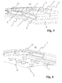
- a metallic support structure 6 with segmented in the circumferential and axial direction ceramic tubular hollow sections 2, which can be produced from a section of a straight profile.
- a one-sided perforated, air-flow, metallic hollow box 1 which is fastened by means of one or more fasteners 7 together with the ceramic hollow section 2 on the metallic support 6.
- cooling air supply line 8 in the metallic support 6, the ceramic hollow sections 2 and the metallic hollow box 1 is provided, which is as close as possible to a fastener on this and several as centrally located between them.
- the hollow box through which the cooling air flows serves to control the cooling air.
- the air passage openings (perforation) 5 which indicates the flow-determining surface, a suitable amount of cooling air in the corresponding area provided for the ceramic hollow profile 2 can be adjusted. Because the metallic hollow box is completed and has only a cooling air supply line 8 and the air passage openings 5, no leakage currents occur.
- the cooling air that emerges from the metallic hollow box bounces on the back of the ceramic lining 3 and thus significantly increases the heat transfer.
- the air escapes thereafter at the ends of the ceramic hollow profile and, due to the axial segmentation, can serve for film cooling of the ceramic surface facing the hot gas, but also for protecting the metallic structure from hot gas penetration into the intermediate gaps.
- a perforation of the hot gas side ceramic surface 9 is advantageous.
- the one-sided perforated, air-flow, metallic hollow box allows a controlled cooling air distribution in the combustion chamber wall. There are no parasitic leakage currents. Through the perforation of the hollow box, the back of the ceramic surface facing the combustion chamber can be cooled tightly. As a result, the heat flow from the wall is significantly increased. By an additional perforation of the ceramic surface, the cooling effect can be increased again. If the holes for cooling air supply positioned as close as possible to the fasteners, no leakage currents can occur along the gaps between the individual components.
- the segmented structure makes it possible to produce universally applicable ceramic components that can be used in combustion chambers of any size and shape.
Landscapes
- Engineering & Computer Science (AREA)
- Chemical & Material Sciences (AREA)
- Combustion & Propulsion (AREA)
- Mechanical Engineering (AREA)
- General Engineering & Computer Science (AREA)
- Ceramic Engineering (AREA)
- Turbine Rotor Nozzle Sealing (AREA)
Applications Claiming Priority (1)
| Application Number | Priority Date | Filing Date | Title |
|---|---|---|---|
| DE102007062699A DE102007062699A1 (de) | 2007-12-27 | 2007-12-27 | Brennkammerauskleidung |
Publications (3)
| Publication Number | Publication Date |
|---|---|
| EP2075506A2 true EP2075506A2 (fr) | 2009-07-01 |
| EP2075506A3 EP2075506A3 (fr) | 2014-11-12 |
| EP2075506B1 EP2075506B1 (fr) | 2016-04-27 |
Family
ID=40482017
Family Applications (1)
| Application Number | Title | Priority Date | Filing Date |
|---|---|---|---|
| EP08021918.1A Not-in-force EP2075506B1 (fr) | 2007-12-27 | 2008-12-17 | Habillage de chambre de combustion |
Country Status (3)
| Country | Link |
|---|---|
| US (1) | US8074453B2 (fr) |
| EP (1) | EP2075506B1 (fr) |
| DE (1) | DE102007062699A1 (fr) |
Cited By (1)
| Publication number | Priority date | Publication date | Assignee | Title |
|---|---|---|---|---|
| CN115930259A (zh) * | 2023-01-31 | 2023-04-07 | 上海电气燃气轮机有限公司 | 一种燃气轮机燃烧室的隔热瓦及热屏 |
Families Citing this family (4)
| Publication number | Priority date | Publication date | Assignee | Title |
|---|---|---|---|---|
| DE102012213637A1 (de) * | 2012-08-02 | 2014-02-06 | Siemens Aktiengesellschaft | Brennkammerkühlung |
| WO2014149108A1 (fr) | 2013-03-15 | 2014-09-25 | Graves Charles B | Agencement d'enceinte et de chemisage à dalles pour une chambre de combustion |
| WO2015009384A1 (fr) | 2013-07-16 | 2015-01-22 | United Technologies Corporation | Turbine à gaz pourvue d'un panneau en céramique |
| US10815638B2 (en) * | 2013-10-17 | 2020-10-27 | Joy Global Surface Mining Inc | Liner system for a dipper |
Citations (3)
| Publication number | Priority date | Publication date | Assignee | Title |
|---|---|---|---|---|
| US4512699A (en) | 1983-05-17 | 1985-04-23 | The United States Of America As Represented By The Administrator Of The National Aeronautics And Space Administration | Daze fasteners |
| DE19502730A1 (de) | 1995-01-28 | 1996-08-01 | Abb Management Ag | Keramische Auskleidung |
| EP0943867B1 (fr) | 1998-03-17 | 2002-12-18 | ALSTOM (Switzerland) Ltd | Revêtement céramique pour une chambre de combustion |
Family Cites Families (15)
| Publication number | Priority date | Publication date | Assignee | Title |
|---|---|---|---|---|
| US3956886A (en) * | 1973-12-07 | 1976-05-18 | Joseph Lucas (Industries) Limited | Flame tubes for gas turbine engines |
| US4269032A (en) * | 1979-06-13 | 1981-05-26 | General Motors Corporation | Waffle pattern porous material |
| US4838031A (en) * | 1987-08-06 | 1989-06-13 | Avco Corporation | Internally cooled combustion chamber liner |
| WO1989012789A1 (fr) * | 1988-06-13 | 1989-12-28 | Siemens Aktiengesellschaft | Bouclier thermique n'exigeant que peu de fluide de refroidissement |
| DE19730751A1 (de) * | 1996-07-24 | 1998-01-29 | Siemens Ag | Keramisches Bauteil für eine Wärmeschutzschicht sowie Wärmeschutzschicht |
| DE59706065D1 (de) * | 1996-09-26 | 2002-02-21 | Siemens Ag | Hitzeschildkomponente mit kühlfluidrückführung und hitzeschildanordnung für eine heissgasführende komponente |
| DE19727407A1 (de) * | 1997-06-27 | 1999-01-07 | Siemens Ag | Hitzeschild |
| DE29714742U1 (de) * | 1997-08-18 | 1998-12-17 | Siemens AG, 80333 München | Hitzeschildkomponente mit Kühlfluidrückführung und Hitzeschildanordnung für eine heißgasführende Komponente |
| FR2777634B1 (fr) * | 1998-04-16 | 2000-05-19 | Snecma | Separateur pour chambre de combustion a deux tetes |
| DE10003728A1 (de) * | 2000-01-28 | 2001-08-09 | Siemens Ag | Hitzeschildanordnung für eine Heißgas führende Komponente, insbesondere für Strukturteile von Gasturbinen |
| US6514046B1 (en) * | 2000-09-29 | 2003-02-04 | Siemens Westinghouse Power Corporation | Ceramic composite vane with metallic substructure |
| EP1271056A1 (fr) * | 2001-06-20 | 2003-01-02 | Siemens Aktiengesellschaft | Chambre de combustion de turbine à gaz et méthode pour y amener de l'air |
| EP1284390A1 (fr) * | 2001-06-27 | 2003-02-19 | Siemens Aktiengesellschaft | Ensemble bouclier thermique pour un composant acheminant un gaz chaud, notamment pour des pièces de structure de turbines à gaz |
| EP1431661A1 (fr) * | 2002-12-19 | 2004-06-23 | Siemens Aktiengesellschaft | Corps de guidage d'écoulement |
| US7908867B2 (en) * | 2007-09-14 | 2011-03-22 | Siemens Energy, Inc. | Wavy CMC wall hybrid ceramic apparatus |
-
2007
- 2007-12-27 DE DE102007062699A patent/DE102007062699A1/de not_active Withdrawn
-
2008
- 2008-12-17 EP EP08021918.1A patent/EP2075506B1/fr not_active Not-in-force
- 2008-12-23 US US12/318,259 patent/US8074453B2/en not_active Expired - Fee Related
Patent Citations (3)
| Publication number | Priority date | Publication date | Assignee | Title |
|---|---|---|---|---|
| US4512699A (en) | 1983-05-17 | 1985-04-23 | The United States Of America As Represented By The Administrator Of The National Aeronautics And Space Administration | Daze fasteners |
| DE19502730A1 (de) | 1995-01-28 | 1996-08-01 | Abb Management Ag | Keramische Auskleidung |
| EP0943867B1 (fr) | 1998-03-17 | 2002-12-18 | ALSTOM (Switzerland) Ltd | Revêtement céramique pour une chambre de combustion |
Cited By (1)
| Publication number | Priority date | Publication date | Assignee | Title |
|---|---|---|---|---|
| CN115930259A (zh) * | 2023-01-31 | 2023-04-07 | 上海电气燃气轮机有限公司 | 一种燃气轮机燃烧室的隔热瓦及热屏 |
Also Published As
| Publication number | Publication date |
|---|---|
| US20090193810A1 (en) | 2009-08-06 |
| DE102007062699A1 (de) | 2009-07-02 |
| US8074453B2 (en) | 2011-12-13 |
| EP2075506B1 (fr) | 2016-04-27 |
| EP2075506A3 (fr) | 2014-11-12 |
Similar Documents
| Publication | Publication Date | Title |
|---|---|---|
| EP1193451B1 (fr) | Tête de chambre de combustion d'une turbine à gaz | |
| EP0309838B1 (fr) | Brûleur à gaz | |
| EP2423599B1 (fr) | Procédé de fonctionnement d'un agencement de brûleur ainsi qu'agencement de brûleur destiné à la mise en oeuvre du procédé | |
| DE874680C (de) | Duesenkasten fuer Gasturbinentriebwerke | |
| EP2049840B1 (fr) | Chambre de combustion d'une installation de combustion | |
| EP2075506B1 (fr) | Habillage de chambre de combustion | |
| WO2008017551A2 (fr) | Chambre de combustion d'une installation d'incinération | |
| EP2011965A2 (fr) | Dispositif et procédé pour serrer des disques de rotor portant des aubes d'un moteur à réaction | |
| DE3346809A1 (de) | Axialsymmetrische schubduese mit veraenderbarer querschnittsflaeche | |
| DE102006026969A1 (de) | Gasturbinenbrennkammerwand für eine mager-brennende Gasturbinenbrennkammer | |
| EP2574731A2 (fr) | Composant segmenté | |
| EP1860295A2 (fr) | Installation de gaz d'échappement | |
| EP1429001A2 (fr) | Silencieux d'admission pour turbines à gaz | |
| EP0574605A1 (fr) | Filtre-amortisseur de bruit | |
| EP3117148B1 (fr) | Système de combustion avec résonateur | |
| EP1778953B1 (fr) | Dispositif de nettoyage de turbine | |
| EP2883003B1 (fr) | Bouclier thermique comportant une structure support et procédé de refroidissement de la structure support | |
| DE1291554B (de) | Brennkammer fuer Gasturbinen | |
| DE1132002B (de) | Vorzugsweise als Nachbrenner ausgebildete Austrittsduese fuer ein Flugzeugtriebwerksbuendel | |
| DE3535442C2 (fr) | ||
| EP0981016B1 (fr) | Brûleur pour le fonctionnement d'une chambre de combustion | |
| EP1422479B1 (fr) | Chambre pour la combustion d' un mélange combustible fluide | |
| DE19538364C5 (de) | Vorrichtung zur Schnellerwärmung von Metall-Preßbolzen | |
| EP1512911A1 (fr) | Arrangement pour refroidir des éléments soumis à de fortes contraintes thermiques | |
| DE4100225C2 (fr) |
Legal Events
| Date | Code | Title | Description |
|---|---|---|---|
| PUAI | Public reference made under article 153(3) epc to a published international application that has entered the european phase |
Free format text: ORIGINAL CODE: 0009012 |
|
| AK | Designated contracting states |
Kind code of ref document: A2 Designated state(s): AT BE BG CH CY CZ DE DK EE ES FI FR GB GR HR HU IE IS IT LI LT LU LV MC MT NL NO PL PT RO SE SI SK TR |
|
| AX | Request for extension of the european patent |
Extension state: AL BA MK RS |
|
| PUAL | Search report despatched |
Free format text: ORIGINAL CODE: 0009013 |
|
| AK | Designated contracting states |
Kind code of ref document: A3 Designated state(s): AT BE BG CH CY CZ DE DK EE ES FI FR GB GR HR HU IE IS IT LI LT LU LV MC MT NL NO PL PT RO SE SI SK TR |
|
| AX | Request for extension of the european patent |
Extension state: AL BA MK RS |
|
| RIC1 | Information provided on ipc code assigned before grant |
Ipc: F23R 3/06 20060101ALI20141007BHEP Ipc: F23R 3/00 20060101AFI20141007BHEP |
|
| 17P | Request for examination filed |
Effective date: 20150129 |
|
| RBV | Designated contracting states (corrected) |
Designated state(s): AT BE BG CH CY CZ DE DK EE ES FI FR GB GR HR HU IE IS IT LI LT LU LV MC MT NL NO PL PT RO SE SI SK TR |
|
| AKX | Designation fees paid |
Designated state(s): DE FR GB |
|
| AXX | Extension fees paid |
Extension state: AL Extension state: RS Extension state: BA Extension state: MK |
|
| GRAP | Despatch of communication of intention to grant a patent |
Free format text: ORIGINAL CODE: EPIDOSNIGR1 |
|
| INTG | Intention to grant announced |
Effective date: 20151028 |
|
| GRAS | Grant fee paid |
Free format text: ORIGINAL CODE: EPIDOSNIGR3 |
|
| GRAA | (expected) grant |
Free format text: ORIGINAL CODE: 0009210 |
|
| RIN1 | Information on inventor provided before grant (corrected) |
Inventor name: SADIG, SERMED Inventor name: GERENDAS, MIKLOS, DR. |
|
| AK | Designated contracting states |
Kind code of ref document: B1 Designated state(s): DE FR GB |
|
| REG | Reference to a national code |
Ref country code: GB Ref legal event code: FG4D Free format text: NOT ENGLISH |
|
| REG | Reference to a national code |
Ref country code: DE Ref legal event code: R096 Ref document number: 502008014129 Country of ref document: DE |
|
| REG | Reference to a national code |
Ref country code: FR Ref legal event code: PLFP Year of fee payment: 9 |
|
| REG | Reference to a national code |
Ref country code: DE Ref legal event code: R097 Ref document number: 502008014129 Country of ref document: DE |
|
| PLBE | No opposition filed within time limit |
Free format text: ORIGINAL CODE: 0009261 |
|
| STAA | Information on the status of an ep patent application or granted ep patent |
Free format text: STATUS: NO OPPOSITION FILED WITHIN TIME LIMIT |
|
| 26N | No opposition filed |
Effective date: 20170130 |
|
| REG | Reference to a national code |
Ref country code: FR Ref legal event code: PLFP Year of fee payment: 10 |
|
| PGFP | Annual fee paid to national office [announced via postgrant information from national office to epo] |
Ref country code: FR Payment date: 20191226 Year of fee payment: 12 |
|
| PGFP | Annual fee paid to national office [announced via postgrant information from national office to epo] |
Ref country code: DE Payment date: 20191231 Year of fee payment: 12 Ref country code: GB Payment date: 20191227 Year of fee payment: 12 |
|
| REG | Reference to a national code |
Ref country code: DE Ref legal event code: R119 Ref document number: 502008014129 Country of ref document: DE |
|
| GBPC | Gb: european patent ceased through non-payment of renewal fee |
Effective date: 20201217 |
|
| PG25 | Lapsed in a contracting state [announced via postgrant information from national office to epo] |
Ref country code: FR Free format text: LAPSE BECAUSE OF NON-PAYMENT OF DUE FEES Effective date: 20201231 |
|
| PG25 | Lapsed in a contracting state [announced via postgrant information from national office to epo] |
Ref country code: DE Free format text: LAPSE BECAUSE OF NON-PAYMENT OF DUE FEES Effective date: 20210701 Ref country code: GB Free format text: LAPSE BECAUSE OF NON-PAYMENT OF DUE FEES Effective date: 20201217 |