EP2075529A2 - Procédé de mesure de forages - Google Patents
Procédé de mesure de forages Download PDFInfo
- Publication number
- EP2075529A2 EP2075529A2 EP08022286A EP08022286A EP2075529A2 EP 2075529 A2 EP2075529 A2 EP 2075529A2 EP 08022286 A EP08022286 A EP 08022286A EP 08022286 A EP08022286 A EP 08022286A EP 2075529 A2 EP2075529 A2 EP 2075529A2
- Authority
- EP
- European Patent Office
- Prior art keywords
- housing
- measuring
- bore
- measuring probe
- compressed air
- Prior art date
- Legal status (The legal status is an assumption and is not a legal conclusion. Google has not performed a legal analysis and makes no representation as to the accuracy of the status listed.)
- Withdrawn
Links
- 238000000034 method Methods 0.000 title description 3
- 239000000523 sample Substances 0.000 claims description 59
- 238000005259 measurement Methods 0.000 claims description 34
- 230000003287 optical effect Effects 0.000 claims description 8
- 238000003384 imaging method Methods 0.000 claims description 6
- 238000011156 evaluation Methods 0.000 claims description 5
- 238000012545 processing Methods 0.000 claims description 5
- 238000007789 sealing Methods 0.000 claims description 5
- 238000001514 detection method Methods 0.000 claims description 3
- 238000011511 automated evaluation Methods 0.000 claims description 2
- 238000007599 discharging Methods 0.000 claims 1
- 238000009423 ventilation Methods 0.000 claims 1
- 239000004020 conductor Substances 0.000 abstract 1
- 230000008719 thickening Effects 0.000 description 6
- 239000013307 optical fiber Substances 0.000 description 4
- 238000005452 bending Methods 0.000 description 2
- 238000012937 correction Methods 0.000 description 2
- 238000006073 displacement reaction Methods 0.000 description 2
- 230000002349 favourable effect Effects 0.000 description 2
- 238000002347 injection Methods 0.000 description 2
- 239000007924 injection Substances 0.000 description 2
- 238000003780 insertion Methods 0.000 description 2
- 230000037431 insertion Effects 0.000 description 2
- 238000007689 inspection Methods 0.000 description 2
- 238000012544 monitoring process Methods 0.000 description 2
- 230000000903 blocking effect Effects 0.000 description 1
- 238000009530 blood pressure measurement Methods 0.000 description 1
- 238000004364 calculation method Methods 0.000 description 1
- 238000004140 cleaning Methods 0.000 description 1
- 239000000356 contaminant Substances 0.000 description 1
- 230000002950 deficient Effects 0.000 description 1
- 238000013461 design Methods 0.000 description 1
- 238000005553 drilling Methods 0.000 description 1
- 230000000694 effects Effects 0.000 description 1
- 238000004519 manufacturing process Methods 0.000 description 1
- 238000000926 separation method Methods 0.000 description 1
- 230000035939 shock Effects 0.000 description 1
- 230000005236 sound signal Effects 0.000 description 1
- 230000002123 temporal effect Effects 0.000 description 1
- 238000012360 testing method Methods 0.000 description 1
- 238000011144 upstream manufacturing Methods 0.000 description 1
- 238000013022 venting Methods 0.000 description 1
Images




Classifications
-
- G—PHYSICS
- G01—MEASURING; TESTING
- G01B—MEASURING LENGTH, THICKNESS OR SIMILAR LINEAR DIMENSIONS; MEASURING ANGLES; MEASURING AREAS; MEASURING IRREGULARITIES OF SURFACES OR CONTOURS
- G01B13/00—Measuring arrangements characterised by the use of fluids
- G01B13/08—Measuring arrangements characterised by the use of fluids for measuring diameters
- G01B13/10—Measuring arrangements characterised by the use of fluids for measuring diameters internal diameters
-
- G—PHYSICS
- G01—MEASURING; TESTING
- G01B—MEASURING LENGTH, THICKNESS OR SIMILAR LINEAR DIMENSIONS; MEASURING ANGLES; MEASURING AREAS; MEASURING IRREGULARITIES OF SURFACES OR CONTOURS
- G01B5/00—Measuring arrangements characterised by the use of mechanical techniques
- G01B5/004—Measuring arrangements characterised by the use of mechanical techniques for measuring coordinates of points
- G01B5/008—Measuring arrangements characterised by the use of mechanical techniques for measuring coordinates of points using coordinate measuring machines
Definitions
- the principle of pneumatic length measurement is used, for example, in the quality inspection of injection nozzles for motor vehicles, whose fine channels are designed to produce injection pressures of 2000 bar and more and which require a diameter accuracy of less than 1 micron.
- the principle of the invention underlying the determination of the bore position in a housing opening is not limited to pneumatic measuring mandrels, but can be applied to any introduced into holes probes.
- the measuring probe comprises a compressed air supply channel and at least two air outlet nozzles.
- the compressed air supply channel can be supplied with compressed air via a supply line, which is passed through the wall of the housing.
- the air outlet nozzles are preferably located at an axial end of the measuring mandrel and point radially outward. Since the air flow rate through the compressed air supply passage in a defined manner depends on the distance between the bore wall and the respective air outlet nozzle, the diameter of the bore can be determined by a pressure or flow measurement.
- At least one O-ring may be provided around the outlet opening of the housing.
- two concentric O-rings are provided around the outlet opening of the housing.
- the O-rings may be located, for example, in correspondingly shaped grooves in the housing wall. They allow in a simple way a reliable sealing of the housing relative to the measuring object surface.
- a valve may be provided to selectively connect or disconnect the channel with the common compressed air supply. If the duct communicates not with the compressed air supply but only with the area between the O-rings, any leakage through a pressure drop in the duct can be detected. It can thus be continuously monitored during the measurement process, the pressure in the channel and thus in the area between the O-rings.
- an evaluation device is preferably provided, which is designed to output a warning signal when, with the valve in the disconnected position, a temporal change of the air pressure in the channel exceeds a predetermined threshold value.
- the valve before the measurement with the valve in the connection position, it can be checked whether the pressure in the channel deviates significantly from the supply pressure after a predetermined pressure build-up time. If this is not the case, so the seal is sufficient, the valve is placed in the disconnected position and the measuring process is started. The pressure of air trapped in the channel and the area between the O-rings is continuously monitored, and an undesirable high change, the operator of the measuring device is warned.
- an actuator can be arranged within the housing, by means of which the measuring probe is adjustable relative to the housing in at least one direction, in particular retractable and extendable.
- the housing may remain firmly at the location where it was once applied, while the probe is displaced to the location of the bore by the actuator relative to the housing.
- the actuator may, for example, be one or more piezo drive elements, preferably a 3D piezo positioning system. In conjunction with the means for determining the position of the bore, such an actuator can even ensure fully automatic positioning of the measuring probe.
- an imaging sensor in particular a camera or a CCD chip, is provided for position detection.
- a sensor can quickly and reliably detect the position of a bore within the exit port and either display it on a display or forward it for processing.
- the outlet opening of the housing has a curvature adapted to a predefined measurement object shape.
- By adjusting the shape of the outlet opening bores can be measured in measurement objects with arbitrarily shaped surface in principle.
- a bypass nozzle can be provided parallel to a compressed air line opening out in the interior of the housing for the measuring probe.
- a bypass nozzle By means of such a bypass nozzle, a defined amount of air per unit of time can be discharged outside the measuring device. As a result, the total air flow of the device can be increased in order to achieve a favorable operating point with respect to a supply pressure characteristic.
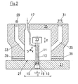
- the measuring mandrel 11 is attached to an actuator 23, which in turn is connected to a bell-shaped housing 25, so that the housing 25 surrounds the measuring mandrel 11 and the actuator 23 to an outlet opening 27.
- the actuator 23 By means of the actuator 23, the measuring mandrel 11 is displaceable relative to the housing 25.
- the actuator is formed in the example shown as a three-axis piezo positioning.
- the measuring mandrel 11 can be retracted in a Z-direction in the housing 25 so that it does not protrude from the outlet opening 27, or it can be extended for measurement in a bore 19.
- the measuring mandrel 11 can be displaced perpendicular to the Z-direction in an X-direction and a Y-direction parallel to the plane of the outlet opening 27. How out Fig. 1 shows, the diameter B of the outlet opening 27 by a multiple larger than the diameter D of the bore 19th
- a light source 29 and a camera 31 is provided outside the housing 25, a light source 29 and a camera 31 is provided outside the housing 25, a light source 29 and a camera 31 is provided.
- An optical fiber 33 passes through the wall of the housing 25 and transmits light (shown by arrows) from the light source 29 in the interior of the housing 25, so that the area of the surface of the measuring object 21, which is located at the outlet opening 27, is illuminated.
- an optical waveguide 35 is provided, which passes through the wall of the housing 25 and transmits an image of the interior of the housing 25 to the camera 31.
- one or more endoscope optical waveguides can also be used.
- the position of the bore 19 can be displayed to an operator of the device.
- This display can be used to prevent further movement of the housing 25 from this point in time. This is advantageous in particular with manual actuation of the measuring device, wherein the display can then take place via a lamp and / or via a sound signal.
- a warning signal is issued or a control unit, not shown, ensures that no measuring operation can be started. In this way it is prevented that the measuring mandrel 11 is moved against the surface of the measuring object 21 and thereby damaged.
- the camera image in an evaluation device also not shown, can be automatically evaluated by means of suitable image processing algorithms in various ways known in the art.
- one or more ports for providing blown air may be provided on the housing 25.
- the effluent from the air outlet nozzles 15 measuring air can at the in Fig. 1 discharged measuring condition through the bore 19 to the outside. However, this possibility is eliminated when measuring blind holes.
- blind holes With the in Fig. 2 Also shown blind holes can be measured, since transverse to the housing wall extending vent channels 39 are provided. The vent channels 39 can of course also be arranged elsewhere than in Fig. 2 shown.
- the device of Fig. 3 includes a compressed air supply 41 and a compressed air line 69, which opens in the interior of the housing 25. Further, an O-ring 43 is provided around the outlet opening 27 of the housing 25, which seals the outlet opening 27 against the surface of the measuring object 21. Instead of the measuring mandrel 11, a measuring needle 45 is attached to the actuator 23. At the end of the measuring needle 45 facing away from the actuator 23, a thickening 47 is formed.
- Fig. 3 The use of the device according to Fig. 3 is done in a similar way as in relation to Fig. 1 described, wherein the thickening 47 generates a constriction or restriction 49 in the bore 19 to be measured, which obstructs an air flow through the bore 19 in dependence on the bore diameter D. Since the compressed air supplied by the compressed air supply 41 compressed air due to the seal through the O-ring 43 can flow only through the bore 19 and consequently through the restrictor 49, can again determine a measurement of the current flow or pressure, the diameter D of the bore 19.
- the advantage here is in particular the easier manufacturability of the channelless measuring needle 45 with respect to a pneumatic measuring mandrel 11 with a central measuring channel.
- conventional pneumatic metering mandrels generally can not be made thinner than about 0.3 mm to 0.5 mm.
- measuring device with external air supply can also thinner probes produced and holes with diameters from 0.05 mm to 0.3 mm.
- this device can be done by scanning the bore 19.
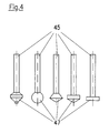
- the thickening 47 for generating the throttle 49 may have different shapes and diameters depending on the application. Some exemplary needles 45 with respective thickenings 47 are shown in FIG Fig. 4 shown.
- a shunt nozzle 51 can also be provided, which allows a portion of the air supplied by the compressed air supply 41 to flow off in front of the housing 25. In this way, the total air flow can be increased and the operating point can be shifted into a favorable range of the supply pressure characteristic.
- a bypass nozzle can also in the devices of Fig. 1 and 2 be used.
- a bipolar measuring needle 45 is shown in more detail.
- Fig. 5 is a photograph shown while in Fig. 6 a simplified cross-sectional view is shown.
- the measuring needle 45 is arranged in a cylindrical receptacle 53 of about 2 to 4 mm in diameter to ensure easy insertion into the actuator 23 and a simple exchange.
- the cylindrical receptacle 53 is followed by a reinforced section 55, which provides increased mechanical stability.
- the turn adjoining tapered portion 57 corresponds to the insertable in a bore 19 to be measured length, so the scanning depth.
- the diameter of the measuring needle 45 shown in the photograph is 0.04 mm.
- the thickening 47 is 0.25 mm long and has a diameter of 0.062 mm. From the end of the reinforced section 55 to the top, the measuring needle 45 is 1.9 mm long. Overall, the measuring needle 45 is therefore thinner than a hair.
- the achievable measuring accuracies are in the range of ⁇ 1 ⁇ m.
- Fig. 7 shows a further embodiment of a device according to the invention, in which an improved seal is provided.
- This embodiment is particularly suitable for applications in which oil residues or chips on the measuring object surface can be expected.
- two concentric O-rings 43, 44 are arranged around the outlet opening 27, which increase the sealing effect.
- means for leak testing are provided.
- a channel 59 connects the compressed air supply 41 with the area between the two O-rings 43, 44.
- a vomvordüse 63 In the compressed air line 61 between the compressed air supply 41 and channel 59 a pronouncevordüse 63, a valve 65 and a first pressure measuring device 67 is integrated.
- the parallel compressed air line 69 which connects the compressed air supply 41 with the interior of the housing 25, a second pressure measuring device 71, a Messvordüse 73 and a third pressure measuring device 75 is integrated.
- a monitoring of the seal can be performed in several ways. For example, before starting a measurement, the valve 65 is placed in connection or passage position, so that the area between the O-rings 43, 44 is supplied with compressed air. Now the pressure is read off at the first pressure measuring device 67 and at the second pressure measuring device 71, respectively. If the sealing by the O-rings 43, 44 is deficient, compressed air escapes from the area between the O-rings 43, 44 and there is a pressure drop across the scholarvordüse 63. This pressure drop can wait for a predetermined pressure build-up time on the difference between the at the first pressure measuring device 67th read pressure and the read at the second pressure measuring device 71 pressure can be determined.
- valve 65 is placed in separation or blocking position, so that the channel 59 is cut off from the supply pressure. A leak can now be detected via a change over time of the pressure read off at the first pressure measuring device 67.
- the continuous measurement of the pressure in the channel 59 makes it possible to continue measuring even if the seal is not perfect, by calculating a suitable correction factor from the determined pressure change and taking it into account in the diameter calculation.
- Fig. 8 shows a side view of a measuring device according to the invention with a housing 25 and a handle 77.
- the diameter B of the housing 25 at the outlet opening 27 is in the illustrated variant 2-3 mm.
- this value can be adapted to the respective measuring conditions. Due to the reliable positioning of the measuring needle 45, it is possible to measure even bores with a diameter of less than 0.1 mm with a hand-held device.
- the principles described above allow a fast and reliable positioning of a probe to be inserted into a bore 19.
- an automatic control in particular based on a closed control loop between the camera 31 and actuator 23
- accidental shocks of the probe can be avoided against the measurement object surface.
- the measurement of very small holes is possible, with a scan operation can be realized in a simple manner.
- the use of the camera 31 has the further advantage that bending of the measuring probe, that is to say the measuring mandrel 11 or the measuring needle 45, can be detected. Even a permanent bending can be determined.
- the measuring probe is positioned after determining the position of the bore 19 via the bore 19 and then lowered. Shortly before reaching the hole opening, the position of the measuring probe is checked by means of the camera 31 or several cameras.
Landscapes
- Physics & Mathematics (AREA)
- General Physics & Mathematics (AREA)
- Measuring Arrangements Characterized By The Use Of Fluids (AREA)
- Length Measuring Devices With Unspecified Measuring Means (AREA)
- A Measuring Device Byusing Mechanical Method (AREA)
- Length Measuring Devices By Optical Means (AREA)
Applications Claiming Priority (1)
| Application Number | Priority Date | Filing Date | Title |
|---|---|---|---|
| DE102007062679.9A DE102007062679B4 (de) | 2007-12-24 | 2007-12-24 | Vorrichtung zur Vermessung von Bohrungen |
Publications (2)
| Publication Number | Publication Date |
|---|---|
| EP2075529A2 true EP2075529A2 (fr) | 2009-07-01 |
| EP2075529A3 EP2075529A3 (fr) | 2015-12-09 |
Family
ID=40428005
Family Applications (1)
| Application Number | Title | Priority Date | Filing Date |
|---|---|---|---|
| EP08022286.2A Withdrawn EP2075529A3 (fr) | 2007-12-24 | 2008-12-22 | Procédé de mesure de forages |
Country Status (2)
| Country | Link |
|---|---|
| EP (1) | EP2075529A3 (fr) |
| DE (1) | DE102007062679B4 (fr) |
Families Citing this family (2)
| Publication number | Priority date | Publication date | Assignee | Title |
|---|---|---|---|---|
| DE102009021471A1 (de) * | 2009-05-15 | 2010-12-09 | Audi Ag | Verfahren zur Herstellung eines Gehäuseteils einer Brennkraftmaschine und Messgerät zur Messung der Dichtigkeit oder Durchgängigkeit von mindestens einem darin angeordneten Kühlmittelkanal |
| DE102010026892A1 (de) | 2010-04-09 | 2011-10-13 | Stotz Feinmesstechnik Gmbh | Vorrichtung zur Vermessung von Objekten |
Family Cites Families (8)
| Publication number | Priority date | Publication date | Assignee | Title |
|---|---|---|---|---|
| GB711865A (en) | 1951-07-26 | 1954-07-14 | Sigma Instr Co Ltd | Improvements in or relating to gauging mandrels for pneumatically operated linear-dimension gauges |
| FR2292952A1 (fr) * | 1974-11-28 | 1976-06-25 | Centre Techn Ind Mecanique | Tete de mesure pour rugosimetre pneumatique |
| JP2929913B2 (ja) | 1993-03-17 | 1999-08-03 | 日産自動車株式会社 | ねじ孔計測装置 |
| JP3494315B2 (ja) | 1994-06-30 | 2004-02-09 | 株式会社東京精密 | 空気マイクロメータ装置 |
| US5653037A (en) | 1994-11-18 | 1997-08-05 | Nissan Motor Co., Ltd. | Apparatus and method for measurement of tapped hole |
| DE19746662A1 (de) * | 1997-06-26 | 1999-02-18 | Fraunhofer Ges Forschung | Meßanordnung zum berührungslosen Erfassen der Innenkontur von Hohlräumen mit einer Lichtquelle |
| AU2003252230A1 (en) | 2002-07-24 | 2004-02-09 | Tokyo Seimitsu Co., Ltd. | Measuring device |
| DE10303250A1 (de) | 2003-01-28 | 2004-08-05 | Delphi Technologies, Inc., Troy | Verfahren zur Vermessung eines Innenraums mittels eines in den Innenraum einströmenden Fluids |
-
2007
- 2007-12-24 DE DE102007062679.9A patent/DE102007062679B4/de not_active Expired - Fee Related
-
2008
- 2008-12-22 EP EP08022286.2A patent/EP2075529A3/fr not_active Withdrawn
Also Published As
| Publication number | Publication date |
|---|---|
| DE102007062679B4 (de) | 2022-08-11 |
| EP2075529A3 (fr) | 2015-12-09 |
| DE102007062679A1 (de) | 2009-06-25 |
Similar Documents
| Publication | Publication Date | Title |
|---|---|---|
| DE19815201A1 (de) | Meßanordnung zur Erfassung von Dimensionen von Prüflingen, vorzugsweise von Hohlkörpern, insbesondere von Bohrungen in Werkstücken, sowie Verfahren zur Messung solcher Dimensionen | |
| DE102007013623A1 (de) | Verfahren und Vorrichtung zum Ausrichten eines Laserstrahls | |
| DE102015102111A1 (de) | Mehrkopf-Laseranlage mit Sensoreinheit | |
| EP1979706B1 (fr) | Dispositif de mesure | |
| EP2999568B1 (fr) | Buse pour une machine de travail au laser et machine correspondante | |
| DE102004043209A1 (de) | Verfahren und Vorrichtung zur Prüfung einer gekrümmten Oberfläche in einem Hohlraum | |
| EP2075529A2 (fr) | Procédé de mesure de forages | |
| WO2018087328A1 (fr) | Dispositif et procédé de détection et/ou d'analyse d'un enlèvement sur une surface d'un élément structural cylindrique | |
| DE10340803A1 (de) | Meßverfahren und Meßanordnung zur Bestimmung der räumlichen Position wenigstens einer Zone der Oberfläche eines Objekts | |
| DE3914014A1 (de) | Verfahren zur bestimmung der ueberlaenge einer optischen faser in einer hohlader | |
| EP1391691B1 (fr) | Procédé de mesure du diamètre d'un trou dans une pièce à usiner. | |
| EP1477274B1 (fr) | Machine-outil | |
| DE102017111819B4 (de) | Bohrungsinspektionsvorrichtung | |
| EP2053351A2 (fr) | Système de mesure, notamment pour la mesure de rainures | |
| EP1960156B1 (fr) | Dispositif et procede de visualisation de positions sur une surface | |
| DE10064847C1 (de) | Verfahren und Vorrichtung zum Vermessen und gegebenenfalls Kalibrieren einer Lochung eines Werkstücks | |
| DE10317488B4 (de) | Technoskop | |
| DE4037934C2 (de) | Verfahren und Vorrichtung zur Messung von Verformungen an Prüfkörpern in Prüfmaschinen | |
| AT520971B1 (de) | Verfahren zur Gütebestimmung | |
| DE10254104B4 (de) | Verfahren und Vorrichtungen zur Bestimmung des Durchmessers eines Loches in einem Werkstück sowie der Orientierung und der Position der Achse des Lochs | |
| DE3641128A1 (de) | Einrichtung zur pneumatischen ermittlung des innendurchmessers eines im querschnitt runden kanales eines prueflings | |
| DE10303250A1 (de) | Verfahren zur Vermessung eines Innenraums mittels eines in den Innenraum einströmenden Fluids | |
| DE19511704A1 (de) | Vorrichtung zur Prüfung der Maßhaltigkeit einer in einem Werkstück befindlichen Ausnehmung | |
| EP2229584A1 (fr) | Sonde et dispositif pour la vérification optique d'objets à mesurer | |
| DE102006031232B4 (de) | Verfahren und Anordnung zum Messen der Verlustleistung eines Laserstrahls einer Laserbearbeitungsmaschine |
Legal Events
| Date | Code | Title | Description |
|---|---|---|---|
| PUAI | Public reference made under article 153(3) epc to a published international application that has entered the european phase |
Free format text: ORIGINAL CODE: 0009012 |
|
| AK | Designated contracting states |
Kind code of ref document: A2 Designated state(s): AT BE BG CH CY CZ DE DK EE ES FI FR GB GR HR HU IE IS IT LI LT LU LV MC MT NL NO PL PT RO SE SI SK TR |
|
| AX | Request for extension of the european patent |
Extension state: AL BA MK RS |
|
| PUAL | Search report despatched |
Free format text: ORIGINAL CODE: 0009013 |
|
| AK | Designated contracting states |
Kind code of ref document: A3 Designated state(s): AT BE BG CH CY CZ DE DK EE ES FI FR GB GR HR HU IE IS IT LI LT LU LV MC MT NL NO PL PT RO SE SI SK TR |
|
| AX | Request for extension of the european patent |
Extension state: AL BA MK RS |
|
| RIC1 | Information provided on ipc code assigned before grant |
Ipc: G01B 13/10 20060101AFI20151104BHEP |
|
| AKY | No designation fees paid | ||
| AXX | Extension fees paid |
Extension state: AL Extension state: MK Extension state: RS Extension state: BA |
|
| REG | Reference to a national code |
Ref country code: DE Ref legal event code: R108 |
|
| STAA | Information on the status of an ep patent application or granted ep patent |
Free format text: STATUS: THE APPLICATION IS DEEMED TO BE WITHDRAWN |
|
| 18D | Application deemed to be withdrawn |
Effective date: 20160610 |