EP2075563A2 - Kapazitive, statische/dynamische Hochtemperatur-Drucksensoren - Google Patents
Kapazitive, statische/dynamische Hochtemperatur-Drucksensoren Download PDFInfo
- Publication number
- EP2075563A2 EP2075563A2 EP08021761A EP08021761A EP2075563A2 EP 2075563 A2 EP2075563 A2 EP 2075563A2 EP 08021761 A EP08021761 A EP 08021761A EP 08021761 A EP08021761 A EP 08021761A EP 2075563 A2 EP2075563 A2 EP 2075563A2
- Authority
- EP
- European Patent Office
- Prior art keywords
- pressure
- diaphragm
- chamber
- sensing
- recited
- Prior art date
- Legal status (The legal status is an assumption and is not a legal conclusion. Google has not performed a legal analysis and makes no representation as to the accuracy of the status listed.)
- Withdrawn
Links
- 230000003068 static effect Effects 0.000 title claims description 14
- 230000008859 change Effects 0.000 claims abstract description 33
- 229910045601 alloy Inorganic materials 0.000 claims abstract description 17
- 239000000956 alloy Substances 0.000 claims abstract description 17
- 230000004044 response Effects 0.000 claims abstract description 6
- 239000000463 material Substances 0.000 claims description 17
- 238000013022 venting Methods 0.000 claims description 16
- 230000003071 parasitic effect Effects 0.000 claims description 15
- 238000004891 communication Methods 0.000 claims description 13
- 238000009530 blood pressure measurement Methods 0.000 claims description 11
- 230000001747 exhibiting effect Effects 0.000 claims description 11
- 239000012212 insulator Substances 0.000 claims description 11
- 230000003647 oxidation Effects 0.000 claims description 11
- 238000007254 oxidation reaction Methods 0.000 claims description 11
- 239000000919 ceramic Substances 0.000 claims description 9
- 239000000523 sample Substances 0.000 abstract description 6
- 229910001026 inconel Inorganic materials 0.000 description 16
- 238000012360 testing method Methods 0.000 description 9
- 238000009423 ventilation Methods 0.000 description 7
- 238000010276 construction Methods 0.000 description 6
- 230000007246 mechanism Effects 0.000 description 5
- 238000000034 method Methods 0.000 description 4
- 230000008901 benefit Effects 0.000 description 3
- 230000000903 blocking effect Effects 0.000 description 3
- 239000000758 substrate Substances 0.000 description 3
- 230000001351 cycling effect Effects 0.000 description 2
- 230000007423 decrease Effects 0.000 description 2
- 238000004519 manufacturing process Methods 0.000 description 2
- 238000005259 measurement Methods 0.000 description 2
- 239000002184 metal Substances 0.000 description 2
- 230000000630 rising effect Effects 0.000 description 2
- 230000035945 sensitivity Effects 0.000 description 2
- 239000010935 stainless steel Substances 0.000 description 2
- 229910001220 stainless steel Inorganic materials 0.000 description 2
- VVQNEPGJFQJSBK-UHFFFAOYSA-N Methyl methacrylate Chemical compound COC(=O)C(C)=C VVQNEPGJFQJSBK-UHFFFAOYSA-N 0.000 description 1
- 229920005372 Plexiglas® Polymers 0.000 description 1
- XUIMIQQOPSSXEZ-UHFFFAOYSA-N Silicon Chemical compound [Si] XUIMIQQOPSSXEZ-UHFFFAOYSA-N 0.000 description 1
- 238000012993 chemical processing Methods 0.000 description 1
- 230000003750 conditioning effect Effects 0.000 description 1
- 239000004020 conductor Substances 0.000 description 1
- 230000007812 deficiency Effects 0.000 description 1
- 239000003989 dielectric material Substances 0.000 description 1
- 230000000694 effects Effects 0.000 description 1
- 238000005516 engineering process Methods 0.000 description 1
- 230000007613 environmental effect Effects 0.000 description 1
- 238000010438 heat treatment Methods 0.000 description 1
- 230000007774 longterm Effects 0.000 description 1
- 230000013011 mating Effects 0.000 description 1
- 238000012986 modification Methods 0.000 description 1
- 230000004048 modification Effects 0.000 description 1
- 238000007789 sealing Methods 0.000 description 1
- 229910052710 silicon Inorganic materials 0.000 description 1
- 239000010703 silicon Substances 0.000 description 1
- 230000002459 sustained effect Effects 0.000 description 1
- 238000012546 transfer Methods 0.000 description 1
Images





Classifications
-
- G—PHYSICS
- G01—MEASURING; TESTING
- G01L—MEASURING FORCE, STRESS, TORQUE, WORK, MECHANICAL POWER, MECHANICAL EFFICIENCY, OR FLUID PRESSURE
- G01L23/00—Devices or apparatus for measuring or indicating or recording rapid changes, such as oscillations, in the pressure of steam, gas, or liquid; Indicators for determining work or energy of steam, internal-combustion, or other fluid-pressure engines from the condition of the working fluid
- G01L23/08—Devices or apparatus for measuring or indicating or recording rapid changes, such as oscillations, in the pressure of steam, gas, or liquid; Indicators for determining work or energy of steam, internal-combustion, or other fluid-pressure engines from the condition of the working fluid operated electrically
- G01L23/12—Devices or apparatus for measuring or indicating or recording rapid changes, such as oscillations, in the pressure of steam, gas, or liquid; Indicators for determining work or energy of steam, internal-combustion, or other fluid-pressure engines from the condition of the working fluid operated electrically by changing capacitance or inductance
- G01L23/125—Devices or apparatus for measuring or indicating or recording rapid changes, such as oscillations, in the pressure of steam, gas, or liquid; Indicators for determining work or energy of steam, internal-combustion, or other fluid-pressure engines from the condition of the working fluid operated electrically by changing capacitance or inductance by changing capacitance
-
- G—PHYSICS
- G01—MEASURING; TESTING
- G01L—MEASURING FORCE, STRESS, TORQUE, WORK, MECHANICAL POWER, MECHANICAL EFFICIENCY, OR FLUID PRESSURE
- G01L9/00—Measuring steady of quasi-steady pressure of fluid or fluent solid material by electric or magnetic pressure-sensitive elements; Transmitting or indicating the displacement of mechanical pressure-sensitive elements, used to measure the steady or quasi-steady pressure of a fluid or fluent solid material, by electric or magnetic means
- G01L9/0041—Transmitting or indicating the displacement of flexible diaphragms
- G01L9/0072—Transmitting or indicating the displacement of flexible diaphragms using variations in capacitance
Definitions
- the subject invention is directed to capacitive pressure sensor, and more particularly, to high temperature capacitive static/dynamic pressure sensors, such as sensors or microphones for detecting acoustic pressure waves in a gas turbine engine, which employs a diaphragm made from a material exhibiting high thermal strength, thermal stability and oxidation resistance at elevated temperatures.
- Capacitive pressure sensors are well known in the art, as disclosed for example in U.S. Patent No. 6,148,674 , the disclosure of which is herein incorporated by reference in its entirety. However, these devices have limited applicability at elevated temperatures. In particular, since the capacitance of prior art pressure sensors are normally in the picoFarad (pF) range, they are susceptible to stray capacitance and other environmental conditions. This makes it difficult to develop high temperature capacitive pressure sensors for use in harsh environment applications, such as, gas turbine applications. Indeed, there are currently no commercially available capacitive pressure sensors capable of operating above 350°C.
- guarding is accomplished by surrounding the sensing electrode area with a non-sensing conductor that is kept at the same voltage as the sensing area itself. This technique is also used to guard a tri-axial cable connecting the pressure detector to a signal conditioning circuit. As a result, there is no loss of the input signal, even though the cable may be as long as up to 10 meters.
- FM frequency modulation
- U.S. Patent No. 7,258,806 to Ho discloses a diaphragm for a capacitive microphone device.
- the diaphragm is made using a first substrate that has a dielectric layer formed thereon. Then a second metallic diaphragm layer is applied to the substrate over the dielectric layer. It is not uncommon to manufacture a diaphragm using layers of materials in order to improve the sensing characteristics of the microphone. However, laminar diaphragms are expensive to manufacture and are not capable of operating in high temperature environments.
- a solution to these deficiencies has been to employ an all metal diaphragm to minimize the thermal mismatch between the diaphragm and the substrate.
- one of the drawbacks of a metal diaphragm in a pressure sensor or microphone is temperature hysteresis and pressure hysteresis at high temperature.
- a useful capacitive pressure sensor having a diaphragm made of Inconel 750 has been manufactured and tested by the present inventors.
- a temperature cycle test from -55°C to 500°C at pressure from 15 psi to 600 psi shows that the temperature hysteresis in such a device is approximately 0.76% and the pressure hysteresis is less approximately 1.3% without any thermal compensation.
- the subject invention is directed to a pressure probe having a diaphragm made of a material that overcomes the drawbacks of the prior art and constructed to provide a more accurate measurement of the pressure (dynamic or static) at high temperatures.
- the subject invention is directed to new and useful capacitive pressure sesnors for high temperature applications, such as for use in a gas turbine engine.
- Certain constructions of the capacitive probes or pressure sensors of the present invention include, inter alia , a sensor housing that defines an interior sensing chamber having a pressure port and an interior reference chamber positioned adjacent to a sensing electrode.
- the reference chamber is separated from the sensing chamber by a deflectable diaphragm made from Haynes 230 alloy, wherein the deflection of the diaphragm in response to an applied pressure in the sensing chamber corresponds to a change in capacitance value detected by the sensing electrode.
- the reference chamber is sealed in a vacuum with a pressure less than 10 mTorr.
- a gap is provided within the reference chamber between the sensing electrode and the diaphragm, and the gap is between about 67 ⁇ m and 100 ⁇ m.
- the sensing electrode is shielded from signal line parasitic capacitance to ground.
- the sensing electrode is shielded from signal line parasitic capacitance to ground by a guard ring.
- the guard ring is driven by a voltage potential equal to a voltage potential running through the signal line.
- a ceramic insulator is disposed between the sensing electrode and guard ring.
- the capacitive pressure sensor of the present invention further includes a mechanism for reading a detected change in capacitance upon deflection of the diaphragm so as to obtain a pressure measurement.
- the pressure sensor further includes a venting conduit that provides communication between the sensing chamber and the reference chamber. It is envisioned that a valve can be associated with the venting conduit for restricting the communication between the sensing chamber and the reference chamber.
- the present invention is also directed to a capacitive dynamic pressure microphone that includes, inter alia , a sensor housing that defines an interior sensing chamber having an open pressure port and an enclosed interior reference chamber accommodating a sensing electrode.
- the microphone further includes a deflectable diaphragm that separates the reference chamber from the sensing chamber and is spaced apart from the sensing electrode by a predetermined gap distance.
- the microphone includes a venting conduit that provides for communication between the sensing chamber and the reference chamber for maintaining a balanced static background pressure therebetween.
- the venting conduit is configured so that a change in pressure in the sensing chamber leads ahead of a corresponding change in pressure in the reference chamber by a predetermined time period.
- a pressure differential between the sensing chamber and the reference chamber over the time period causes a corresponding change in the deflection of the diaphragm over the same time period, causing a corresponding change in the gap distance over the time period, resulting in a corresponding change in the capacitance value detected by the sensing electrode over said time period.
- the deflectable diaphragm is constructed from a material that exhibits a high thermal strength, a thermal stability and oxidation resistance at temperatures in excess of about 750°C.
- the deflectable diaphragm is constructed from a material that exhibits a high thermal strength and a thermal stability at temperatures up to about 1150°C.
- the deflectable diaphragm is constructed from Haynes 230 alloy.
- a gap is provided within the reference chamber between the sensing electrode and the diaphragm.
- the gap can range between about 20 ⁇ m and about 200 ⁇ m, and is preferably between about 67 ⁇ m and 100 ⁇ m.
- the sensing electrode is shielded from signal line parasitic capacitance to ground.
- the sensing electrode is shielded from signal line parasitic capacitance to ground by a guard ring.
- the guard ring is driven by a voltage potential equal to a voltage potential running through the signal line.
- a ceramic insulator is disposed between the sensing electrode and guard ring.
- the capacitive pressure microphone of the present invention further includes a mechanism for reading a detected change in capacitance upon deflection of the diaphragm so as to obtain a pressure measurement.
- the microphone further includes a valve associated with the venting conduit for restricting the communication between the sensing chamber and the reference chamber.
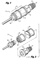
- Fig. 1 is a perspective view of a capacitive pressure sensor constructed in accordance with a preferred embodiment of the subject invention
- Fig. 2 is a perspective view of the capacitive pressure sensor of Fig. 1 with parts separated for ease of illustration;
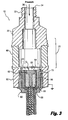
- Fig. 3 is a cross sectional view of the capacitive pressure sensor of Figs. 1 and 2 ;
- Fig. 4 is a cross sectional view of a capacitive microphone constructed in accordance with a preferred embodiment of the present invention.
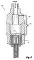
- Fig. 5 is a cross sectional view of a further embodiment of the capacitive microphone of the present invention wherein the microphone includes a valve associated with the venting tube that extends between the pressure reference chamber and the pressure port;
- Fig. 6 is a cross sectional view of a further embodiment of the capacitive microphone of the present invention wherein the microphone includes a ventilation passage that extends between the pressure reference chamber and the pressure port;
- Fig. 7 is a schematic of a capacitive remote readout system based on MC900 modular electronics for both dynamic and static pressure measurement;
- Fig. 8 is a schematic of a capacitive remote readout system based on a AD7747 capacitance-to-digital converter chip for static pressure measurement;
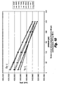
- Fig. 9 is a graph showing sensor output versus pressure (15 psi to 600 psi) and temperature (-55°C to 500°C) for a preferred embodiment of the subject invention.
- Fig. 10 is a graph showing sensor output versus pressure (15 psi to 250 psi) and temperature (19°C to 750°C) for a preferred embodiment of the subject invention
- Fig. 11 is a graph showing sensor output versus acoustic pressure intensity (0.125 psi pk-to-pk to 1.5 psi pk-to-pk at 23 °C);
- Fig. 12 is a graph showing sensor output versus acoustic pressure intensity (0.125 psi pk-to-pk to 1.5 psi pk-to-pk at 500°C);
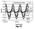
- Fig. 13 is a graph showing sensor output versus acoustic pressure intensity (0.125 psi pk-to-pk to 1.5 psi pk-to-pk at 700 °C).
- a capacitive probe or pressure sensor constructed in accordance with a preferred embodiment of the subject invention and designated generally by reference numeral 10.
- Pressure sensor 10 is adapted and configured for high temperature applications, such as for use in a gas turbine engine.
- pressure sensor 10 includes a housing assembly 20 having a mounting section 30, a diaphragm section 40, and electrode support section 50.
- the electrode support section is adapted and configured for receiving an electrode assembly 60.
- the mounting section 30 of the housing assembly 20 includes a series of threads 32 associated with one end 34 thereof.
- the threads 32 can be used to connect the sensor 10 to the pressure source to be measured.
- the threads 32 can be used to connect that sensor 10 to the housing of a combustor.
- the mounting section 30 defines a pressure port 36 that extends over its entire length.
- the pressure port 36 of the mounting section 30 terminates in a sensing chamber 42 formed in the diaphragm section 40.
- the diaphragm section 40 includes a flexible diaphragm 44 positioned adjacent to the sensing chamber 42. The diaphragm 44 will be discussed in more detail hereibelow.
- Electrode assembly 60 when the electrode assembly 60 is inserted into the electrode support section 50, a reference chamber 52 is formed between end 64 of the electrode 62 and the diaphragm 44. Electrode assembly 60 has a series of threads 63 formed on its outer periphery which are adapted and configured for mating with a series of threads 54 formed on an inner diameter of the electrode support section 50 of housing 20. One the electrode assembly is threaded into the electrode support section the two parts can be welded together as shown in order to improve the sealing of the reference chamber 52.
- the three component parts of the housing assembly 20 are made of the same alloy and are welded together into a unitary structure.
- the unit has a very good hermetic seal and the pressure leak rate is less than 10 -10 atm cc/sec at room temperature.
- any number of parts can be used to make up the sensor's housing assembly 20 without departing for the spirit and scope of the present invention.
- Fig. 3 illustrates that the diaphragm section 40 of the housing assembly 20 is made from a single part, it is envisioned that the flexible diaphragm 44 can be formed as a separate piece that is later welded onto a cylindrical main body portion.
- Fig. 3 which illustrates that the reference chamber 52 is sealed and separated from the sensing chamber 42 by the deflectable diaphragm 44.
- the reference chamber 52 is sealed in a vacuum with a pressure less than 10 mTorr.
- the diaphragm 44 is constructed from a material exhibiting high thermal strength, thermal stability and oxidation resistance at elevated temperatures.
- the deflection of the diaphragm 44 in response to an applied pressure in the sensing chamber 42 corresponds to a capacitance value detected by the sensing electrode 62.
- a system is provided for remotely reading a detected change in capacitance upon deflection of the diaphragm 44, so as to obtain a pressure measurement, as shown for example in Figs. 7 and 8 (discussed hereinbelow).
- the deflectable diaphragm 44 is constructed from a material exhibiting high thermal strength, thermal stability and oxidation resistance at temperatures in excess of about 750°C.
- the deflectable diaphragm is constructed from a material exhibiting high thermal strength, thermal stability and oxidation resistance at temperatures up to about 1000°C.
- the deflectable diaphragm is constructed from Haynes 230 alloy.
- the thickness of the diaphragm is about 0.018". This thickness is preferred for a static pressure sensor with an input range of about 600 psi. The thickness of the diaphragm is varied depending of the pressure range for the sensor. For example, for sensor having a pressure input of 10 psi, a diaphragm having a thickness of about 0.003" could be used.
- a gap "G" is provided within the reference chamber 52 between the sensing electrode 62 and the diaphragm 44.
- the gap is between about 67 ⁇ m and 100 ⁇ m.
- the gap distance corresponds to a certain range of capacitance values, for example, 0.93 pF to 0.63 pF.
- the sensing electrode 62 is shielded from signal line parasitic capacitance to ground.
- the sensing electrode 62 is shielded from signal line parasitic capacitance to ground by a guard ring 66.
- the guard ring 66 is driven by a voltage potential equal to a voltage potential running through the signal line.
- an inverter buffer circuit can be used.
- a ceramic insulator 68 is disposed between the sensing electrode 62 and guard ring 66.
- Another ceramic insulator 69 surrounds the guard ring 66 and a stainless steel shield 72 surrounds insulator 69.
- Haynes alloy 230 has excellent high temperature strength, oxidation resistance and long-term thermal stability. For these reasons it is often used in aerospace, chemical processing and high temperature heating applications.
- the thermal properties of Haynes alloy 230 can be readily compared to the thermal properties of Inconel 750, which is commonly used as a material for mechanical diaphragms in industrial applications, to show its advantages.
- a comparison of modulus of elasticity and thermal expansion coefficient versus temperature for both Haynes 230 and Inconel 750 is summarized in Table 1.0 and Table 2.0.
- the value of the modulus of elasticity of Inconel 750 drops approximately 40% when it heats up from 26.7°C to 816°C, while the modulus of elasticity of Haynes 230 alloy drops approximately 29% when it heats up from 26.7°C to 1000°C.
- the difference of thermal expansion coefficient for Inconel 750 between a temperature range of 26.7°C to 93°C and a temperature range of 26.7°C to 871°C is about 25.3%.
- the difference of thermal expansion coefficient is about 21.1% between a temperature range of 25°C to 100°C and a temperature range of 25°C to 1000°C.
- Haynes 230 alloy exhibits better thermal strength and thermal stability than Inconel 750.
- Table 1.0 Comparison of Dynamic Modulus of Elasticity Between Inconel 750 and Haynes 230 Inconel 750 Haynes 230 Temperature (°C) Modulus (GPa) Temperature (°C) Modulus (GPa) 26.7 213.7 25 211 260 197.9 100 207 538 172.4 200 202 732 144.8 300 196 816 127.6 400 190 500 184 600 177 700 171 800 164 900 157 1000 150
- Table 2.0 Comparison of Thermal Expansion Coefficient Between Inconel 750 and Haynes 230 Inconel 750 Haynes 230 Temperature Range (°C) Thermal expansion coefficient (10 -6 m/m-°C) Temperature range (°C) Thermal expansion coefficient (10 -6 m/m-°C) 26.7 to 93 12.1 25 to 100 12.7 26.7 to 360 13.5 25 to 200 13.0 26.7 to 538 14.2 25 to 300 13.3 26.7 to 649
- a capacitive pressure sensor based on Haynes 230 alloy is not only highly resistant to extreme temperature, but it also retains high accuracy and high stability at temperatures up to about 800°C.
- a relatively small capacitance variation can be precisely measured and transmitted to a remote readout electronic circuit through, for example, a 3 meter long tri-axial cable.
- a guard ring 66 is driven by the same voltage potential as that which is running through the signal line. Therefore, there is no AC current between the signal line and the guard ring 66, and any capacitance between the two does not affect the charge transfer through the signal line. This means that the capacitance between the guard ring 66 and the signal line does not have any contribution to the output.
- FIG. 7 there is shown a schematic of a capacitive remote readout system 40 based upon MC900 modular electronics made by the French company Fogale nanotech.
- the thermal drift for the system is 0.002% per °C and the bandwidth is about 10 kHz.
- the readout system 40 is suitable for both dynamic and static pressure measurement.
- FIG. 8 there is shown a schematic of another capacitive readout system 50, which is based on a capacitance-to-digital converter ASIC chip, referred to as AD7747, which is made by Analog Devices.
- the resolution of the AD7747 chip is down to 20 aF (10 -18 F) and it has an accuracy in the range of 4 ⁇ 10 fF (10 -15 F).
- Full-scale (changing) capacitance range is ⁇ 8 pF.
- the update rate of the chip is 5 Hz to 45 Hz. However, it is only suitable for static and low frequency pressure measurement.
- the capacitive pressure sensor of the subject invention has been fully characterized over temperature cycle tests.
- the temperature profile for the test was as follows, wherein the time period for each temperature point extended for about 45 minutes: 25°C ⁇ 200°C ⁇ 350°C ⁇ 500°C ⁇ 350°C ⁇ 200°C ⁇ 25°C ⁇ -55°C ⁇ 25°C.
- FIG. 9 A typical sensor output versus pressure (15 psi to 600 psi) and temperature (-55°C to 500°C) is shown graphically in Fig. 9 .
- the output is relatively linear over the entire temperature and pressure range.
- the temperature hysteresis is about 0.367% F.S. (full scale) and pressure hysteresis is about 0.46% F.S. (full scale).
- the performance data over -55°C to 500°C is summarized below in Table 3.0.
- Table 3.0 Sensor Performance Summary First Prototype High Temperature Capacitive Pressure Sensor Based on Haynes 230 Diaphragm.
- Unit Performance Summary Parameter Value (min) Value (max) Units Vnull @ Cold (-55°C) 4868.541 mV @ Hot (500°C) 5168.346 mV @ Room (25°C) 4917.708 mV Span 15 600 psi @ Cold (-55°C) -1309.189 mV @ Hot (500°C) -1523.344 mV @ Room -1333.840 mV Temperature range -55 500 °C Straight-Line Best Fit Error - Vfs -1.324% 1.699% %Span Straight-Line Best Fit Error - Vnull -0.959% 0.961% %Span Vout, Pressure Hysteresis -0.460% 0.035% %Span Vout, Temperature Hysteresis 0.367% %Span Vout, Zero Repeatability -0.474% 0.009% %Span RSS 0.756% %Span Hot Temperature Repeatability 0.26% 0.48% %Span
- the maximum temperature of current temperature cycling ovens is about 500°C
- a different furnace was used if temperature was to be above 500°C.
- the Haynes 230 based capacitive pressure sensor of the subject invention was tested in a higher temperature but less controllable furnace. Therefore, the performance data from 500°C to 750°C is coarsely characterized based on a manual data recording procedure.
- the temperature profile in this furnace was as follows, wherein the time period for each temperature point extended for about 45 minutes: 500°C ⁇ 600°C ⁇ 700°C ⁇ 750°C ⁇ 700°C ⁇ 600°C ⁇ 500°C ⁇ Room-temp ⁇ 19 °C.
- Fig. 10 The result of sensor output versus pressure (15 psi to 250 psi) and temperature (19°C to 750°C) is shown graphically in Fig. 10 .
- the output of the sensor is still linear. However, there is relatively larger hysteresis.
- the temperature hysteresis is about 1.25 % F.S. (full scale) and pressure hysteresis is about 2.1% F.S. (full scale).
- the sensor was still functional after 48 hours of continuous testing at 750°C.
- a capacitive pressure sensor made of Haynes 230 alloy has been built and fully characterized in two different furnaces over temperature range from -55°C to 500°C and from 21°C to 750°C.
- the capacitance change over pressure has been measured with a remote readout system through a three-meter long tri-axial cable.
- the accuracy is better than 0.5% over a temperature range of -55°C to 500°C and about 2.1% over a temperature range of 20°C to 750°C without any temperature compensation.
- the sensor was still functional after 48 hours of testing at 750°C. It is thus suitable for gas turbine engine control applications.
- Microphone 100 is adapted and configured for high temperature applications, such as for use in a gas turbine engine.
- microphone 100 includes a housing assembly 120 having a mounting section 130, a diaphragm section 140, and electrode support section 150.
- the electrode support section 150 is adapted and configured for receiving an electrode assembly 160.
- the mounting section 130 of the housing assembly 120 includes a series of threads 132 associated with end 134.
- the threads 132 can be used to connect the microphone 100 to the pressure source to be measured.
- the threads 132 can be used to connect that microphone 100 to the housing of a combustor.
- the mounting section 130 defines a pressure port 136 that extends over its entire length.
- the pressure port 136 of the mounting section 130 terminates in a sensing chamber 142 formed in the diaphragm section 140.
- the diaphragm section 140 includes a flexible diaphragm 144 positioned adjacent to the sensing chamber 142. The diaphragm 144 will be discussed in more detail hereibelow.
- a reference chamber 152 is formed between end 164 of the electrode 162 and the diaphragm 144.
- the component parts of the housing assembly 120 are made of the same alloy and are welded together into a unitary structure.
- the unit has a very good hermetic seal and the pressure leak rate is less than 10 -10 atm cc /sec at room temperature.
- any number of parts can be used to make up the sensor's housing assembly 120 without departing for the spirit and scope of the present invention.
- the diaphragm 144 is constructed from a material exhibiting high thermal strength, thermal stability and oxidation resistance at elevated temperatures.
- the deflection of the diaphragm 144 in response to an applied pressure in the sensing chamber 142 corresponds to a capacitance value detected by the sensing electrode 162.
- a system is provided for remotely reading a detected change in capacitance upon deflection of the diaphragm 144, so as to obtain a pressure measurement, as shown for example in Figs. 7 and 8 (discussed supra).
- the deflectable diaphragm 144 is constructed from a material exhibiting high thermal strength, thermal stability and oxidation resistance at temperatures in excess of about 750°C.
- the deflectable diaphragm is constructed from a material exhibiting high thermal strength, thermal stability and oxidation resistance at temperatures up to about 1000°C. More preferably, the deflectable diaphragm is constructed from Haynes 230 alloy. In certain constructions, the diaphragm is about between 80 ⁇ m to 100 ⁇ m think.
- a gap "G" is provided within the reference chamber 152 between the sensing electrode 162 and the diaphragm 144.
- the gap is between about 67 ⁇ m and 100 ⁇ m.
- the gap distance corresponds to a certain range of capacitance values, for example, 0.93 pF to 0.63 pF.
- the sensing electrode 162 is shielded from signal line parasitic capacitance to ground.
- the sensing electrode 162 is shielded from signal line parasitic capacitance to ground by a guard ring 166.
- the guard ring 166 is driven by a voltage potential equal to a voltage potential running through the signal line.
- an inverter buffer circuit can be used.
- a ceramic insulator 168 is disposed between the sensing electrode 162 and guard ring 166.
- Another ceramic insulator 169 surrounds the guard ring 166 and a stainless steel shield 172 surrounds insulator 169.
- microphone 100 includes a ventilation tube 180 extending between the sensing chamber 142 and the reference chamber 152.
- the tube 180 maintains the pressure balance on both sides of the diaphragm 144.
- the diaphragm 144 will still respond to a dynamic pressure change since the thin tube 180 will add a delay of acoustic signal to the other side of the diaphragm 144.
- the tube 180 will enable the microphone to respond to an acoustic signal over a high background pressure up to 800 psi.
- the diaphragm is between about 80 - 100 ⁇ m thick with a diameter of about 0.4 inch.
- the gap between the bottom electrode and the diaphragm is between about 67 ⁇ m and 100 ⁇ m which corresponds to a capacitance value of 0.93 pF to 0.63 pF.
- Fig. 5 illustrates a further embodiment of the inventive microphone designated by reference numeral 200.
- Microphone 200 is similar in structure to microphone 100, with the exception that the vent tube 280 includes a valve mechanism 290. By blocking the vent tube 280 using the valve mechanism 290, the reference chamber 252 will be sealed with a reference pressure. It becomes an absolute pressure sensor as shown in Fig. 3 . Using the devices described above, a small capacitance variation can be precisely measured and transmitted to a remote readout electronic circuit though a 3 meter long cable.
- Capacitive microphone 100 of the present invention was tested using an acoustic generator that includes a 4" mini-subwoofer mounted on a plexiglass plate.
- a 1 ⁇ 2" pipe was used as a resonator.
- the resonator covered the frequency range from 170 Hz to 640 Hz.
- the pressure wave intensity increased in an approximately logarithmic fashion, with both frequency examples needing less than 5% of maximum system power to produce ⁇ 1 psi waves.
- Outputs as high as ⁇ 2.0 psi were sustained at rather low power input levels, with the power requirement rising as wave frequency rises (due to drop-off of driver efficiency with rising frequency).
- the output pressure was first calibrated with a PCB sensor mounted on the resonator.
- the capacitive microphone was then mounted on the same location and the output was normalized against the PCB data.
- the capacitive readout system was based on a remote readout system MC900 modular electronics by Fogale nanotech. The thermal drift was 0.002% per degree Celsius and the bandwidth was 10kHz. Noise is about 0.5x10⁻⁶ pF RMS/sqrt(Hz).
- the microphone was then calibrated using a highly accurate Mensor system which is usually used to calibrate a static pressure sensor. The microphone's accuracy was then determined through a series of temperature cycling tests.
- microphone 300 includes a housing assembly 320 having a mounting section 330, a diaphragm section 340, and electrode support section 350.
- the electrode support section 350 is adapted and configured for receiving an electrode assembly 360.
- microphone 300 includes a ventilation port 380 formed within the housing assembly 320 of the microphone which extends between the sensing chamber 342 and the reference chamber 352.
- the ventilation port 380 maintains the pressure balance on both sides of the diaphragm 344.
- the ventilation port 380 can be formed in three sections as shown in Fig. 6 . Radialy passages 332/352 are drilled into the mounting section 330 and the electrode support section 350, respectively, of the housing assembly 320. An axial passage 346 is drilled into the diaphragm section 340 which aligns with axial passages 334/354 formed in each of the mounting and electrode support sections. Blocking covers 370 can be used to seal off the ventilation port 380 from the exterior of the microphone 300.
- a valve can be associated with the ventilation port 380 for restricting or eliminating the flow between the sensing chamber and the reference chamber.
- Typical sensor outputs versus different pressure wave intensities and temperatures are shown in Figs. 11 through 13 .
- the acoustic output frequency was fixed at 318 Hz
- the acoustic pressure intensity was varied from 0.125 psi (pk-to-pk) to 1.5 psi (pk-to-pk)
- temperature was changed from 23 °C ⁇ 500 °C ⁇ 700°C.
- the sensitivity of the microphone at different temperatures is listed in Table 5.0.
- there was a DC bias shifting over the temperature range The bias changed from 8.63 V at 23 °C to 8.72 V at 700 °C. Such a bias shifting can be reduced by running the sensor through multiple temperature cycles.
- the resolution was less than 0.035 psi.
- the sensor was able to respond to acoustic pressure at 750 °C. By adjusting the gap thickness between the two electrode plates, the microphone works up to 800 °C.
- a capacitive microphone constructed in accordance with the present invention is suitable for a temperature range of 23 °C to 800 °C.
- the microphone is stable over a wide temperature range and the resolution is less than 0.035 psi.
- the bandwidth of the microphone system is greater than 1000 Hz.
Landscapes
- Physics & Mathematics (AREA)
- General Physics & Mathematics (AREA)
- Chemical & Material Sciences (AREA)
- Engineering & Computer Science (AREA)
- Combustion & Propulsion (AREA)
- Measuring Fluid Pressure (AREA)
Applications Claiming Priority (2)
| Application Number | Priority Date | Filing Date | Title |
|---|---|---|---|
| US971507P | 2007-12-31 | 2007-12-31 | |
| US12/215,735 US7765875B2 (en) | 2007-12-31 | 2008-06-30 | High temperature capacitive static/dynamic pressure sensors |
Publications (2)
| Publication Number | Publication Date |
|---|---|
| EP2075563A2 true EP2075563A2 (de) | 2009-07-01 |
| EP2075563A3 EP2075563A3 (de) | 2011-10-19 |
Family
ID=42358274
Family Applications (1)
| Application Number | Title | Priority Date | Filing Date |
|---|---|---|---|
| EP08021761A Withdrawn EP2075563A3 (de) | 2007-12-31 | 2008-12-15 | Kapazitive, statische/dynamische Hochtemperatur-Drucksensoren |
Country Status (2)
| Country | Link |
|---|---|
| EP (1) | EP2075563A3 (de) |
| JP (1) | JP2009162751A (de) |
Cited By (7)
| Publication number | Priority date | Publication date | Assignee | Title |
|---|---|---|---|---|
| WO2011015797A1 (fr) | 2009-08-07 | 2011-02-10 | Nanotec Solution | Capteur de pression capacitif integrant une mesure de temperature compatible avec les milieux chauds |
| US8943895B2 (en) | 2012-09-07 | 2015-02-03 | Dynisco Instruments Llc | Capacitive pressure sensor |
| US8984952B2 (en) | 2012-09-07 | 2015-03-24 | Dynisco Instruments Llc | Capacitive pressure sensor |
| US9103738B2 (en) | 2012-09-07 | 2015-08-11 | Dynisco Instruments Llc | Capacitive pressure sensor with intrinsic temperature compensation |
| AT515945A4 (de) * | 2014-09-05 | 2016-01-15 | Piezocryst Advanced Sensorics | Sensorelement |
| CN107617742A (zh) * | 2016-07-13 | 2018-01-23 | 安萨尔多能源英国知识产权有限公司 | 用于制造机械部件的方法 |
| CN116929415A (zh) * | 2022-04-11 | 2023-10-24 | 午芯(辽宁省)高科技有限公司 | 悬浮式电容敏感芯片 |
Families Citing this family (4)
| Publication number | Priority date | Publication date | Assignee | Title |
|---|---|---|---|---|
| US8704538B2 (en) * | 2010-07-01 | 2014-04-22 | Mks Instruments, Inc. | Capacitance sensors |
| JP5963486B2 (ja) * | 2012-03-15 | 2016-08-03 | 日本電産コパル電子株式会社 | 静電容量センサ、測定装置、および測定方法 |
| US10139313B2 (en) * | 2015-07-22 | 2018-11-27 | Teknologian Tutkimuskeskus Vtt Oy | Capacitive cylinder pressure sensor |
| KR102626734B1 (ko) * | 2021-12-28 | 2024-01-17 | 엘에스일렉트릭(주) | 가스 차단기용 센서 지그 |
Citations (2)
| Publication number | Priority date | Publication date | Assignee | Title |
|---|---|---|---|---|
| US6148674A (en) | 1999-09-15 | 2000-11-21 | Park; Kyong M. | Shielded capacitive pressure sensor |
| US7258806B1 (en) | 2006-04-10 | 2007-08-21 | Touch Micro-System Technology Inc. | Method of fabricating a diaphragm of a capacitive microphone device |
Family Cites Families (9)
| Publication number | Priority date | Publication date | Assignee | Title |
|---|---|---|---|---|
| US3352157A (en) * | 1965-06-17 | 1967-11-14 | Henry L B Seegmiller | Inertia diaphragm pressure transducer |
| US3619742A (en) * | 1970-05-21 | 1971-11-09 | Rosemount Eng Co Ltd | Shielded capacitance pressure sensor |
| US3948102A (en) * | 1974-07-31 | 1976-04-06 | The United States Of America As Represented By The Administrator Of The National Aeronautics And Space Administration | Trielectrode capacitive pressure transducer |
| JPS59148842A (ja) * | 1983-02-15 | 1984-08-25 | Matsushita Electric Ind Co Ltd | 静電容量形圧力センサの製造方法 |
| JPH05296865A (ja) * | 1992-04-20 | 1993-11-12 | Sumitomo Electric Ind Ltd | 圧力検出器 |
| FR2705781B1 (fr) * | 1993-05-25 | 1995-08-25 | Schlumberger Services Petrol | Capteur de pression à membrane comportant un système de protection anti-choc, et gradiomanomètre incorporant un tel capteur. |
| US7107853B2 (en) * | 2004-04-23 | 2006-09-19 | Kulite Semiconductor Products, Inc. | Pressure transducer for measuring low dynamic pressures in the presence of high static pressures |
| JP2005351744A (ja) * | 2004-06-10 | 2005-12-22 | Nabtesco Corp | 静電容量型圧力センサ |
| DE102006010804A1 (de) * | 2006-03-07 | 2007-09-20 | Eads Deutschland Gmbh | Hochtemperatur-Drucksensorelement, insbesondere zur Messung von Drücken innerhalb von Triebwerken, Verfahren zu dessen Herstellung und Bauteil für Triebwerke |
-
2008
- 2008-12-15 EP EP08021761A patent/EP2075563A3/de not_active Withdrawn
- 2008-12-24 JP JP2008326837A patent/JP2009162751A/ja active Pending
Patent Citations (2)
| Publication number | Priority date | Publication date | Assignee | Title |
|---|---|---|---|---|
| US6148674A (en) | 1999-09-15 | 2000-11-21 | Park; Kyong M. | Shielded capacitive pressure sensor |
| US7258806B1 (en) | 2006-04-10 | 2007-08-21 | Touch Micro-System Technology Inc. | Method of fabricating a diaphragm of a capacitive microphone device |
Cited By (10)
| Publication number | Priority date | Publication date | Assignee | Title |
|---|---|---|---|---|
| WO2011015797A1 (fr) | 2009-08-07 | 2011-02-10 | Nanotec Solution | Capteur de pression capacitif integrant une mesure de temperature compatible avec les milieux chauds |
| US8770033B2 (en) | 2009-08-07 | 2014-07-08 | Nanotec Solution | Capactive pressure sensor incorporating a temperature measurement and compatible with hot environments |
| US8943895B2 (en) | 2012-09-07 | 2015-02-03 | Dynisco Instruments Llc | Capacitive pressure sensor |
| US8984952B2 (en) | 2012-09-07 | 2015-03-24 | Dynisco Instruments Llc | Capacitive pressure sensor |
| US9103738B2 (en) | 2012-09-07 | 2015-08-11 | Dynisco Instruments Llc | Capacitive pressure sensor with intrinsic temperature compensation |
| AT515945A4 (de) * | 2014-09-05 | 2016-01-15 | Piezocryst Advanced Sensorics | Sensorelement |
| AT515945B1 (de) * | 2014-09-05 | 2016-01-15 | Piezocryst Advanced Sensorics | Sensorelement |
| CN107617742A (zh) * | 2016-07-13 | 2018-01-23 | 安萨尔多能源英国知识产权有限公司 | 用于制造机械部件的方法 |
| CN107617742B (zh) * | 2016-07-13 | 2022-03-11 | 安萨尔多能源英国知识产权有限公司 | 用于制造机械部件的方法 |
| CN116929415A (zh) * | 2022-04-11 | 2023-10-24 | 午芯(辽宁省)高科技有限公司 | 悬浮式电容敏感芯片 |
Also Published As
| Publication number | Publication date |
|---|---|
| JP2009162751A (ja) | 2009-07-23 |
| EP2075563A3 (de) | 2011-10-19 |
Similar Documents
| Publication | Publication Date | Title |
|---|---|---|
| US7765875B2 (en) | High temperature capacitive static/dynamic pressure sensors | |
| EP2075563A2 (de) | Kapazitive, statische/dynamische Hochtemperatur-Drucksensoren | |
| US8770033B2 (en) | Capactive pressure sensor incorporating a temperature measurement and compatible with hot environments | |
| US8141429B2 (en) | High temperature capacitive static/dynamic pressure sensors and methods of making the same | |
| US6295875B1 (en) | Process pressure measurement devices with improved error compensation | |
| US7841239B2 (en) | Electrostatic capacitance diaphragm vacuum gauge and vacuum processing apparatus | |
| US4924701A (en) | Pressure measurement system | |
| US5396803A (en) | Dual balanced capacitance manometers for suppressing vibration effects | |
| US7819014B1 (en) | Capacitive gage pressure sensor with vacuum dielectric | |
| US8943895B2 (en) | Capacitive pressure sensor | |
| US9103738B2 (en) | Capacitive pressure sensor with intrinsic temperature compensation | |
| US8984952B2 (en) | Capacitive pressure sensor | |
| JP2007147616A (ja) | 流体の圧力および温度を測定するセンサ装置 | |
| JP2004518953A (ja) | 圧力センサおよびそれが組み込まれたロケットエンジン | |
| JP3325879B2 (ja) | 相対圧センサ | |
| JPS63217242A (ja) | 圧力測定変換器 | |
| RU2603446C1 (ru) | Устройство для измерения давления и температуры | |
| US6499352B2 (en) | Pressure measuring cell | |
| JP3652346B2 (ja) | フローセンサ | |
| US12372418B2 (en) | Method of shielding capacitive pressure sensor | |
| US12313488B2 (en) | Thermal insulation system for a capacitance diaphragm gauge | |
| CN118443096A (zh) | 一种气体流量光纤光栅传感器及其制作方法 | |
| Talbot et al. | Dielectric-insensitive capacitive differential pressure gauge for use at low temperature | |
| HK1195613B (en) | Capacitive pressure sensor | |
| HK1195808B (en) | Capacitive pressure sensor |
Legal Events
| Date | Code | Title | Description |
|---|---|---|---|
| PUAI | Public reference made under article 153(3) epc to a published international application that has entered the european phase |
Free format text: ORIGINAL CODE: 0009012 |
|
| AK | Designated contracting states |
Kind code of ref document: A2 Designated state(s): AT BE BG CH CY CZ DE DK EE ES FI FR GB GR HR HU IE IS IT LI LT LU LV MC MT NL NO PL PT RO SE SI SK TR |
|
| AX | Request for extension of the european patent |
Extension state: AL BA MK RS |
|
| PUAL | Search report despatched |
Free format text: ORIGINAL CODE: 0009013 |
|
| AK | Designated contracting states |
Kind code of ref document: A3 Designated state(s): AT BE BG CH CY CZ DE DK EE ES FI FR GB GR HR HU IE IS IT LI LT LU LV MC MT NL NO PL PT RO SE SI SK TR |
|
| AX | Request for extension of the european patent |
Extension state: AL BA MK RS |
|
| RIC1 | Information provided on ipc code assigned before grant |
Ipc: G01L 9/00 20060101ALI20110914BHEP Ipc: G01L 23/12 20060101ALI20110914BHEP Ipc: G01L 9/12 20060101AFI20110914BHEP |
|
| 17P | Request for examination filed |
Effective date: 20120418 |
|
| AKX | Designation fees paid |
Designated state(s): AT BE BG CH CY CZ DE DK EE ES FI FR GB GR HR HU IE IS IT LI LT LU LV MC MT NL NO PL PT RO SE SI SK TR |
|
| STAA | Information on the status of an ep patent application or granted ep patent |
Free format text: STATUS: THE APPLICATION IS DEEMED TO BE WITHDRAWN |
|
| 18D | Application deemed to be withdrawn |
Effective date: 20120420 |