EP2075666B1 - Système et procédé pour établir et contrôler dynamiquement la consommation d'énergie dans des centres de données à grande échelle ou infrastructure IT - Google Patents
Système et procédé pour établir et contrôler dynamiquement la consommation d'énergie dans des centres de données à grande échelle ou infrastructure IT Download PDFInfo
- Publication number
- EP2075666B1 EP2075666B1 EP08254170.7A EP08254170A EP2075666B1 EP 2075666 B1 EP2075666 B1 EP 2075666B1 EP 08254170 A EP08254170 A EP 08254170A EP 2075666 B1 EP2075666 B1 EP 2075666B1
- Authority
- EP
- European Patent Office
- Prior art keywords
- power
- clusters
- states
- energy
- managed
- Prior art date
- Legal status (The legal status is an assumption and is not a legal conclusion. Google has not performed a legal analysis and makes no representation as to the accuracy of the status listed.)
- Not-in-force
Links
Images




Classifications
-
- H—ELECTRICITY
- H02—GENERATION; CONVERSION OR DISTRIBUTION OF ELECTRIC POWER
- H02J—ELECTRIC POWER NETWORKS; CIRCUIT ARRANGEMENTS OR SYSTEMS FOR SUPPLYING OR DISTRIBUTING ELECTRIC POWER; SYSTEMS FOR STORING ELECTRIC ENERGY
- H02J1/00—Circuit arrangements for DC mains or DC distribution networks
- H02J1/14—Balancing load and power generation in DC networks
-
- G—PHYSICS
- G06—COMPUTING OR CALCULATING; COUNTING
- G06F—ELECTRIC DIGITAL DATA PROCESSING
- G06F1/00—Details not covered by groups G06F3/00 - G06F13/00 and G06F21/00
- G06F1/26—Power supply means, e.g. regulation thereof
- G06F1/266—Arrangements to supply power to external peripherals either directly from the computer or under computer control, e.g. supply of power through the communication port, computer controlled power-strips
-
- G—PHYSICS
- G06—COMPUTING OR CALCULATING; COUNTING
- G06F—ELECTRIC DIGITAL DATA PROCESSING
- G06F1/00—Details not covered by groups G06F3/00 - G06F13/00 and G06F21/00
- G06F1/26—Power supply means, e.g. regulation thereof
- G06F1/32—Means for saving power
- G06F1/3203—Power management, i.e. event-based initiation of a power-saving mode
Definitions
- the present invention is generally related to energy consumption More particularly, the present invention is related to a system and method to establish and dynamically control energy consumption in large-scale Information Technology (IT) datacenters or IT infrastructures.
- IT Information Technology
- control over system power consumption is either fine-grained or coarse-grained
- fine-grained control may include using DVFS (Dynamic Voltage and Frequency Scaling) to transition processors into lower-power P-states (Processor Performance states)
- coarse-grained control may be to turn off the entire machine or racks of machines.
- US Patent Application Publication No. US 2005/0289366 A1 entitled "Power management apparatus, systems and methods" by Reilley, Patrick L. describes apparatus and systems, as well as methods and articles, that may operate to compare a set of desired power states associated with components included in an applications subsystem and one or more operations with a set of actual power states.
- the set of actual power states may be adjusted according to a function that depends on the set of desired power states.
- Embodiments of the present invention are directed to systems and methods for enabling networks of peer systems to be grouped to establish and manage power-centric domains and/or clusters within an overall datacenter or IT infrastructure and to dynamically achieve aggregate energy targets.
- Such a networked composition reduces the communication overhead dedicated to relaying power/energy targets to within a power-managed domain/cluster, and minimizes the computation necessary at management and policy coordination servers (that is, the servers that manage the servers).
- management and policy coordination servers that is, the servers that manage the servers.
- energy targets are distributed to each power-managed domain/cluster based on an externally determined metric.
- the overall energy budget is further distributed across all nodes, relegating overall achievement of the target energy budget to nodes within the cluster, where advanced component or system-level power-management techniques, such as, for example, DVFS, clock-gating, off-lining of unused hardware components, etc., may be employed.
- advanced component or system-level power-management techniques such as, for example, DVFS, clock-gating, off-lining of unused hardware components, etc.
- embodiments of the present invention are based on large scale datacenters and IT infrastructures, the present invention is not limited to use in such large scale datacenters and IT infrastructures.
- Other smaller scale datacenters and IT infrastructures may also find value in grouping networks of peer systems to establish power-managed domains and/or clusters to dynamically achieve aggregate energy targets.
- Embodiments of the present invention provide a multi-tiered control system that adeptly and automatically scales to changes in power-managed domain/clusters, such as, for example, systems entering and leaving networks at any time due to physical movement, catastrophic failure, etc., to optimize power/energy budget targets over predetermined, yet configurable, intervals.
- embodiments of the present invention enable controlling and redirecting actual power capacity by ensuring that the energy consumed by the power-managed domain/clusters never exceeds an overall targeted power/energy budget.
- FIG. 1 is an exemplary graph 100 illustrating percentage of peak power consumption versus time across an entire data center or IT infrastructure.
- Graph 100 illustrates three different power consumption scenarios; peak power vs. time 102, actual power consumption vs. time 104, and target power vs. time 106.
- Peak power vs. time 102 is based on worst-case projections. Such projections are usually calculated as the summation of the UL (Underwriters Laboratories Inc.) nameplate ratings for all individual machines deployed in the environment.
- Target power vs. time 106 is configured to 50% of peak power vs. time 104.
- peak power vs. time 102 and target power vs. time 106 are constant over time.
- time 104 fluctuates with time.
- the actual power consumption 104 is significantly less than the worst-case peak power 102.
- the actual power consumption 104 only reaches peak power 102 once for a time span of less than 1 minute and only exceeds target power 106 three times for a total duration of approximately 10 minutes.
- target power 106 is below or at target power 106 approximately 75% of the time and below peak power 102 approximately 99% of the time.
- FIG. 2 is an exemplary diagram 200 illustrating a simple model for controlling power states in current IT infrastructures and/or datacenters.
- Diagram 200 comprises a primary configuration server 202, a router 204, and an IT infrastructure and/or datacenter comprising three systems 206a, 206b, and 206c.
- Primary configuration server 202 is coupled to router 204.
- Router 204 is coupled to systems 206a, 206b, and 206c.
- FIG. 2 An infrastructure or datacenter may include more than three systems or less than three systems, depending on the size of the deployed computing infrastructure or datacenter.
- Primary configuration server 202 distributes power to systems 206a, 206b, and 206c via router 204 as one allocation for all three systems (206a, 206b, and 206c).
- Router 204 propagates the energy budget allocated for the infrastructure or datacenter to systems 206a, 206b, and 206c.
- Each system (206a, 206b, and 206c) comprises a rack of blade or modular servers set up in an IT infrastructure or datacenter. Each blade or modular server within each rack represents a constituent node reachable through the network via router 204 that is capable of affecting a node-level energy policy through adaptive power management techniques.
- each of systems 206a, 206b, and 206c receives 50 x 106 joules, which is divided equally amongst each constituent node.
- this current IT infrastructure and/or datacenter there is no way to automatically bound the power budget by a set of servers that are: (1) at thermal risk, (2) serving specific types of applications, or (3) needing a predetermined quality-of-service.
- primary configuration server 202 would have to relay policy to each constituent node in each of systems 206a, 206b, and 206c. Given the high-density of large computing environments or datacenters, such policy distribution would adversely impact network perfonnance, particularly with high-resolution control.
- Embodiments of the present invention enable dynamic management of energy consumption across large IT infrastructures or datacenters. This is accomplished by classification and control of total system power using power-managed domains/clusters. Classification and control of total system power is accomplished by clustered subsets of systems in configurable ways that are most meaningful to the environment. In other words, power/energy targets are set for each clustering subset to meet a deployment policy enforced by an organization. For example, clustering may be application-based, effectively relating aggregate realized performance to cost structure; clustering may also be based on time-of-day metrics or physical locality, particularly with respect to the thermal dissipation requirements of housing facilities.
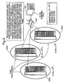
- FIG. 3 is an exemplary diagram illustrating a power domain/cluster model 300 for controlling power states according to an embodiment of the present invention.
- Power/cluster model 300 comprises a primary configuration server 302, router 204, and a plurality of power domains or clusters 304a, 304b, and 304c.
- Primary configuration server 302 is coupled to router 204.
- Router 204 is coupled to power-managed domains/clusters 304a, 304b, and 304c.
- Primary configuration server 302 distributes power/energy targets to individual power-managed domains/clusters 304a, 304b, and 304c over a predetermined interval.
- the IT infrastructure is subdivided into three (3) power-managed domains/clusters 304a, 304b, and 304c.
- three power-managed domains/clusters are shown in this example.
- Embodiments of the present invention are not limited to three power-managed domains/clusters. In fact, for any large infrastructure, more than three power-managed domains/clusters or less than three power-managed domains/clusters may be implemented.
- Power-managed domains/clusters 304a, 304b, and 304c are simply collections of machines based on locality in some context, such as, for example, physical proximity, network distance, deployment purpose, application type, etc.
- Power-managed domains/clusters 304a, 304b, and 304c may include, but are not limited to, racks of blade or modular servers in an infrastructure or datacenter, workstations, laptops, etc.
- Most systems in such environments are configured autonomously by an IT configuration server, such as, for example, primary configuration server 302, from which a local installation may be set up on individual machines, applications downloaded, configured and started. Such installation/configuration primarily occurs upon a system's entry into the infrastructure or datacenter.
- Each power domain/cluster (304a, 304b, 304c) is allocated a target power/energy consumption amount for the next interval.
- Each power domain/cluster (304a, 304b, 304c) also has a local configuration server (not explicitly shown) that operates in a similar manner to primary configuration server 302.
- the local configuration servers relay the cluster-specific energy target to its constituent nodes. The constituent nodes then adapt their configuration to meet the aggregate target energy budget.
- different energy levels can be targeted for different power-managed domains/clusters based on application type, time-of-day metrics, physical locality, etc. For example, an overall budget of 150 x 10 6 Joules is provided for all power domain/clusters 304a, 304b, and 304c.
- Primary configuration server 302 allocates energy targets to the individual power domain/clusters 304a, 304b, and 304c. In the example shown, cluster 304a is allocated an energy target of 33.33%, cluster 304b is allocated an energy target of 13.33%, and cluster 304c is allocated an energy target of 53.33% of the total targeted energy for a given interval.
- cluster 304c having the largest targeted energy allocation
- cluster 304b having the smallest targeted energy allocation
- cluster 304a having the second largest targeted energy allocation
- Embodiments of the present invention also enable allocations for power domain/clusters to be reconfigured. For example, since U.S. markets are closed at night, an abundance of market analysis may be performed during the night, and thus, cluster 304c may be allocated to market analysis while cluster 304b may be allocated to market trading.
- the amount of targeted power/energy allocated to one cluster may be reduced and that unused portion may be repurposed or transitioned to another cluster or used in some other way.
- energy/power allocated to cluster 304c may be reduced and repurposed to cluster 304b at nighttime to meet the performance requirements of heavy market analysis.
- Embodiments of the present invention enable power-managed domains/clusters 304a, 304b, and 304c to individually monitor their power/energy consumption dynamically, either through in-band or out-of-band baseboard management controllers (BMCs) or software monitors working in concert with individual components, such as processors, memory, network controllers, etc. through proprietary or standard interfaces, such as, for example a PMbus.
- BMCs baseboard management controllers
- Each of power domain/cluster 304a, 304b, and 304c relays it energy consumption over some configurable or predetermined interval.
- Each node of power domain/clusters 304a, 304b, and 304c has multiple power states, such as S-states or System states, as well as intermediate power states, such as, for example, P-states or Processor Performance states, C-states or Processor Power states, and D-states or Device states, within the S-states based on various component-specific operating levels.
- power states such as S-states or System states
- intermediate power states such as, for example, P-states or Processor Performance states, C-states or Processor Power states, and D-states or Device states
- S-states or System states are the power states that the system is in, such as, S0, S1, S2, S3, etc.
- the S0 state refers to a system state in which the system is ON
- the S3 state refers to a system state in which the system is in STANDBY, such as, for example, close your laptop without fully shutting down the system
- the S5 state refers to a system state in which the system is offline, such as, pushing the off-button on the system.
- P-states or Processor Performance states enable the processor supply voltage and frequencies to be changed. Lower voltage and/or frequencies equate to lower energy consumption and degraded performance while higher voltage and/or frequencies equate to higher energy consumption and better performance.
- C-states or Processor Power states are different power states a processor may enter into when idle. More power can be saved at the expense of additional latency as the C-state increases.
- D-states or Device states are device specific power configurations for any other devices in the system, such as, for example, I/O (Input/Output) devices.
- I/O devices may include, but are not limited to, I/O adapter cards, external memory devices, etc.
- All of the above referenced system, processor, and device states constitute a range of available power configurations that a system may be configured with to meet target power/energy budgets.
- embodiments of the present invention may utilize these states to provide numerous power configurations to achieve the target power/energy budget.
- a system in an S0 state may reduce power consumption if a processor is operating at a lower voltage and frequency as a result of a P-state transition or even a C-state transition.
- Each possible power configuration using these states is referred to as a specific system power configuration.
- each power domain/cluster Based on the target energy consumption for each power domain/cluster, such as, for example, 304a, 304b, and 304c, each power domain/cluster reconfigures its power configuration to achieve the aggregate target energy budget for each interval.
- the local configuration server aggregates the energy consumption of the entire power domain/cluster.
- the error between the targeted power/energy budget and the achieved power/energy budget is determined and the subsequent target power/energy budget for the next interval is multicast to constituent nodes directly or relayed in a peer-to-peer fashion using a feedback-driven control system.
- the sampling and control frequency may be asymmetric between the levels of the tiers or hierarchy. For example, employing a finer-grained interval, that is, shorter control interval, at the power domain/cluster level may likely improve accuracy in meeting target energy budgets, but may also increase control overhead.
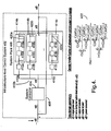
- FIG. 4 is an exemplary diagram illustrating a multi-tiered control system 400 for dynamically managing power/energy consumption for an nfrastructure according to an embodiment of the present invention.
- Control system 400 comprises an infrastructure-level control system 402 having a system controller 404, a system plant 406, and a feedback loop 408.
- System controller 404 is coupled to system plant 406, and the output of system plant 406 is fed back to system controller 404 via feedback signal 408.
- a system set point or energy target is configured for infrastructure-level control system 402 such that changing the maximum allowed energy consumption for infrastructure-level control system 402 only requires a single parameter.
- Infrastructure-level control system 402 enables administrators to configure energy targets which can be changed at any time. For example, if an HVAC system fails or a series of environmental control systems fail, the present invention may be used to set an artificially low energy target to ensure that the resultant thermal dissipation may be bound to avoid a thermally-induced emergency shutdown which is not graceful and could lead to data loss.
- System controller 404 manages the power configuration for infrastructure control system 402 based on the input into system controller 404.
- the input e(t) into system controller 404 comprises the system set point input or energy target input r(t) minus the output signal p(t) of system plant 406 which is fed back to the input using feedback loop 408, where p(t) represents the actual power consumed by system plant 406.
- the error signal, e(t) is then used to determine an energy target input for system plant 406.
- System controller 404 therefore operates to provide an optimal rate of change to achieve equilibrium, that is, an error signal, e(t), of zero (0). In other words, system controller 404 works to dissipate the error.
- System controller 404 may be a proportional controller, a proportional integral controller, a proportional integral derivative controller, or any other type of controller that exerts control to track a changing variable.
- Output signal c(t) from system controller 404 is a control signal that is fed into system plant 406.
- output signal c(t) provides an input energy target into system plant 406.
- System plant 406 comprises a plurality of nodes 410a, 410b, and 410c, each node including a weighting module 412a, 412b, and 412c and a corresponding individual control system 414a, 414b, and 414c.
- Each individual control system 414a, 414b, and 414c operates in a similar manner to infrastructure-level control system 402.
- Each weighting module and corresponding individual control system represents a power domain/cluster used within system plant 406.
- system plant 406 is shown as having three (3) individual control systems with domain weighting, one skilled in the relevant art(s) would know that more than 3 or less than 3 individual control systems with domain weighting may be used and that the actual number of individual control systems with domain weighting is directly correlated with the number of power domain/clusters used in the datacenter or IT infrastructure.
- Domain weighting modules 412a, 412b, and 412c enable each power domain/cluster to be weighted relative to the power distributed (output power c(t)) by system controller 404 amongst all power domain/clusters.
- domain weighting modules 412a, 412b, and 412c provide a quality of service scheme by permitting a datacenter or IT infrastructure to favor power distribution to systems that perform some critical function.
- power-managed domains/clusters 304a, 304b, and 304c provide domain weighting of the total targeted power/energy using weighted multipliers of 33.33%, 13.33%, and 53.33%, respectively, as shown in FIG. 3 .
- each individual control system 414a, 414b, and 414c is an error signal representing the weighted targeted power/energy level minus the actual power consumed by the corresponding power domain/cluster (the output of control systems 414a, 414b, and 414c), which is provided via a feedback loop.
- Individual control systems 414a, 414b, and 414c are used to manage the local power configuration for each power domain/cluster in the datacenter or IT infrastructure.
- Each of control systems 414a, 414b, and 414c comprises a local controller 416a, 416b, and 416c, a local system plant 418a, 418b, and 418c and a feedback loop 420a, 420b, and 420c.
- Local controller 416a, 416b, and 416c operates in a similar manner as system controller 404 described above and local system plant 418a, 418b, and 418c operates in a similar manner as system plant 406 described above. That is, control systems 414a, 414b, and 414c manage the power configuration of local system plants 418a, 418b, and 418c based on input from local controllers 416a, 416b, and 416c.
- embodiments of the present invention provide individual control systems based on different scopes that are nested within, such that the local controller output of each local control system is used as input within nested control systems.
- each level is given an energy target, which it then uses to transition the power states of specific components in all of the systems.
- the power state transitions at each node may be affected in numerous ways using a runtime agent. For example, this may be achieved in-band using a runtime OS (Operating System) daemon, firmware, or out-of-band through a baseboard management controller (BMC).
- OS Operating System
- BMC baseboard management controller
- a generic transfer function 422 is shown to describe the interaction of the nested control systems in the z-domain with respect to the output of infrastructure-level control system 402.
- control gains may be carefully chosen and analyzed for each of the levels which ensure stability despite changes in the set points at each level.
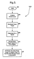
- FIG. 5 is an exemplary flow diagram 500 illustrating a method for dynamically managing power/energy consumption for an infrastructure according to an embodiment of the present invention.
- the invention is not limited to the embodiment described herein with respect to flow diagram 500. Rather, it will be apparent to persons skilled in the relevant art(s) after reading the teachings provided herein that other functional flow diagrams are within the scope of the invention.
- the process begins with block 502, where the process immediately proceeds to block 504.
- the datacenter or IT infrastructure is initialized. Initialization of the datacenter or IT infrastructure includes powering up any equipment that needs to be powered ON and enabling administrators to configure energy targets. This includes providing the domain weighting for each power-managed domain/cluster in the datacenter or IT infrastructure. This process would typically be configured by the datacenter operator (in the case of a datacenter) or a system administrator (in the case of a more general, large-scale IT deployment). Under normal conditions, once configured the system would operate autonomously. The process then proceeds to block 506.
- a set point energy target is distributed to an infrastructure-level control system for controlling power/energy consumption for the datacenter or IT infrastructure. This constitutes the primary control system.
- the process proceeds to block 508.
- an error signal is determined.
- the error signal is based upon the received set point target and an actual energy consumption of the infrastructure received during the last predetermined sampling interval. The process then proceeds to block 510.
- an adjusted energy target based on the error signal is determined.
- the adjusted energy target is determined by the infrastructure-level control system controller, such as, for example, system controller 404.
- the process then proceeds to block 512.
- the adjusted energy target or adjusted set point energy target is distributed to the system plant to enable the system plant to dynamically manage the energy consumption by transitioning the power states of specific components to meet the energy target for the system plant, and in turn, the overall infrastructure.
- the system plant actions are determined by the level within the hierarchy. For example, at the highest level, the plant might distribute updated policies to lower level controllers within the infrastructure. At an intermediate level within the hierarchy, the system plant might send updated policies to subsets of machines under its control based on the intersection of global policy sent by upper-levet controllers and local effects, such as increased thermal load on some systems. At the lowest level of the control system, the plant would affect power state transitions to meet the policy requirements sent by mid-level controllers.
- FIG. 6 is an exemplary flow diagram 600 illustrating a method for dynamically managing power/energy consumption for a system plant according to an embodiment of the present invention.
- the invention is not limited to the embodiment described herein with respect to flow diagram 600. Rather, it will be apparent to persons skilled in the relevant art(s) after reading the teachings provided herein that other functional flow diagrams are within the scope of the invention.
- the process begins with block 602, where the process immediately proceeds to block 604.
- a system plant energy target is received as input.
- the system plant energy target is the adjusted energy target sent as output from the system controller, such as, for example, system controller 404.
- the process proceeds to block 606.
- each system plant comprises a plurality of domain weighting modules coupled to a plurality of power domain/clusters modeled as and controlled by local control systems.
- the system plant energy target is weighted for each power domain/cluster in the system plant.
- the weighting enables each power domain/cluster to receive a portion of the system plant target set point.
- Such weighting policies would typically be configured by the data center operator or system administrator.
- the amount of system plant target set point apportioned to each power domain/cluster may vary depending on such factors as, for example, application-type, time-of day metrics, physical locality, etc.
- the process then proceeds to block 608.
- a local error signal is determined by each power domain/cluster based on the weighted set point for that power domain/cluster and the power consumed by the power domain/cluster during the last interval, which is provided via a local feedback loop. The process then proceeds to block 610.
- a local system controller adjusts the local error signal to provide an optimal energy target as input for the power domain/cluster. The process then proceeds to block 612.
- a power configuration based on the energy target is determined for the power-managed domain/cluster. The process proceeds to block 614.
- the power-managed domain/cluster adapts its configuration to meet the specified energy target.
- the power domain/cluster uses the optimal energy target to transition the power states of specific components within its configuration. This may include adjusting power states, such as S-states, P-states, C-states, and D-states, as described above.
- the process then proceeds to block 616.
- the system plant power output from all of the power domain/clusters is determined. This output power is provided as the feedback loop to determine the error signal for the infrastructure.
- embodiments of the present invention are not limited to one level of nested control systems.
- an energy target is given at each level.
- the energy target is then used by each level in a similar manner as that provided above, which is to transition power states of specific components in the embedded system to meet its energy target.
- power states may be changed at any time.
- FIG. 7 is a block diagram illustrating an exemplary computer system in which aspects of described embodiments may be employed.
- a computer system 700 comprises a processor 701 (also known as an in-band processor).
- Processor 701 may be connected to random access memory 705 via a memory controller hub (MCH) 703.
- MCH memory controller hub
- Processor 701 may be any type of processor capable of executing software, such as a microprocessor, digital signal processor, microcontroller, or the like.
- FIG. 7 shows only one such processor 701, there may be one or more processors in platform 700 and one or more of the processors may include multiple threads, multiple cores, or the like.
- Processor 701 may be further connected to input/output (I/O) devices via an input/output controller hub (ICH) 707.
- ICH 707 may be coupled to various devices, such as, for example, a super I/O controller (SIO), a keyboard controller (KBC), and a trusted platform module (TPM) via a low pin count (LPC) bus 702.
- SIO super I/O controller
- KBC keyboard controller
- TPM trusted platform module
- LPC low pin count
- ICH 707 is coupled to non-volatile memory via a serial peripheral interface (SPI) bus 704.
- SPI serial peripheral interface
- the non-volatile memory may be flash memory or static random access memory (SRAM) or the like.
- Computer system 700 may also include an out-of-band (OOB) microcontroller 710.
- OOB out-of-band
- OOB microcontroller 710 may connect to ICH 707 via a bus 712, typically a peripheral component interconnect (PCI) or PCI express bus. OOB microcontroller 710 may also be coupled to a non-volatile memory store (NV store) 717 via SPI bus 704. NV store 717 may be flash memory or static RAM (SRAM), or the like. In many existing systems, NV store 717 is flash memory.
- PCI peripheral component interconnect
- NV store 717 non-volatile memory store
- SRAM static RAM
- OOB microcontroller 710 may be operated to store a "message" containing a directive in a memory shared by OOB microcontroller 710 and processor 701.
- processor 701 includes a shared memory 752 which is accessible by both processor 701 and OOB microcontroller 710.
- Shared memory 752 may reside in a reserved area 752a of RAM 105, or be located in a separate non-volatile memory store 752b, or the like.
- Shared memory 752 may be operated as a mailbox for these messages.
- OOB controller 710 may store a message in shared memory 752 or retrieve a message from shared memory 752 independently of the status of processor 701, including the operating system (OS) and any other programs operating on processor 701.
- OS operating system
- OOB microcontroller 710 may store or retrieve messages in shared memory 752 whether processor 701 is being initialized or is turned off, or whether the operating system is booting, running, crashed or otherwise.
- shared memory 752 may be non-volatile (NV) memory such as flash memory or static random access memory (SRAM).
- OOB microcontroller 710 operates independently of the operating system or any system start-up program, such that OOB microcontroller 710 may have its own dedicated control circuitry, firmware, operating system, etc. to control the operations of OOB microcontroller 710 independently of the status of the remainder of computer system 700. It is appreciated that the degree of operational independence of OOB microcontroller and other components may vary, depending upon the particular application.
- OOB microcontroller 710 may be likened to a "miniature" processor. Like a full capability processor, OOB microcontroller 710 has a processor unit 711 which may be operatively coupled to a cache memory 715, as well as RAM (Random Access Memory) and ROM (Read Only Memory) memory 713. OOB microcontroller 710 may have an embedded network interface 723 and an independent connection to a power supply 725 to enable out-of-band communication even when in-band processor 701 is not active.
- inventions of the present invention may be implemented using hardware, software, or a combination thereof and may be implemented in one or more computer systems or other processing systems.
- the methods may be implemented in programs executing on programmable machines such as mobile or stationary computers, personal digital assistants (PDAs), set top boxes, cellular telephones and pagers, and other electronic devices that each include a plurality of processor cores, a storage medium readable by the processor cores (including volatile and non-volatile memory and/or storage elements), at least one input device, and one or more output devices.
- Program code is applied to the data entered using the input device to perform the functions described and to generate output information.
- the output information may be applied to one or more output devices.
- PDAs personal digital assistants
- embodiments of the invention may be practiced with various computer system configurations, including multiprocessor systems, minicomputers, mainframe computers, and the like.
- Each program may be implemented in a high level procedural or object oriented programming language to communicate with a processing system.
- programs may be implemented in assembly or machine language, if desired. In any case, the language may be compiled or interpreted.
- Program instructions may be used to cause a general-purpose or special-purpose processing system that is programmed with the instructions to perform the methods described herein. Alternatively, the methods may be performed by specific hardware components that contain hardwired logic for performing the methods, or by any combination of programmed computer components and custom hardware components.
- the methods described herein may be provided as a computer program product that may include a machine readable medium having stored thereon instructions that may be used to program a processing system or other electronic device to perform the methods.
- the term "machine readable medium” or “machine accessible medium” used herein shall include any medium that is capable of storing or encoding a sequence of instructions for execution by the machine and that causes the machine to perform any one of the methods described herein.
- machine readable medium and “machine accessible medium” shall accordingly include, but not be limited to, solid-state memories, optical and magnetic disks, and a carrier wave that encodes a data signal.
- machine readable medium and “machine accessible medium” shall accordingly include, but not be limited to, solid-state memories, optical and magnetic disks, and a carrier wave that encodes a data signal.
- software in one form or another (e.g., program, procedure, process, application, module, logic, and so on) as taking an action or causing a result. Such expressions are merely a shorthand way of stating the execution of the software by a processing system to cause the processor to perform an action or produce a result.
Landscapes
- Engineering & Computer Science (AREA)
- Theoretical Computer Science (AREA)
- General Engineering & Computer Science (AREA)
- Physics & Mathematics (AREA)
- General Physics & Mathematics (AREA)
- Computer Hardware Design (AREA)
- Power Engineering (AREA)
- Power Sources (AREA)
- Supply And Distribution Of Alternating Current (AREA)
- Mobile Radio Communication Systems (AREA)
- Data Exchanges In Wide-Area Networks (AREA)
Claims (14)
- Système de commande de distribution de puissance/énergie comprenant :un serveur de commande et de configuration de politique primaire (202 ; 302) ;un routeur en réseau (204) couplé au serveur de commande et de configuration de politique primaire ; etune pluralité de domaines/grappes à gestion de puissance (206a - 206c ; 304a - 304c) couplé(s) au routeur (204) ; oùle serveur de commande et de configuration de politique primaire (202 ; 302) est configuré pour distribuer une énergie cible à chacun(e) des domaines/grappes à gestion de puissance (206a - 206c ; 304a - 304c) sur un intervalle prédéterminé afin de permettre à chacun(e) des domaines/grappes à gestion de puissance (206a - 206c ; 304a - 304c) de gérer la consommation d'énergie pour chacun(e) des domaines/grappes à gestion de puissance (206a - 206c ; 304a - 304c) pour atteindre l'énergie cible ; etles domaines/grappes à gestion de puissance respectifs/respectives (206a - 206c ; 304a - 304c) comportent chacun(e) :une unité de commande de système (404) ; etune boucle de rétroaction (408) couplée entre une sortie du domaine/de la grappe à gestion de puissance respectif/respective (206a - 206c ; 304a - 304c) et l'unité de commande de système (404) ; oùl'unité de commande de système (404) est agencée pour recevoir une sortie de consommation de puissance atteinte par l'intermédiaire de la boucle de rétroaction (408) et est configurée pour déterminer, à la fin de chaque intervalle prédéterminé, un signal d'erreur sur la base de l'énergie cible actuelle et de la sortie de consommation de puissance atteinte reçue, afin de fournir une énergie cible réglée subséquente pour l'intervalle suivant ;caractérisé en ce que :les domaines/grappes à gestion de puissance respectifs/respectives comportent en outre chacun(e) :un serveur de configuration locale configuré pour :recevoir (604) l'énergie cible réglée ;pondérer (606) l'énergie cible réglée ;déterminer (608) une erreur locale sur la base de l'énergie cible réglée pondérée et d'une puissance consommée par le domaine/la grappe à gestion de puissance (206a - 206c ; 304a - 304c) pendant un dernier intervalle fourni par la boucle de rétroaction ;régler (610) l'erreur locale pour fournir une énergie cible optimale pour chacun(e) des domaines/grappes à gestion de puissance (206a - 206c ; 304a - 304c) ; eteffectuer une transition des états de puissance des composants spécifiques à l'intérieur des domaines/grappes à gestion de puissance (206a - 206c ; 304a - 304c) afin d'atteindre l'énergie cible optimale pour chacun(e) des domaines/grappes à gestion de puissance.
- Système de la revendication 1, dans lequel :chacun(e) des domaines/grappes à gestion de puissance (206a - 206c ; 304a - 304c) comprend en outre une pluralité de noeuds constitutifs (410a - 410c), chacun des noeuds constitutifs comprenant des serveurs, des stations de travail, des ordinateurs portables, des composants périphériques, et/ou autres composants en réseau, où le serveur de configuration locale est agencé pour recevoir une énergie cible pondérée afin de distribuer de façon dynamique la puissance à l'intérieur de la pluralité de noeuds constitutifs.
- Système de la revendication 1, dans lequel :chacun(e) des domaines/grappes à gestion de puissance (206a - 206c ; 304a - 304c) est basé(e) sur au moins l'un(e) : de la proximité physique, de la distance du réseau, du type de déploiement, et du type d'application.
- Système de la revendication 1, dans lequel :chacun(e) des domaines/grappes à gestion de puissance (206a - 206c ; 304a - 304c) comprend une baie de serveurs dans une infrastructure ou un centre de données, des stations de travail, des ordinateurs portables et autres composants.
- Système de la revendication 1, dans lequel :un(e) domaine/grappe à gestion de puissance (206a-206c ; 304a - 304c) se voit attribuer une partie de l'énergie cible pour chaque intervalle prédéterminé.
- Système de la revendication 1, dans lequel :chacun(e) des domaines/grappes à gestion de puissance (206a - 206c ; 304a - 304c) est agencé(e) pour surveiller la consommation de puissance/énergie de façon dynamique par le biais d'un démon d'OS (système d'exploitation) dans la bande, d'un microprogramme, ou d'unités de commande de gestion de la carte mère (BMC) hors bande.
- Système de la revendication 1, dans lequel:chacun(e) des domaines/grappes à gestion de puissance (206a - 206c ; 304a - 304c) comporte une pluralité de noeuds (410a - 410c), chaque noeud comportant un ou plusieurs composant(s), chaque composant comportant de multiples états de puissance pour fournir une plage de configurations de puissance disponibles que chacun(e) des domaines/grappes à gestion de puissance (206a - 206c ; 304a - 304c) utilise pour atteindre des énergies cibles ; et, éventuellement, dans lequel :les multiples états de puissance comportent :des états S, qui comprennent des états de système,des états P, qui comprennent des états de puissance qui permettent à la fréquence et à la tension d'alimentation du processeur d'être modifiées ;des états C, qui comprennent un état différent du processeur dans lequel peut entrer un processeur lorsqu'il est inactif ; etdes états D, qui comprennent des configurations de puissance spécifiques au dispositif pour tout autre composant dans le noeud.
- Système de la revendication 1, dans lequel :chacun(e) des domaines/grappes à gestion de puissance (206a - 206c ; 304a - 304c) est agencé(e) pour reconfigurer sa configuration de puissance afin d'atteindre des énergies cibles globales pour chaque intervalle prédéterminé.
- Système de la revendication 1, dans lequel :la pluralité de domaines/grappes à gestion de puissance (206a - 206c ; 304a - 304c) comprennent une pluralité de systèmes de commande adaptés pour régler et redistribuer la puissance, les systèmes de commande étant imbriqués à l'intérieur d'un système de commande de niveau d'infrastructure (402), et le système de commande de niveau d'infrastructure (402) étant configuré pour régler et redistribuer les niveaux de puissance à chacune(e) de la pluralité des domaines/grappes à gestion de puissance (206a - 206c ; 304a - 304c).
- Procédé de gestion de distribution de puissance comprenant :l'initialisation (504) d'une infrastructure ;la réception (506), par le biais d'un système de commande de niveau d'infrastructure (402), d'une énergie cible pour adapter une configuration de puissance pour l'infrastructure afin d'atteindre l'énergie cible ; etla distribution (512) de l'énergie cible à une installation de système (406) pour permettre à l'installation de système (406) de gérer de façon dynamique la consommation de puissance en effectuant la transition d'états de puissance de composants spécifiques à l'intérieur de l'infrastructure afin d'atteindre l'énergie cible pour l'installation de système (406) ;ledit procédé étant caractérisé en ce que :ladite distribution (512) de l'énergie cible à l'installation de système (406) est précédée par :la détermination (508) d'une erreur, sur la base de l'énergie cible et d'une puissance effective consommée par l'infrastructure lors d'un dernier intervalle fourni par une boucle de rétroaction (408) ; etle réglage (510) de l'énergie cible sur la base de l'erreur ;ledit procédé étant en outre caractérisé en ce que :ladite distribution (512) de l'énergie cible à l'installation de système (406) comporte :la réception (604) de l'énergie cible réglée ;la pondération (606) de l'énergie cible réglée ;la détermination (608) d'une erreur locale sur la base de l'énergie cible réglée pondérée et d'une puissance consommée par le domaine/la grappe à gestion de puissance lors d'un dernier intervalle fourni par la boucle de rétroaction ;le réglage (610) de l'erreur locale pour fournir une énergie cible optimale pour chacun(e) des domaines/grappes à gestion de puissance ; etla transition des états de puissance des composants spécifiques pour atteindre l'énergie cible optimale pour chacun(e) des domaines/grappes à gestion de puissance.
- Procédé de la revendication 10, dans lequel l'initialisation (504) de l'infrastructure comprend la mise sous tension de composants à l'intérieur de l'infrastructure et la détermination de facteurs de pondération pour les domaines/grappes à gestion de puissance à l'intérieur de l'installation de système (406).
- Procédé de la revendication 10, dans lequel la distribution (512) de l'énergie cible réglée à l'installation de système (406) comprend en outre les étapes consistant à :déterminer (616) une puissance de sortie effective de domaine/grappe à gestion de puissance pour chacun(e) des domaines/grappes à gestion de puissance ; etregrouper chacune des puissances de sortie effectives de domaines/grappes à gestion de puissance à utiliser comme rétroaction pour le système de commande de niveau d'infrastructure.
- Procédé de la revendication 12, dans lequel la transition des états de puissance des composants spécifiques pour atteindre l'énergie cible optimale pour chacun(e) des domaines/grappes à gestion de puissance comprend la transition des états S, des états P, des états C, et des états D des composants spécifiques, où :lesdits états S comprennent des états de système,lesdits états P comprennent des états de puissance qui permettent à la fréquence et à la tension d'alimentation du processeur d'être modifiées ;lesdits états C comprennent un état différent du processeur dans lequel peut entrer un processeur lorsqu'il est inactif ; etlesdits états D comprennent des configurations de puissance spécifiques au dispositif pour tout autre composant spécifique.
- Article comprenant : un support de stockage ayant une pluralité d'instructions accessibles par machine, caractérisé en ce que, lorsqu'elles sont exécutées par un processeur, ladite pluralité d'instructions accessibles par machine exécutent les étapes du procédé défini dans l'une quelconque des revendications 10-13 précédentes.
Applications Claiming Priority (1)
| Application Number | Priority Date | Filing Date | Title |
|---|---|---|---|
| US11/966,911 US8069359B2 (en) | 2007-12-28 | 2007-12-28 | System and method to establish and dynamically control energy consumption in large-scale datacenters or IT infrastructures |
Publications (3)
| Publication Number | Publication Date |
|---|---|
| EP2075666A2 EP2075666A2 (fr) | 2009-07-01 |
| EP2075666A3 EP2075666A3 (fr) | 2012-05-30 |
| EP2075666B1 true EP2075666B1 (fr) | 2014-01-22 |
Family
ID=40565121
Family Applications (1)
| Application Number | Title | Priority Date | Filing Date |
|---|---|---|---|
| EP08254170.7A Not-in-force EP2075666B1 (fr) | 2007-12-28 | 2008-12-29 | Système et procédé pour établir et contrôler dynamiquement la consommation d'énergie dans des centres de données à grande échelle ou infrastructure IT |
Country Status (4)
| Country | Link |
|---|---|
| US (2) | US8069359B2 (fr) |
| EP (1) | EP2075666B1 (fr) |
| JP (1) | JP4822165B2 (fr) |
| CN (1) | CN101472327B (fr) |
Families Citing this family (49)
| Publication number | Priority date | Publication date | Assignee | Title |
|---|---|---|---|---|
| US9003211B2 (en) * | 2007-03-20 | 2015-04-07 | Power Assure, Inc. | Method and apparatus for holistic power management to dynamically and automatically turn servers, network equipment and facility components on and off inside and across multiple data centers based on a variety of parameters without violating existing service levels |
| GB0706781D0 (en) * | 2007-04-05 | 2007-05-16 | Vodafone Plc | Telecommunications networks and devices |
| US8069359B2 (en) * | 2007-12-28 | 2011-11-29 | Intel Corporation | System and method to establish and dynamically control energy consumption in large-scale datacenters or IT infrastructures |
| US7970561B2 (en) * | 2008-04-14 | 2011-06-28 | Power Assure, Inc. | Method to calculate energy efficiency of information technology equipment |
| US8918657B2 (en) | 2008-09-08 | 2014-12-23 | Virginia Tech Intellectual Properties | Systems, devices, and/or methods for managing energy usage |
| BRPI0920495B1 (pt) * | 2009-01-31 | 2020-09-29 | Telefonaktiebolaget Lm Ericsson (Publ) | Sistema de computador e sistema para computação de consumo de energia e método para calcular energia consumida por um sistema |
| US20100217451A1 (en) * | 2009-02-24 | 2010-08-26 | Tetsuya Kouda | Energy usage control system and method |
| US8397088B1 (en) | 2009-07-21 | 2013-03-12 | The Research Foundation Of State University Of New York | Apparatus and method for efficient estimation of the energy dissipation of processor based systems |
| JP5435399B2 (ja) | 2009-10-07 | 2014-03-05 | 日本電気株式会社 | 省電力化システム、省電力化方法、及び省電力化用プログラム |
| US8201007B2 (en) * | 2010-01-06 | 2012-06-12 | Vigyanlabs Innovations Private Limited | Fine grain non-intrusive distributed information technology infrastructure power management system |
| US8356198B2 (en) | 2010-03-30 | 2013-01-15 | Hewlett-Packard Development Company, L.P. | Performing power management based on information regarding zones of devices in a system |
| US8543858B2 (en) * | 2010-04-07 | 2013-09-24 | Broadcom Corporation | System and method for managing network devices that deliver an application service using energy savings information |
| US8627118B2 (en) | 2010-05-24 | 2014-01-07 | International Business Machines Corporation | Chassis power allocation using expedited power permissions |
| US8510582B2 (en) * | 2010-07-21 | 2013-08-13 | Advanced Micro Devices, Inc. | Managing current and power in a computing system |
| US8694810B2 (en) * | 2010-09-22 | 2014-04-08 | International Business Machines Corporation | Server power management with automatically-expiring server power allocations |
| TW201222265A (en) * | 2010-11-30 | 2012-06-01 | Inventec Corp | Data center |
| CN102478905B (zh) * | 2010-11-30 | 2014-06-11 | 英业达股份有限公司 | 数据中心 |
| RU2547818C2 (ru) * | 2010-12-17 | 2015-04-10 | Сименс Акциенгезелльшафт | Система передачи энергии |
| CN102208986B (zh) * | 2011-03-22 | 2014-01-15 | 曙光信息产业(北京)有限公司 | 一种集群功耗分配与控制方法 |
| US8924752B1 (en) * | 2011-04-20 | 2014-12-30 | Apple Inc. | Power management for a graphics processing unit or other circuit |
| US8843238B2 (en) | 2011-09-30 | 2014-09-23 | Johnson Controls Technology Company | Systems and methods for controlling energy use in a building management system using energy budgets |
| US8755943B2 (en) | 2011-09-30 | 2014-06-17 | Johnson Controls Technology Company | Systems and methods for controlling energy use in a building management system using energy budgets |
| US8862909B2 (en) | 2011-12-02 | 2014-10-14 | Advanced Micro Devices, Inc. | System and method for determining a power estimate for an I/O controller based on monitored activity levels and adjusting power limit of processing units by comparing the power estimate with an assigned power limit for the I/O controller |
| US8924758B2 (en) | 2011-12-13 | 2014-12-30 | Advanced Micro Devices, Inc. | Method for SOC performance and power optimization |
| KR101425117B1 (ko) | 2011-12-26 | 2014-08-01 | 주식회사 케이티 | 인터넷 데이터 센터의 전력 공급 시스템 및 이를 이용한 전력 관리 방법 |
| WO2013176651A1 (fr) | 2012-05-21 | 2013-11-28 | New Jersey Institute Of Technology | Optimisation d'énergie hiérarchique pour réseaux de centres de données |
| US9342376B2 (en) | 2012-06-27 | 2016-05-17 | Intel Corporation | Method, system, and device for dynamic energy efficient job scheduling in a cloud computing environment |
| US9298247B2 (en) * | 2012-11-27 | 2016-03-29 | International Business Machines Corporation | Distributed power budgeting |
| CN105074653B (zh) | 2013-03-28 | 2018-11-23 | 慧与发展有限责任合伙企业 | 使计算刀片设备和扩展刀片设备的存储器可供由操作系统使用 |
| WO2014158161A1 (fr) | 2013-03-28 | 2014-10-02 | Hewlett-Packard Development Company, L.P. | Message de coordination d'erreur pour un dispositif lame ayant un processeur logique dans un autre domaine de micrologiciel système |
| CN105103121B (zh) | 2013-03-28 | 2018-10-26 | 慧与发展有限责任合伙企业 | 刀片系统以及刀片系统的分区执行方法 |
| BR112015029424B1 (pt) * | 2013-05-30 | 2021-07-13 | Toshiba Mitsubishi-Electric Industrial Systems Corporation | Dispositivo de gestão de energia |
| US9172718B2 (en) * | 2013-09-25 | 2015-10-27 | International Business Machines Corporation | Endpoint load rebalancing controller |
| JP6483142B2 (ja) * | 2014-03-14 | 2019-03-13 | グーグル エルエルシー | 周辺機器デバイスのユニバーサルシリアルバスエミュレーション |
| WO2015198286A1 (fr) | 2014-06-26 | 2015-12-30 | Consiglio Nazionale Delle Ricerche | Procédé et système pour réguler en temps réel les fréquences d'horloge d'au moins un groupe de machines électroniques |
| EP3175415B1 (fr) * | 2014-08-19 | 2017-12-20 | Origami Energy Limited | Système de commande de distribution d'énergie |
| US9477281B2 (en) | 2014-09-12 | 2016-10-25 | Vigyanlabs Inc. | Distributed information technology infrastructure dynamic policy driven peak power management system |
| US10606642B1 (en) * | 2014-09-16 | 2020-03-31 | Amazon Technologies, Inc. | Dynamic power budgets |
| US10620687B2 (en) * | 2014-12-22 | 2020-04-14 | Intel Corporation | Hybrid power management approach |
| US9753526B2 (en) | 2014-12-23 | 2017-09-05 | Intel Corporation | Systems and methods for synergistic software-hardware power budget management |
| US9829902B2 (en) * | 2014-12-23 | 2017-11-28 | Intel Corporation | Systems and methods for dynamic temporal power steering |
| US9948512B2 (en) | 2016-01-14 | 2018-04-17 | Veniam, Inc. | Systems and methods for remote configuration update and distribution in a network of moving things |
| US9763188B2 (en) * | 2015-12-31 | 2017-09-12 | Veniam, Inc. | Systems and methods for reconfiguring and adapting hardware in the network of moving things |
| US10216245B2 (en) | 2015-12-22 | 2019-02-26 | Cray Inc. | Application ramp rate control in large installations |
| DE102016200033A1 (de) * | 2016-01-05 | 2017-07-06 | Deutsche Telekom Ag | Verfahren und Systeme zum effizienten Speichern und/oder Bearbeiten von Daten und/oder Verarbeiten von Prozessen |
| US10091733B2 (en) * | 2016-02-16 | 2018-10-02 | Veniam, Inc. | Systems and methods for power management in a network of moving things, for example including a network of autonomous vehicles |
| US10948957B1 (en) * | 2019-09-26 | 2021-03-16 | Apple Inc. | Adaptive on-chip digital power estimator |
| CN111107619B (zh) * | 2019-12-27 | 2023-05-16 | 深圳市联洲国际技术有限公司 | 一种通信系统的功率控制方法、通信系统及存储介质 |
| US12475072B2 (en) * | 2023-06-30 | 2025-11-18 | Dell Products, L.P. | Network connectivity for out-of-band processors in heterogeneous computing platforms |
Family Cites Families (20)
| Publication number | Priority date | Publication date | Assignee | Title |
|---|---|---|---|---|
| CN1120555C (zh) * | 1995-02-25 | 2003-09-03 | 国电自动化研究院 | 电力系统的自适应系统保护方法 |
| US7249043B1 (en) * | 2000-03-10 | 2007-07-24 | E.P.M., Inc. | Computer program and method for reducing HVAC demand for energy |
| US6836849B2 (en) * | 2001-04-05 | 2004-12-28 | International Business Machines Corporation | Method and apparatus for controlling power and performance in a multiprocessing system according to customer level operational requirements |
| US6832134B2 (en) * | 2002-11-12 | 2004-12-14 | Honeywell International Inc. | Coordination in multilayer process control and optimization schemes |
| US7051215B2 (en) * | 2003-06-13 | 2006-05-23 | Intel Corporation | Power management for clustered computing platforms |
| JP4338126B2 (ja) | 2003-08-06 | 2009-10-07 | インターナショナル・ビジネス・マシーンズ・コーポレーション | ネットワークシステム、サーバ、機器管理方法およびプログラム |
| JP2005086972A (ja) * | 2003-09-11 | 2005-03-31 | Fuji Electric Fa Components & Systems Co Ltd | デマンド制御装置 |
| US7240225B2 (en) * | 2003-11-10 | 2007-07-03 | Dell Products L.P. | System and method for throttling power in one or more information handling systems |
| US7305569B2 (en) | 2004-06-29 | 2007-12-04 | Intel Corporation | Apparatus, system and method for adjusting a set of actual power states according to a function depending on a set of desired power states |
| US20060156041A1 (en) * | 2005-01-07 | 2006-07-13 | Lee Zaretsky | System and method for power management of plural information handling systems |
| JP4591149B2 (ja) * | 2005-03-29 | 2010-12-01 | 日本電気株式会社 | クラスタシステム、ブレードサーバの電源制御方法及びそのプログラム |
| US7461273B2 (en) * | 2005-05-16 | 2008-12-02 | Hewlett-Packard Development Company, L.P. | Power distribution among servers |
| US7581125B2 (en) * | 2005-09-22 | 2009-08-25 | Hewlett-Packard Development Company, L.P. | Agent for managing power among electronic systems |
| US7350090B2 (en) * | 2005-10-11 | 2008-03-25 | Dell Products L.P. | Ensuring power availability to a blade server when blade management controller is corrupted |
| JP2007213167A (ja) | 2006-02-07 | 2007-08-23 | Fujitsu Ltd | 電力制御プログラム、サーバシステム、および電力制御方法 |
| US7555666B2 (en) * | 2006-05-04 | 2009-06-30 | Dell Products L.P. | Power profiling application for managing power allocation in an information handling system |
| US7669071B2 (en) * | 2006-05-05 | 2010-02-23 | Dell Products L.P. | Power allocation management in an information handling system |
| US7702931B2 (en) * | 2006-06-27 | 2010-04-20 | Hewlett-Packard Development Company, L.P. | Adjusting power budgets of multiple servers |
| US7779276B2 (en) * | 2007-03-05 | 2010-08-17 | International Business Machines Corporation | Power management in a power-constrained processing system |
| US8069359B2 (en) | 2007-12-28 | 2011-11-29 | Intel Corporation | System and method to establish and dynamically control energy consumption in large-scale datacenters or IT infrastructures |
-
2007
- 2007-12-28 US US11/966,911 patent/US8069359B2/en not_active Expired - Fee Related
-
2008
- 2008-12-24 JP JP2008327065A patent/JP4822165B2/ja not_active Expired - Fee Related
- 2008-12-29 CN CN2008101847306A patent/CN101472327B/zh not_active Expired - Fee Related
- 2008-12-29 EP EP08254170.7A patent/EP2075666B1/fr not_active Not-in-force
-
2011
- 2011-10-20 US US13/277,432 patent/US8301925B2/en not_active Expired - Fee Related
Also Published As
| Publication number | Publication date |
|---|---|
| EP2075666A3 (fr) | 2012-05-30 |
| US20090171511A1 (en) | 2009-07-02 |
| CN101472327A (zh) | 2009-07-01 |
| JP2009181571A (ja) | 2009-08-13 |
| US8069359B2 (en) | 2011-11-29 |
| US20120036377A1 (en) | 2012-02-09 |
| US8301925B2 (en) | 2012-10-30 |
| CN101472327B (zh) | 2013-06-19 |
| EP2075666A2 (fr) | 2009-07-01 |
| JP4822165B2 (ja) | 2011-11-24 |
Similar Documents
| Publication | Publication Date | Title |
|---|---|---|
| EP2075666B1 (fr) | Système et procédé pour établir et contrôler dynamiquement la consommation d'énergie dans des centres de données à grande échelle ou infrastructure IT | |
| Brown et al. | Toward energy-efficient computing | |
| US10289184B2 (en) | Methods of achieving cognizant power management | |
| US7421599B2 (en) | Power management server and method for managing power consumption | |
| US7992021B2 (en) | Power-managed server and method for managing power consumption | |
| US9939834B2 (en) | Control of power consumption | |
| US8051316B2 (en) | System and method for managing power supply units | |
| CN1969248B (zh) | 用于管理服务器的功耗的方法和装置 | |
| US7721125B2 (en) | System, method, and architecture for dynamic server power management and dynamic workload management for multi-server environment | |
| US9261945B2 (en) | Dynanmic peak power limiting to processing nodes in an information handling system | |
| US8041967B2 (en) | System and method for controlling power to resources based on historical utilization data | |
| US6986069B2 (en) | Methods and apparatus for static and dynamic power management of computer systems | |
| US8006112B2 (en) | System and method for managing blades after a power supply unit failure | |
| US20140359323A1 (en) | System and method for closed loop physical resource control in large, multiple-processor installations | |
| WO2008016613A2 (fr) | Système de régulation d'ordinateur à surveillance et régulation automatique de la consommation électrique | |
| EP4027241A1 (fr) | Procédé et système permettant d'optimiser des ressources de serveur de bâti de support | |
| EP2607987A1 (fr) | Appareil informatique et système de contrôle à distance des états de fonctionnement | |
| JP2004078940A (ja) | マルチプロセッサ・コンピュータシステム内のプロセッサの電圧を管理する方法 | |
| GB2392267A (en) | Voltage management in a multiprocessor system. | |
| JP2004078935A (ja) | ブレード型アーキテクチャ・システム内のブレードの動作電圧を管理する方法 | |
| US20100100756A1 (en) | Power Supply Wear Leveling in a Multiple-PSU Information Handling System | |
| CN105549723A (zh) | 一种服务器节电控制方法、装置及电子设备节电控制装置 | |
| Yin et al. | Copa: Highly cost-effective power back-up for green datacenters |
Legal Events
| Date | Code | Title | Description |
|---|---|---|---|
| PUAI | Public reference made under article 153(3) epc to a published international application that has entered the european phase |
Free format text: ORIGINAL CODE: 0009012 |
|
| 17P | Request for examination filed |
Effective date: 20090113 |
|
| AK | Designated contracting states |
Kind code of ref document: A2 Designated state(s): AT BE BG CH CY CZ DE DK EE ES FI FR GB GR HR HU IE IS IT LI LT LU LV MC MT NL NO PL PT RO SE SI SK TR |
|
| AX | Request for extension of the european patent |
Extension state: AL BA MK RS |
|
| PUAL | Search report despatched |
Free format text: ORIGINAL CODE: 0009013 |
|
| AK | Designated contracting states |
Kind code of ref document: A3 Designated state(s): AT BE BG CH CY CZ DE DK EE ES FI FR GB GR HR HU IE IS IT LI LT LU LV MC MT NL NO PL PT RO SE SI SK TR |
|
| AX | Request for extension of the european patent |
Extension state: AL BA MK RS |
|
| RIC1 | Information provided on ipc code assigned before grant |
Ipc: H02J 1/14 20060101ALI20120424BHEP Ipc: G06F 1/32 20060101ALI20120424BHEP Ipc: G06F 1/26 20060101AFI20120424BHEP |
|
| 17Q | First examination report despatched |
Effective date: 20120625 |
|
| AKX | Designation fees paid |
Designated state(s): AT BE BG CH CY CZ DE DK EE ES FI FR GB GR HR HU IE IS IT LI LT LU LV MC MT NL NO PL PT RO SE SI SK TR |
|
| GRAP | Despatch of communication of intention to grant a patent |
Free format text: ORIGINAL CODE: EPIDOSNIGR1 |
|
| INTG | Intention to grant announced |
Effective date: 20130709 |
|
| GRAS | Grant fee paid |
Free format text: ORIGINAL CODE: EPIDOSNIGR3 |
|
| GRAA | (expected) grant |
Free format text: ORIGINAL CODE: 0009210 |
|
| AK | Designated contracting states |
Kind code of ref document: B1 Designated state(s): AT BE BG CH CY CZ DE DK EE ES FI FR GB GR HR HU IE IS IT LI LT LU LV MC MT NL NO PL PT RO SE SI SK TR |
|
| REG | Reference to a national code |
Ref country code: GB Ref legal event code: FG4D |
|
| REG | Reference to a national code |
Ref country code: CH Ref legal event code: EP |
|
| REG | Reference to a national code |
Ref country code: AT Ref legal event code: REF Ref document number: 651073 Country of ref document: AT Kind code of ref document: T Effective date: 20140215 |
|
| REG | Reference to a national code |
Ref country code: IE Ref legal event code: FG4D |
|
| REG | Reference to a national code |
Ref country code: DE Ref legal event code: R096 Ref document number: 602008030055 Country of ref document: DE Effective date: 20140306 |
|
| REG | Reference to a national code |
Ref country code: NL Ref legal event code: VDEP Effective date: 20140122 |
|
| REG | Reference to a national code |
Ref country code: AT Ref legal event code: MK05 Ref document number: 651073 Country of ref document: AT Kind code of ref document: T Effective date: 20140122 |
|
| REG | Reference to a national code |
Ref country code: LT Ref legal event code: MG4D |
|
| PG25 | Lapsed in a contracting state [announced via postgrant information from national office to epo] |
Ref country code: IS Free format text: LAPSE BECAUSE OF FAILURE TO SUBMIT A TRANSLATION OF THE DESCRIPTION OR TO PAY THE FEE WITHIN THE PRESCRIBED TIME-LIMIT Effective date: 20140522 Ref country code: LT Free format text: LAPSE BECAUSE OF FAILURE TO SUBMIT A TRANSLATION OF THE DESCRIPTION OR TO PAY THE FEE WITHIN THE PRESCRIBED TIME-LIMIT Effective date: 20140122 Ref country code: NO Free format text: LAPSE BECAUSE OF FAILURE TO SUBMIT A TRANSLATION OF THE DESCRIPTION OR TO PAY THE FEE WITHIN THE PRESCRIBED TIME-LIMIT Effective date: 20140422 |
|
| PG25 | Lapsed in a contracting state [announced via postgrant information from national office to epo] |
Ref country code: ES Free format text: LAPSE BECAUSE OF FAILURE TO SUBMIT A TRANSLATION OF THE DESCRIPTION OR TO PAY THE FEE WITHIN THE PRESCRIBED TIME-LIMIT Effective date: 20140122 Ref country code: FI Free format text: LAPSE BECAUSE OF FAILURE TO SUBMIT A TRANSLATION OF THE DESCRIPTION OR TO PAY THE FEE WITHIN THE PRESCRIBED TIME-LIMIT Effective date: 20140122 Ref country code: SE Free format text: LAPSE BECAUSE OF FAILURE TO SUBMIT A TRANSLATION OF THE DESCRIPTION OR TO PAY THE FEE WITHIN THE PRESCRIBED TIME-LIMIT Effective date: 20140122 Ref country code: CY Free format text: LAPSE BECAUSE OF FAILURE TO SUBMIT A TRANSLATION OF THE DESCRIPTION OR TO PAY THE FEE WITHIN THE PRESCRIBED TIME-LIMIT Effective date: 20140122 Ref country code: AT Free format text: LAPSE BECAUSE OF FAILURE TO SUBMIT A TRANSLATION OF THE DESCRIPTION OR TO PAY THE FEE WITHIN THE PRESCRIBED TIME-LIMIT Effective date: 20140122 Ref country code: PT Free format text: LAPSE BECAUSE OF FAILURE TO SUBMIT A TRANSLATION OF THE DESCRIPTION OR TO PAY THE FEE WITHIN THE PRESCRIBED TIME-LIMIT Effective date: 20140522 Ref country code: NL Free format text: LAPSE BECAUSE OF FAILURE TO SUBMIT A TRANSLATION OF THE DESCRIPTION OR TO PAY THE FEE WITHIN THE PRESCRIBED TIME-LIMIT Effective date: 20140122 |
|
| PG25 | Lapsed in a contracting state [announced via postgrant information from national office to epo] |
Ref country code: HR Free format text: LAPSE BECAUSE OF FAILURE TO SUBMIT A TRANSLATION OF THE DESCRIPTION OR TO PAY THE FEE WITHIN THE PRESCRIBED TIME-LIMIT Effective date: 20140122 Ref country code: BE Free format text: LAPSE BECAUSE OF FAILURE TO SUBMIT A TRANSLATION OF THE DESCRIPTION OR TO PAY THE FEE WITHIN THE PRESCRIBED TIME-LIMIT Effective date: 20140122 Ref country code: LV Free format text: LAPSE BECAUSE OF FAILURE TO SUBMIT A TRANSLATION OF THE DESCRIPTION OR TO PAY THE FEE WITHIN THE PRESCRIBED TIME-LIMIT Effective date: 20140122 |
|
| REG | Reference to a national code |
Ref country code: DE Ref legal event code: R097 Ref document number: 602008030055 Country of ref document: DE |
|
| PG25 | Lapsed in a contracting state [announced via postgrant information from national office to epo] |
Ref country code: DK Free format text: LAPSE BECAUSE OF FAILURE TO SUBMIT A TRANSLATION OF THE DESCRIPTION OR TO PAY THE FEE WITHIN THE PRESCRIBED TIME-LIMIT Effective date: 20140122 Ref country code: CZ Free format text: LAPSE BECAUSE OF FAILURE TO SUBMIT A TRANSLATION OF THE DESCRIPTION OR TO PAY THE FEE WITHIN THE PRESCRIBED TIME-LIMIT Effective date: 20140122 Ref country code: EE Free format text: LAPSE BECAUSE OF FAILURE TO SUBMIT A TRANSLATION OF THE DESCRIPTION OR TO PAY THE FEE WITHIN THE PRESCRIBED TIME-LIMIT Effective date: 20140122 Ref country code: RO Free format text: LAPSE BECAUSE OF FAILURE TO SUBMIT A TRANSLATION OF THE DESCRIPTION OR TO PAY THE FEE WITHIN THE PRESCRIBED TIME-LIMIT Effective date: 20140122 |
|
| PG25 | Lapsed in a contracting state [announced via postgrant information from national office to epo] |
Ref country code: SK Free format text: LAPSE BECAUSE OF FAILURE TO SUBMIT A TRANSLATION OF THE DESCRIPTION OR TO PAY THE FEE WITHIN THE PRESCRIBED TIME-LIMIT Effective date: 20140122 Ref country code: PL Free format text: LAPSE BECAUSE OF FAILURE TO SUBMIT A TRANSLATION OF THE DESCRIPTION OR TO PAY THE FEE WITHIN THE PRESCRIBED TIME-LIMIT Effective date: 20140122 |
|
| PLBE | No opposition filed within time limit |
Free format text: ORIGINAL CODE: 0009261 |
|
| STAA | Information on the status of an ep patent application or granted ep patent |
Free format text: STATUS: NO OPPOSITION FILED WITHIN TIME LIMIT |
|
| 26N | No opposition filed |
Effective date: 20141023 |
|
| REG | Reference to a national code |
Ref country code: DE Ref legal event code: R097 Ref document number: 602008030055 Country of ref document: DE Effective date: 20141023 |
|
| PG25 | Lapsed in a contracting state [announced via postgrant information from national office to epo] |
Ref country code: SI Free format text: LAPSE BECAUSE OF FAILURE TO SUBMIT A TRANSLATION OF THE DESCRIPTION OR TO PAY THE FEE WITHIN THE PRESCRIBED TIME-LIMIT Effective date: 20140122 |
|
| PG25 | Lapsed in a contracting state [announced via postgrant information from national office to epo] |
Ref country code: LU Free format text: LAPSE BECAUSE OF FAILURE TO SUBMIT A TRANSLATION OF THE DESCRIPTION OR TO PAY THE FEE WITHIN THE PRESCRIBED TIME-LIMIT Effective date: 20141229 |
|
| REG | Reference to a national code |
Ref country code: CH Ref legal event code: PL |
|
| REG | Reference to a national code |
Ref country code: IE Ref legal event code: MM4A |
|
| REG | Reference to a national code |
Ref country code: FR Ref legal event code: ST Effective date: 20150831 |
|
| PG25 | Lapsed in a contracting state [announced via postgrant information from national office to epo] |
Ref country code: LI Free format text: LAPSE BECAUSE OF NON-PAYMENT OF DUE FEES Effective date: 20141231 Ref country code: IE Free format text: LAPSE BECAUSE OF NON-PAYMENT OF DUE FEES Effective date: 20141229 Ref country code: CH Free format text: LAPSE BECAUSE OF NON-PAYMENT OF DUE FEES Effective date: 20141231 |
|
| PG25 | Lapsed in a contracting state [announced via postgrant information from national office to epo] |
Ref country code: FR Free format text: LAPSE BECAUSE OF NON-PAYMENT OF DUE FEES Effective date: 20141231 |
|
| PG25 | Lapsed in a contracting state [announced via postgrant information from national office to epo] |
Ref country code: MC Free format text: LAPSE BECAUSE OF FAILURE TO SUBMIT A TRANSLATION OF THE DESCRIPTION OR TO PAY THE FEE WITHIN THE PRESCRIBED TIME-LIMIT Effective date: 20140122 Ref country code: BG Free format text: LAPSE BECAUSE OF FAILURE TO SUBMIT A TRANSLATION OF THE DESCRIPTION OR TO PAY THE FEE WITHIN THE PRESCRIBED TIME-LIMIT Effective date: 20140122 |
|
| PG25 | Lapsed in a contracting state [announced via postgrant information from national office to epo] |
Ref country code: GR Free format text: LAPSE BECAUSE OF FAILURE TO SUBMIT A TRANSLATION OF THE DESCRIPTION OR TO PAY THE FEE WITHIN THE PRESCRIBED TIME-LIMIT Effective date: 20140423 Ref country code: IT Free format text: LAPSE BECAUSE OF FAILURE TO SUBMIT A TRANSLATION OF THE DESCRIPTION OR TO PAY THE FEE WITHIN THE PRESCRIBED TIME-LIMIT Effective date: 20140122 |
|
| PG25 | Lapsed in a contracting state [announced via postgrant information from national office to epo] |
Ref country code: HU Free format text: LAPSE BECAUSE OF FAILURE TO SUBMIT A TRANSLATION OF THE DESCRIPTION OR TO PAY THE FEE WITHIN THE PRESCRIBED TIME-LIMIT; INVALID AB INITIO Effective date: 20081229 Ref country code: MT Free format text: LAPSE BECAUSE OF FAILURE TO SUBMIT A TRANSLATION OF THE DESCRIPTION OR TO PAY THE FEE WITHIN THE PRESCRIBED TIME-LIMIT Effective date: 20140122 Ref country code: TR Free format text: LAPSE BECAUSE OF FAILURE TO SUBMIT A TRANSLATION OF THE DESCRIPTION OR TO PAY THE FEE WITHIN THE PRESCRIBED TIME-LIMIT Effective date: 20140122 |
|
| PGFP | Annual fee paid to national office [announced via postgrant information from national office to epo] |
Ref country code: DE Payment date: 20181218 Year of fee payment: 11 |
|
| PGFP | Annual fee paid to national office [announced via postgrant information from national office to epo] |
Ref country code: GB Payment date: 20181227 Year of fee payment: 11 |
|
| REG | Reference to a national code |
Ref country code: DE Ref legal event code: R119 Ref document number: 602008030055 Country of ref document: DE |
|
| GBPC | Gb: european patent ceased through non-payment of renewal fee |
Effective date: 20191229 |
|
| PG25 | Lapsed in a contracting state [announced via postgrant information from national office to epo] |
Ref country code: DE Free format text: LAPSE BECAUSE OF NON-PAYMENT OF DUE FEES Effective date: 20200701 Ref country code: GB Free format text: LAPSE BECAUSE OF NON-PAYMENT OF DUE FEES Effective date: 20191229 |