EP2075723A2 - Ultraschallsystem und Verfahren zum Erzeugen von Ultraschallbildsignalen mit Simultanverarbeitung - Google Patents
Ultraschallsystem und Verfahren zum Erzeugen von Ultraschallbildsignalen mit Simultanverarbeitung Download PDFInfo
- Publication number
- EP2075723A2 EP2075723A2 EP08022483A EP08022483A EP2075723A2 EP 2075723 A2 EP2075723 A2 EP 2075723A2 EP 08022483 A EP08022483 A EP 08022483A EP 08022483 A EP08022483 A EP 08022483A EP 2075723 A2 EP2075723 A2 EP 2075723A2
- Authority
- EP
- European Patent Office
- Prior art keywords
- signals
- ultrasound
- image
- scan line
- processors
- Prior art date
- Legal status (The legal status is an assumption and is not a legal conclusion. Google has not performed a legal analysis and makes no representation as to the accuracy of the status listed.)
- Withdrawn
Links
Images

Classifications
-
- A—HUMAN NECESSITIES
- A61—MEDICAL OR VETERINARY SCIENCE; HYGIENE
- A61B—DIAGNOSIS; SURGERY; IDENTIFICATION
- A61B8/00—Diagnosis using ultrasonic, sonic or infrasonic waves
- A61B8/13—Tomography
- A61B8/14—Echo-tomography
-
- A—HUMAN NECESSITIES
- A61—MEDICAL OR VETERINARY SCIENCE; HYGIENE
- A61B—DIAGNOSIS; SURGERY; IDENTIFICATION
- A61B8/00—Diagnosis using ultrasonic, sonic or infrasonic waves
-
- G—PHYSICS
- G16—INFORMATION AND COMMUNICATION TECHNOLOGY [ICT] SPECIALLY ADAPTED FOR SPECIFIC APPLICATION FIELDS
- G16H—HEALTHCARE INFORMATICS, i.e. INFORMATION AND COMMUNICATION TECHNOLOGY [ICT] SPECIALLY ADAPTED FOR THE HANDLING OR PROCESSING OF MEDICAL OR HEALTHCARE DATA
- G16H30/00—ICT specially adapted for the handling or processing of medical images
- G16H30/20—ICT specially adapted for the handling or processing of medical images for handling medical images, e.g. DICOM, HL7 or PACS
-
- G—PHYSICS
- G16—INFORMATION AND COMMUNICATION TECHNOLOGY [ICT] SPECIALLY ADAPTED FOR SPECIFIC APPLICATION FIELDS
- G16H—HEALTHCARE INFORMATICS, i.e. INFORMATION AND COMMUNICATION TECHNOLOGY [ICT] SPECIALLY ADAPTED FOR THE HANDLING OR PROCESSING OF MEDICAL OR HEALTHCARE DATA
- G16H40/00—ICT specially adapted for the management or administration of healthcare resources or facilities; ICT specially adapted for the management or operation of medical equipment or devices
- G16H40/60—ICT specially adapted for the management or administration of healthcare resources or facilities; ICT specially adapted for the management or operation of medical equipment or devices for the operation of medical equipment or devices
- G16H40/63—ICT specially adapted for the management or administration of healthcare resources or facilities; ICT specially adapted for the management or operation of medical equipment or devices for the operation of medical equipment or devices for local operation
-
- G—PHYSICS
- G16—INFORMATION AND COMMUNICATION TECHNOLOGY [ICT] SPECIALLY ADAPTED FOR SPECIFIC APPLICATION FIELDS
- G16H—HEALTHCARE INFORMATICS, i.e. INFORMATION AND COMMUNICATION TECHNOLOGY [ICT] SPECIALLY ADAPTED FOR THE HANDLING OR PROCESSING OF MEDICAL OR HEALTHCARE DATA
- G16H50/00—ICT specially adapted for medical diagnosis, medical simulation or medical data mining; ICT specially adapted for detecting, monitoring or modelling epidemics or pandemics
- G16H50/20—ICT specially adapted for medical diagnosis, medical simulation or medical data mining; ICT specially adapted for detecting, monitoring or modelling epidemics or pandemics for computer-aided diagnosis, e.g. based on medical expert systems
Definitions
- the present invention generally relates to ultrasound systems, and more particularly to an ultrasound system and a method of forming ultrasound image signals with multiprocessing.
- An ultrasound system has become an important and popular diagnostic tool due to its non-invasive and non-destructive nature.
- Modem high-performance ultrasound imaging diagnostic devices and techniques are commonly used to produce two- or three-dimensional images of internal features of patients.
- the ultrasound system may include a transducer for generating ultrasound signals in response to electrical pulse signals and converting ultrasound echoes reflected from a target object into electrical receive signals.
- the ultrasound system may further include separate image processing modules such as a beam forming application specific integrated circuit (ASIC), a signal processing ASIC, a digital signal processing chip and the like.
- the image processing modules may sequentially process the receive signals outputted from the transducer in a pipeline manner, thereby obtaining ultrasound image signals-However, the use of the separate hardware-based image processing modules is not economical Also, it may be difficult to miniaturize the ultrasound system as well as to maintain and manage the ultrasound system.
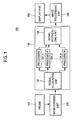
- FIG. 1 is a block diagram showing an illustrative embodiment of an ultrasound system.
- FIG. 2 is a schematic diagram showing an example of dividing scan line signals by a signal allocating unit.
- FIG. 1 is a block diagram showing an illustrative embodiment of an ultrasound system.
- the ultrasound system 100 may include a probe for transmitting and receiving ultrasound signals.
- the probe may include an array transducer comprising a plurality of elements
- the elements may be formed with a piezoelectric material adapted to reciprocally convert electrical signals and ultrasound signals.
- the elements may generate ultrasound signals in response to electrical pulse signals provided from pulsers (not shown).
- the ultrasound signals may be transmitted along a plurality of scan lines.
- the transduce elements may convert ultrasound echoes reflected from a target object into electrical receive signals.
- the transducer elements may output the receive signals through channels.
- the ultrasound system 100 may further include a beam forming unit 120, which may be configured to delay the receive signals inputted through the channels in consideration of distances between the elements and focal points.
- the beam forming unit 120 may be further configured to sum the delayed receive signals, thereby forming raw signals corresponding to the respective scan lines (hereinafter referred to as "scan line signals").
- the ultrasound system 100 may further include a multiprocessing unit 130 configured to process the scan line signals in order to form ultrasound image signals.
- the multiprocessing unit 130 may include a signal allocating unit 132, a plurality of processors 134_1-134_n and a signal synthesizing unit 136.
- the signal allocating unit 132 may divide the scan line signals into a plurality of groups to allocate the scan line signals to the processors 134_1-134_n, as illustrated in FIG. 2 .
- the number of groups may be determine depending on the number of processors 134_1-134_n. Assuming that the total number of scan lines is "S,” the number of scan lines "k" associated with the scan line signals included in each of the groups may be computed by using the following equation (1).
- Each of the processors 134_1-134_n may receive the scan line signals associate with the k scan lines allocated by the signal allocating unit 132. Each of the processors 134_1-134_n may be configured to process the scan line signals to form sub-image signals.
- the processors 134_1-134_n may amplify the scan line signals so as to have amplitudes suitable for image processing in the ultrasound system 100.
- the processors 134_1-134_n may be further configured to perform compensation for the attenuation losses in the amplified signals.
- the processors 134_1-134_n may compress the amplified signals so as to have a dynamic range of a display unit and demodulate compressed signals into single pulse signals or spike signals. Further, the processors 134_1-134_n may be configured to perform a reject control for removing noise signals from the demodulated signals to thereby form the sub-image signals.
- multiprocessing is achieved by the separate processors 134_1-134_n, the multiprocessing may be achieved by a multi core processor in anther embodiment of the present invention.
- the signal synthesizing unit 136 may be configured to synthesize the sub-image signals outputted from the processors 134_1-134_n, thereby outputting the ultrasound image signals corresponding to an image frame.
- the multiprocessing unit 130 may further include a memory (not shown). The memory may store software algorithms necessary for processing the scan line signals.
- the ultrasound system 100 may further include an image processing unit 140-The image processing unit 140 may be configured to perform image processing upon the ultrasound image signals for display. For example, the image processing unit 140 may scan-convert the ultrasound image signals into an image format suitable for display. The image processing unit 140 may be further configured to render the scan-converted ultrasound image signals to form pixel data.
- the ultrasound system 100 may also include a display unit 150 for displaying an ultrasound image on a screen based on the pixel data.
- each of the processors 134_1-134_n may scan convert the sub-image signals and the signals synthesizing unit 136 may synthesize the sub-image signals, which are scan converted.
- the image processing unit 140 may be further configured to tender the ultrasound image signals to form pixel data without performing the scan conversion.
- the ultrasound system 100 may operate in a duplex mode for providing two or more different mode images, e.g., a B-mode image and a power Doppler mode image at the same time. Amounts and operations for processing the image data for the respective diagnostic modes may be different from each other.
- the processors 134_1-134_n may be divided into a plurality of processor groups depending on the number of diagnostic modes. Assuming that a B mode image and a power Doppler mode image are formed in the duplex mode, for example, the processors 134_1-134_n may be divided into a first processor group including the processors 134_1-134_m and a second processor group including the processors 134_m+1-134_n.
- the first processor group may operate to form the B mode image and the second processor group may operate to form the power Doppler mode image. That is, the signal allocating unit 132 may be configured to allocate scan line signals corresponding to the B mode to the first processor group and scan line signals corresponding to the power Doppler mode to the second processor group.
- the image synthesizing unit 140 may be configured to synthesize sub-image signals outputted from the first processor group to thereby form a set of ultrasound image signal corresponding to a B mode image frame. Also, the image synthesizing unit 140 may synthesize sub-image signals outputted from the second processor group to thereby form a set of ultrasound image signal corresponding to the power Doppler mode image frame.
- the duplex mode includes a B-mode and a PD mode in one embodiment, the diagnostic modes included in the duplex mode are not limited thereto.
- the duplex mode may include two modes selected from a B mode, a C mode, an M mode, a PW mode, a CW mode, a 3-dimensional mode and the like.
- the performance for processing the scan line signals may be improved. Also, since the hardware-based image processing modules such as the beam forming ASIC, signal processing ASIC, DSP chip, etc. are not required, the costs may be saved and the ultrasound system may be miniaturized- Further since the image processing is carried out by the software, an enhance image may be obtained.
- an ultrasound system comprising: a probe configured to transmit an ultrasound beam along a plurality of scan lines in a target object and output receive signals based on ultrasound echoes reflected from the target object; a beam forming unit configured to apply delays to the receive signals and sum the delayed receive signals to thereby form scan line signals corresponding to the respective scan lines; a multiprocessing unit including a plurality of processors each being configured to individually process a part of the scan line signals to output sub-image signals, the multiprocessing unit being configured to synthesize the sub-image signals to output ultrasound image signals corresponding to one image frame; and an image processing unit configured to perform image processing upon the ultrasound image signals for display.
- a method of forming ultrasound image signals in an ultrasound system including a plurality of processors, comprising: transmitting an ultrasound beam along a plurality of scan lines in a target object; forming receive signals based on ultrasound echoes reflected from the target object; applying delays to the receive signals and summing the delayed receive signals to thereby form scan line signals corresponding to the respective scan lines; dividing the scan line signals depending on a number of the processors; allocating the divided scan line signals to the processors; individually processing the scan line signals to output sub-image signals; synthesizing the sub-image signals to output an ultrasound image signal corresponding to one image frame; and performing image processing upon the ultrasound image signal for display.
- any reference in this specification to "one embodiment,” “an embodiment,” “example embodiment,” etc means that a particular feature, structure or characteristic described in connection with the embodiment is included in at least one embodiment of the present invention.
- the appearances of such phrases in various places in the specification are not necessarily all referring to the same embodiment.
Landscapes
- Health & Medical Sciences (AREA)
- Engineering & Computer Science (AREA)
- Life Sciences & Earth Sciences (AREA)
- Public Health (AREA)
- Medical Informatics (AREA)
- Biomedical Technology (AREA)
- General Health & Medical Sciences (AREA)
- Primary Health Care (AREA)
- Nuclear Medicine, Radiotherapy & Molecular Imaging (AREA)
- Epidemiology (AREA)
- Radiology & Medical Imaging (AREA)
- Pathology (AREA)
- Veterinary Medicine (AREA)
- Animal Behavior & Ethology (AREA)
- Surgery (AREA)
- Biophysics (AREA)
- Molecular Biology (AREA)
- Heart & Thoracic Surgery (AREA)
- Physics & Mathematics (AREA)
- Business, Economics & Management (AREA)
- General Business, Economics & Management (AREA)
- Data Mining & Analysis (AREA)
- Databases & Information Systems (AREA)
- Ultra Sonic Daignosis Equipment (AREA)
Applications Claiming Priority (1)
| Application Number | Priority Date | Filing Date | Title |
|---|---|---|---|
| KR1020070140970A KR101055582B1 (ko) | 2007-12-28 | 2007-12-28 | 멀티 프로세서를 포함하는 초음파 시스템 및 멀티프로세싱을 이용한 초음파 영상 데이터 형성 방법 |
Publications (2)
| Publication Number | Publication Date |
|---|---|
| EP2075723A2 true EP2075723A2 (de) | 2009-07-01 |
| EP2075723A3 EP2075723A3 (de) | 2013-07-17 |
Family
ID=40470101
Family Applications (1)
| Application Number | Title | Priority Date | Filing Date |
|---|---|---|---|
| EP08022483.5A Withdrawn EP2075723A3 (de) | 2007-12-28 | 2008-12-29 | Ultraschallsystem und Verfahren zum Erzeugen von Ultraschallbildsignalen mit Simultanverarbeitung |
Country Status (4)
| Country | Link |
|---|---|
| US (1) | US20090171214A1 (de) |
| EP (1) | EP2075723A3 (de) |
| JP (1) | JP2009160401A (de) |
| KR (1) | KR101055582B1 (de) |
Families Citing this family (5)
| Publication number | Priority date | Publication date | Assignee | Title |
|---|---|---|---|---|
| JP2008229096A (ja) * | 2007-03-22 | 2008-10-02 | Toshiba Corp | 超音波診断装置 |
| WO2010055879A1 (ja) * | 2008-11-14 | 2010-05-20 | 株式会社 日立メディコ | 超音波診断装置、超音波診断装置の信号処理方法 |
| KR101501514B1 (ko) * | 2011-01-31 | 2015-03-12 | 삼성메디슨 주식회사 | 초음파 진단 장치 및 초음파 진단 장치의 출력 제어 방법 |
| KR101971620B1 (ko) | 2011-10-31 | 2019-04-24 | 삼성전자주식회사 | 샘플링 방법, 이를 수행하는 장치, 프로브, 수신 빔포밍 장치 및 의료영상시스템 |
| JP5769678B2 (ja) * | 2011-11-10 | 2015-08-26 | 富士フイルム株式会社 | 超音波診断装置および超音波画像生成方法 |
Family Cites Families (8)
| Publication number | Priority date | Publication date | Assignee | Title |
|---|---|---|---|---|
| US5528302A (en) * | 1995-08-31 | 1996-06-18 | University Of Washington | Real-time ultrasound scan conversion |
| US5709209A (en) * | 1996-03-29 | 1998-01-20 | Siemens Medical Systems, Inc. | Ultrasound signal processing system |
| US6050942A (en) * | 1997-07-11 | 2000-04-18 | Atl Ultrasound | Digital scanline signal processor for an ultrasonic diagnostic imaging system |
| US6077224A (en) * | 1998-03-23 | 2000-06-20 | Lang; Philipp | Methods and device for improving broadband ultrasonic attenuation and speed of sound measurements using anatomical landmarks |
| US6526163B1 (en) * | 1998-11-23 | 2003-02-25 | G.E. Diasonics Ltd. | Ultrasound system with parallel processing architecture |
| JP5143984B2 (ja) | 2001-08-17 | 2013-02-13 | 日立アロカメディカル株式会社 | 超音波診断装置 |
| US6749569B1 (en) * | 2003-01-07 | 2004-06-15 | Esaote S.P.A. | Method and apparatus for ultrasound imaging |
| US9612142B2 (en) | 2006-04-27 | 2017-04-04 | General Electric Company | Method and system for measuring flow through a heart valve |
-
2007
- 2007-12-28 KR KR1020070140970A patent/KR101055582B1/ko active Active
-
2008
- 2008-12-24 US US12/344,116 patent/US20090171214A1/en not_active Abandoned
- 2008-12-26 JP JP2008331889A patent/JP2009160401A/ja active Pending
- 2008-12-29 EP EP08022483.5A patent/EP2075723A3/de not_active Withdrawn
Also Published As
| Publication number | Publication date |
|---|---|
| JP2009160401A (ja) | 2009-07-23 |
| KR20090072763A (ko) | 2009-07-02 |
| EP2075723A3 (de) | 2013-07-17 |
| KR101055582B1 (ko) | 2011-08-23 |
| US20090171214A1 (en) | 2009-07-02 |
Similar Documents
| Publication | Publication Date | Title |
|---|---|---|
| US9452447B2 (en) | Ultrasound transducer and ultrasound imaging system with a variable thickness dematching layer | |
| JP6077107B2 (ja) | 2次元配列データを利用したモバイル超音波診断プローブ装置を利用したモバイル超音波診断システム | |
| US20070242567A1 (en) | Multi-dimensional CMUT array with integrated beamformation | |
| KR102025258B1 (ko) | 서브 어레이를 갖는 트랜스듀서에서 평면파를 이용한 이미지 합성 방법 및 장치 | |
| JP2010057730A (ja) | 光音響トモグラフィの受信データ処理装置 | |
| JP2015519993A (ja) | 2次元配列データを利用したモバイル超音波診断システム、そのためのモバイル超音波診断プローブ装置、及び超音波診断装置 | |
| EP1906207A1 (de) | Vorrichtung und Verfahren zum Erzeugen eines Ultraschallbildes | |
| EP1914567A2 (de) | Vorrichtung und Verfahren zum Erzeugen eines Ultraschallbildes | |
| EP2075723A2 (de) | Ultraschallsystem und Verfahren zum Erzeugen von Ultraschallbildsignalen mit Simultanverarbeitung | |
| US20130303917A1 (en) | Ultrasound probe and ultrasound diagnosis apparatus | |
| EP2209019A1 (de) | Leistungssteuerung von Übertragungsimpulsen in einem Ultraschallsystem | |
| US6258030B1 (en) | Ultrasonic diagnostic apparatus | |
| CN102209496B (zh) | 超声波诊断装置、超声波诊断装置的信号处理方法 | |
| EP2145583A1 (de) | Bildung eines elastischen Bildes in einer Ultraschallvorrichtung | |
| KR100949066B1 (ko) | 스캔라인을 제어하는 초음파 시스템 및 방법 | |
| JP6488771B2 (ja) | 超音波診断装置 | |
| EP1980872A3 (de) | System zur Bildung von Ultraschallbildern und Verfahren zur Bildung von Abtastliniendaten | |
| JP7570384B2 (ja) | トランスデューサ要素によって受信される信号の集合を処理する方法及びシステム | |
| WO2007039972A1 (ja) | 超音波診断装置 | |
| HK40089881A (zh) | 用於处理由换能器元件接收的信号组的方法和系统 | |
| JP2679200B2 (ja) | ドプラ断層超音波診断装置 | |
| JPH04300529A (ja) | 超音波診断装置およびその受波回路 | |
| JP2018027450A (ja) | 光音響トモグラフィの受信データ処理装置 |
Legal Events
| Date | Code | Title | Description |
|---|---|---|---|
| PUAI | Public reference made under article 153(3) epc to a published international application that has entered the european phase |
Free format text: ORIGINAL CODE: 0009012 |
|
| AK | Designated contracting states |
Kind code of ref document: A2 Designated state(s): AT BE BG CH CY CZ DE DK EE ES FI FR GB GR HR HU IE IS IT LI LT LU LV MC MT NL NO PL PT RO SE SI SK TR |
|
| AX | Request for extension of the european patent |
Extension state: AL BA MK RS |
|
| PUAL | Search report despatched |
Free format text: ORIGINAL CODE: 0009013 |
|
| AK | Designated contracting states |
Kind code of ref document: A3 Designated state(s): AT BE BG CH CY CZ DE DK EE ES FI FR GB GR HR HU IE IS IT LI LT LU LV MC MT NL NO PL PT RO SE SI SK TR |
|
| AX | Request for extension of the european patent |
Extension state: AL BA MK RS |
|
| RIC1 | Information provided on ipc code assigned before grant |
Ipc: A61B 8/14 20060101ALI20130607BHEP Ipc: G06F 19/00 20110101AFI20130607BHEP |
|
| AKY | No designation fees paid | ||
| REG | Reference to a national code |
Ref country code: DE Ref legal event code: R108 |
|
| REG | Reference to a national code |
Ref country code: DE Ref legal event code: R108 Effective date: 20140326 |
|
| STAA | Information on the status of an ep patent application or granted ep patent |
Free format text: STATUS: THE APPLICATION IS DEEMED TO BE WITHDRAWN |
|
| 18D | Application deemed to be withdrawn |
Effective date: 20140118 |