EP2075808A2 - Dispositif électrochimique et procédé de fabrication de dispositif électrochimique - Google Patents
Dispositif électrochimique et procédé de fabrication de dispositif électrochimique Download PDFInfo
- Publication number
- EP2075808A2 EP2075808A2 EP08021560A EP08021560A EP2075808A2 EP 2075808 A2 EP2075808 A2 EP 2075808A2 EP 08021560 A EP08021560 A EP 08021560A EP 08021560 A EP08021560 A EP 08021560A EP 2075808 A2 EP2075808 A2 EP 2075808A2
- Authority
- EP
- European Patent Office
- Prior art keywords
- leads
- opening part
- lead
- sealing member
- outer package
- Prior art date
- Legal status (The legal status is an assumption and is not a legal conclusion. Google has not performed a legal analysis and makes no representation as to the accuracy of the status listed.)
- Granted
Links
- 238000004519 manufacturing process Methods 0.000 title claims description 21
- 238000007789 sealing Methods 0.000 claims abstract description 148
- 238000010030 laminating Methods 0.000 claims abstract description 74
- 238000000034 method Methods 0.000 claims description 3
- HBBGRARXTFLTSG-UHFFFAOYSA-N Lithium ion Chemical compound [Li+] HBBGRARXTFLTSG-UHFFFAOYSA-N 0.000 description 34
- 229910001416 lithium ion Inorganic materials 0.000 description 34
- 239000010410 layer Substances 0.000 description 16
- 229910052782 aluminium Inorganic materials 0.000 description 11
- OKTJSMMVPCPJKN-UHFFFAOYSA-N Carbon Chemical compound [C] OKTJSMMVPCPJKN-UHFFFAOYSA-N 0.000 description 9
- 239000008151 electrolyte solution Substances 0.000 description 9
- XAGFODPZIPBFFR-UHFFFAOYSA-N aluminium Chemical compound [Al] XAGFODPZIPBFFR-UHFFFAOYSA-N 0.000 description 8
- WHXSMMKQMYFTQS-UHFFFAOYSA-N Lithium Chemical compound [Li] WHXSMMKQMYFTQS-UHFFFAOYSA-N 0.000 description 7
- 239000011149 active material Substances 0.000 description 7
- 230000000052 comparative effect Effects 0.000 description 7
- 229910052744 lithium Inorganic materials 0.000 description 7
- -1 or VO) Inorganic materials 0.000 description 7
- RYGMFSIKBFXOCR-UHFFFAOYSA-N Copper Chemical compound [Cu] RYGMFSIKBFXOCR-UHFFFAOYSA-N 0.000 description 5
- 239000006183 anode active material Substances 0.000 description 5
- 239000011888 foil Substances 0.000 description 5
- 239000000463 material Substances 0.000 description 5
- 238000005192 partition Methods 0.000 description 5
- 229920000098 polyolefin Polymers 0.000 description 5
- PXHVJJICTQNCMI-UHFFFAOYSA-N Nickel Chemical compound [Ni] PXHVJJICTQNCMI-UHFFFAOYSA-N 0.000 description 4
- 239000003575 carbonaceous material Substances 0.000 description 4
- 239000006182 cathode active material Substances 0.000 description 4
- 239000011889 copper foil Substances 0.000 description 4
- 230000004927 fusion Effects 0.000 description 4
- 229910052751 metal Inorganic materials 0.000 description 4
- 239000002184 metal Substances 0.000 description 4
- 239000000203 mixture Substances 0.000 description 4
- 239000007773 negative electrode material Substances 0.000 description 4
- 239000007774 positive electrode material Substances 0.000 description 4
- WEVYAHXRMPXWCK-UHFFFAOYSA-N Acetonitrile Chemical compound CC#N WEVYAHXRMPXWCK-UHFFFAOYSA-N 0.000 description 3
- 239000004743 Polypropylene Substances 0.000 description 3
- VYPSYNLAJGMNEJ-UHFFFAOYSA-N Silicium dioxide Chemical compound O=[Si]=O VYPSYNLAJGMNEJ-UHFFFAOYSA-N 0.000 description 3
- 239000006230 acetylene black Substances 0.000 description 3
- 239000003990 capacitor Substances 0.000 description 3
- 238000007796 conventional method Methods 0.000 description 3
- 239000003960 organic solvent Substances 0.000 description 3
- 229920001155 polypropylene Polymers 0.000 description 3
- RUOJZAUFBMNUDX-UHFFFAOYSA-N propylene carbonate Chemical compound CC1COC(=O)O1 RUOJZAUFBMNUDX-UHFFFAOYSA-N 0.000 description 3
- VGGSQFUCUMXWEO-UHFFFAOYSA-N Ethene Chemical compound C=C VGGSQFUCUMXWEO-UHFFFAOYSA-N 0.000 description 2
- 239000005977 Ethylene Substances 0.000 description 2
- KMTRUDSVKNLOMY-UHFFFAOYSA-N Ethylene carbonate Chemical compound O=C1OCCO1 KMTRUDSVKNLOMY-UHFFFAOYSA-N 0.000 description 2
- 229910032387 LiCoO2 Inorganic materials 0.000 description 2
- 229910001290 LiPF6 Inorganic materials 0.000 description 2
- GWEVSGVZZGPLCZ-UHFFFAOYSA-N Titan oxide Chemical compound O=[Ti]=O GWEVSGVZZGPLCZ-UHFFFAOYSA-N 0.000 description 2
- RTAQQCXQSZGOHL-UHFFFAOYSA-N Titanium Chemical compound [Ti] RTAQQCXQSZGOHL-UHFFFAOYSA-N 0.000 description 2
- 150000001450 anions Chemical class 0.000 description 2
- 229910021383 artificial graphite Inorganic materials 0.000 description 2
- 239000012752 auxiliary agent Substances 0.000 description 2
- 239000011230 binding agent Substances 0.000 description 2
- 150000004649 carbonic acid derivatives Chemical class 0.000 description 2
- 239000011248 coating agent Substances 0.000 description 2
- 238000000576 coating method Methods 0.000 description 2
- 229920001577 copolymer Polymers 0.000 description 2
- 229910052802 copper Inorganic materials 0.000 description 2
- 239000010949 copper Substances 0.000 description 2
- 238000003795 desorption Methods 0.000 description 2
- 230000000694 effects Effects 0.000 description 2
- 239000007772 electrode material Substances 0.000 description 2
- 239000000835 fiber Substances 0.000 description 2
- 229910002804 graphite Inorganic materials 0.000 description 2
- 239000010439 graphite Substances 0.000 description 2
- 238000003780 insertion Methods 0.000 description 2
- 230000037431 insertion Effects 0.000 description 2
- 230000002687 intercalation Effects 0.000 description 2
- 238000009830 intercalation Methods 0.000 description 2
- 239000011229 interlayer Substances 0.000 description 2
- 229910003002 lithium salt Inorganic materials 0.000 description 2
- 159000000002 lithium salts Chemical class 0.000 description 2
- 229910052749 magnesium Inorganic materials 0.000 description 2
- 239000002931 mesocarbon microbead Substances 0.000 description 2
- 239000012046 mixed solvent Substances 0.000 description 2
- 229910052759 nickel Inorganic materials 0.000 description 2
- 229910052758 niobium Inorganic materials 0.000 description 2
- 229920000642 polymer Polymers 0.000 description 2
- 229920002981 polyvinylidene fluoride Polymers 0.000 description 2
- 230000000452 restraining effect Effects 0.000 description 2
- LIVNPJMFVYWSIS-UHFFFAOYSA-N silicon monoxide Chemical compound [Si-]#[O+] LIVNPJMFVYWSIS-UHFFFAOYSA-N 0.000 description 2
- 229910001220 stainless steel Inorganic materials 0.000 description 2
- 239000010935 stainless steel Substances 0.000 description 2
- XOLBLPGZBRYERU-UHFFFAOYSA-N tin dioxide Chemical compound O=[Sn]=O XOLBLPGZBRYERU-UHFFFAOYSA-N 0.000 description 2
- 229910052719 titanium Inorganic materials 0.000 description 2
- OIFBSDVPJOWBCH-UHFFFAOYSA-N Diethyl carbonate Chemical compound CCOC(=O)OCC OIFBSDVPJOWBCH-UHFFFAOYSA-N 0.000 description 1
- 229910016855 F9SO2 Inorganic materials 0.000 description 1
- 229910000552 LiCF3SO3 Inorganic materials 0.000 description 1
- 229910001305 LiMPO4 Inorganic materials 0.000 description 1
- 229910003005 LiNiO2 Inorganic materials 0.000 description 1
- 229910013448 LiNixCoyMnzMaO2 Inorganic materials 0.000 description 1
- 239000004698 Polyethylene Substances 0.000 description 1
- 239000004642 Polyimide Substances 0.000 description 1
- 238000002441 X-ray diffraction Methods 0.000 description 1
- KLARSDUHONHPRF-UHFFFAOYSA-N [Li].[Mn] Chemical compound [Li].[Mn] KLARSDUHONHPRF-UHFFFAOYSA-N 0.000 description 1
- 229910052799 carbon Inorganic materials 0.000 description 1
- MYWGVEGHKGKUMM-UHFFFAOYSA-N carbonic acid;ethene Chemical compound C=C.C=C.OC(O)=O MYWGVEGHKGKUMM-UHFFFAOYSA-N 0.000 description 1
- 229920002678 cellulose Polymers 0.000 description 1
- 239000001913 cellulose Substances 0.000 description 1
- 229910052804 chromium Inorganic materials 0.000 description 1
- 229910052681 coesite Inorganic materials 0.000 description 1
- 150000001875 compounds Chemical class 0.000 description 1
- 239000000470 constituent Substances 0.000 description 1
- 229910052906 cristobalite Inorganic materials 0.000 description 1
- 230000003247 decreasing effect Effects 0.000 description 1
- 230000002542 deteriorative effect Effects 0.000 description 1
- 239000003792 electrolyte Substances 0.000 description 1
- 150000002148 esters Chemical class 0.000 description 1
- 238000011156 evaluation Methods 0.000 description 1
- 239000004744 fabric Substances 0.000 description 1
- 229910021469 graphitizable carbon Inorganic materials 0.000 description 1
- 229910052742 iron Inorganic materials 0.000 description 1
- 150000002596 lactones Chemical class 0.000 description 1
- 238000003475 lamination Methods 0.000 description 1
- 229910001540 lithium hexafluoroarsenate(V) Inorganic materials 0.000 description 1
- MHCFAGZWMAWTNR-UHFFFAOYSA-M lithium perchlorate Chemical compound [Li+].[O-]Cl(=O)(=O)=O MHCFAGZWMAWTNR-UHFFFAOYSA-M 0.000 description 1
- 229910001486 lithium perchlorate Inorganic materials 0.000 description 1
- 229910001496 lithium tetrafluoroborate Inorganic materials 0.000 description 1
- DMEJJWCBIYKVSB-UHFFFAOYSA-N lithium vanadium Chemical compound [Li].[V] DMEJJWCBIYKVSB-UHFFFAOYSA-N 0.000 description 1
- QSZMZKBZAYQGRS-UHFFFAOYSA-N lithium;bis(trifluoromethylsulfonyl)azanide Chemical compound [Li+].FC(F)(F)S(=O)(=O)[N-]S(=O)(=O)C(F)(F)F QSZMZKBZAYQGRS-UHFFFAOYSA-N 0.000 description 1
- 229910052748 manganese Inorganic materials 0.000 description 1
- 239000011572 manganese Substances 0.000 description 1
- 150000002739 metals Chemical class 0.000 description 1
- 229910003455 mixed metal oxide Inorganic materials 0.000 description 1
- 238000002156 mixing Methods 0.000 description 1
- 229910021382 natural graphite Inorganic materials 0.000 description 1
- 229910021396 non-graphitizing carbon Inorganic materials 0.000 description 1
- 229920000728 polyester Polymers 0.000 description 1
- 229920000573 polyethylene Polymers 0.000 description 1
- 229920001721 polyimide Polymers 0.000 description 1
- 150000003242 quaternary ammonium salts Chemical class 0.000 description 1
- 239000011347 resin Substances 0.000 description 1
- 229920005989 resin Polymers 0.000 description 1
- 150000003839 salts Chemical class 0.000 description 1
- 239000000565 sealant Substances 0.000 description 1
- 229910052710 silicon Inorganic materials 0.000 description 1
- 239000000377 silicon dioxide Substances 0.000 description 1
- 229910052814 silicon oxide Inorganic materials 0.000 description 1
- 239000002356 single layer Substances 0.000 description 1
- 239000000243 solution Substances 0.000 description 1
- 239000002904 solvent Substances 0.000 description 1
- 229910052596 spinel Inorganic materials 0.000 description 1
- 239000011029 spinel Substances 0.000 description 1
- 229910052682 stishovite Inorganic materials 0.000 description 1
- 230000001629 suppression Effects 0.000 description 1
- 229910052718 tin Inorganic materials 0.000 description 1
- 229910052905 tridymite Inorganic materials 0.000 description 1
- 229910052725 zinc Inorganic materials 0.000 description 1
- 229910052726 zirconium Inorganic materials 0.000 description 1
Images



Classifications
-
- H—ELECTRICITY
- H01—ELECTRIC ELEMENTS
- H01G—CAPACITORS; CAPACITORS, RECTIFIERS, DETECTORS, SWITCHING DEVICES, LIGHT-SENSITIVE OR TEMPERATURE-SENSITIVE DEVICES OF THE ELECTROLYTIC TYPE
- H01G9/00—Electrolytic capacitors, rectifiers, detectors, switching devices, light-sensitive or temperature-sensitive devices; Processes of their manufacture
- H01G9/004—Details
- H01G9/08—Housing; Encapsulation
- H01G9/10—Sealing, e.g. of lead-in wires
-
- H—ELECTRICITY
- H01—ELECTRIC ELEMENTS
- H01G—CAPACITORS; CAPACITORS, RECTIFIERS, DETECTORS, SWITCHING DEVICES, LIGHT-SENSITIVE OR TEMPERATURE-SENSITIVE DEVICES OF THE ELECTROLYTIC TYPE
- H01G11/00—Hybrid capacitors, i.e. capacitors having different positive and negative electrodes; Electric double-layer [EDL] capacitors; Processes for the manufacture thereof or of parts thereof
- H01G11/74—Terminals, e.g. extensions of current collectors
-
- H—ELECTRICITY
- H01—ELECTRIC ELEMENTS
- H01G—CAPACITORS; CAPACITORS, RECTIFIERS, DETECTORS, SWITCHING DEVICES, LIGHT-SENSITIVE OR TEMPERATURE-SENSITIVE DEVICES OF THE ELECTROLYTIC TYPE
- H01G11/00—Hybrid capacitors, i.e. capacitors having different positive and negative electrodes; Electric double-layer [EDL] capacitors; Processes for the manufacture thereof or of parts thereof
- H01G11/78—Cases; Housings; Encapsulations; Mountings
- H01G11/80—Gaskets; Sealings
-
- H—ELECTRICITY
- H01—ELECTRIC ELEMENTS
- H01G—CAPACITORS; CAPACITORS, RECTIFIERS, DETECTORS, SWITCHING DEVICES, LIGHT-SENSITIVE OR TEMPERATURE-SENSITIVE DEVICES OF THE ELECTROLYTIC TYPE
- H01G11/00—Hybrid capacitors, i.e. capacitors having different positive and negative electrodes; Electric double-layer [EDL] capacitors; Processes for the manufacture thereof or of parts thereof
- H01G11/84—Processes for the manufacture of hybrid or EDL capacitors, or components thereof
-
- H—ELECTRICITY
- H01—ELECTRIC ELEMENTS
- H01M—PROCESSES OR MEANS, e.g. BATTERIES, FOR THE DIRECT CONVERSION OF CHEMICAL ENERGY INTO ELECTRICAL ENERGY
- H01M50/00—Constructional details or processes of manufacture of the non-active parts of electrochemical cells other than fuel cells, e.g. hybrid cells
- H01M50/10—Primary casings; Jackets or wrappings
- H01M50/172—Arrangements of electric connectors penetrating the casing
- H01M50/174—Arrangements of electric connectors penetrating the casing adapted for the shape of the cells
- H01M50/178—Arrangements of electric connectors penetrating the casing adapted for the shape of the cells for pouch or flexible bag cells
-
- H—ELECTRICITY
- H01—ELECTRIC ELEMENTS
- H01M—PROCESSES OR MEANS, e.g. BATTERIES, FOR THE DIRECT CONVERSION OF CHEMICAL ENERGY INTO ELECTRICAL ENERGY
- H01M50/00—Constructional details or processes of manufacture of the non-active parts of electrochemical cells other than fuel cells, e.g. hybrid cells
- H01M50/50—Current conducting connections for cells or batteries
- H01M50/543—Terminals
- H01M50/547—Terminals characterised by the disposition of the terminals on the cells
- H01M50/55—Terminals characterised by the disposition of the terminals on the cells on the same side of the cell
-
- H—ELECTRICITY
- H01—ELECTRIC ELEMENTS
- H01M—PROCESSES OR MEANS, e.g. BATTERIES, FOR THE DIRECT CONVERSION OF CHEMICAL ENERGY INTO ELECTRICAL ENERGY
- H01M50/00—Constructional details or processes of manufacture of the non-active parts of electrochemical cells other than fuel cells, e.g. hybrid cells
- H01M50/50—Current conducting connections for cells or batteries
- H01M50/543—Terminals
- H01M50/552—Terminals characterised by their shape
- H01M50/553—Terminals adapted for prismatic, pouch or rectangular cells
- H01M50/557—Plate-shaped terminals
-
- H—ELECTRICITY
- H01—ELECTRIC ELEMENTS
- H01M—PROCESSES OR MEANS, e.g. BATTERIES, FOR THE DIRECT CONVERSION OF CHEMICAL ENERGY INTO ELECTRICAL ENERGY
- H01M10/00—Secondary cells; Manufacture thereof
- H01M10/05—Accumulators with non-aqueous electrolyte
- H01M10/052—Li-accumulators
- H01M10/0525—Rocking-chair batteries, i.e. batteries with lithium insertion or intercalation in both electrodes; Lithium-ion batteries
-
- Y—GENERAL TAGGING OF NEW TECHNOLOGICAL DEVELOPMENTS; GENERAL TAGGING OF CROSS-SECTIONAL TECHNOLOGIES SPANNING OVER SEVERAL SECTIONS OF THE IPC; TECHNICAL SUBJECTS COVERED BY FORMER USPC CROSS-REFERENCE ART COLLECTIONS [XRACs] AND DIGESTS
- Y02—TECHNOLOGIES OR APPLICATIONS FOR MITIGATION OR ADAPTATION AGAINST CLIMATE CHANGE
- Y02E—REDUCTION OF GREENHOUSE GAS [GHG] EMISSIONS, RELATED TO ENERGY GENERATION, TRANSMISSION OR DISTRIBUTION
- Y02E60/00—Enabling technologies; Technologies with a potential or indirect contribution to GHG emissions mitigation
- Y02E60/10—Energy storage using batteries
-
- Y—GENERAL TAGGING OF NEW TECHNOLOGICAL DEVELOPMENTS; GENERAL TAGGING OF CROSS-SECTIONAL TECHNOLOGIES SPANNING OVER SEVERAL SECTIONS OF THE IPC; TECHNICAL SUBJECTS COVERED BY FORMER USPC CROSS-REFERENCE ART COLLECTIONS [XRACs] AND DIGESTS
- Y02—TECHNOLOGIES OR APPLICATIONS FOR MITIGATION OR ADAPTATION AGAINST CLIMATE CHANGE
- Y02E—REDUCTION OF GREENHOUSE GAS [GHG] EMISSIONS, RELATED TO ENERGY GENERATION, TRANSMISSION OR DISTRIBUTION
- Y02E60/00—Enabling technologies; Technologies with a potential or indirect contribution to GHG emissions mitigation
- Y02E60/13—Energy storage using capacitors
-
- Y—GENERAL TAGGING OF NEW TECHNOLOGICAL DEVELOPMENTS; GENERAL TAGGING OF CROSS-SECTIONAL TECHNOLOGIES SPANNING OVER SEVERAL SECTIONS OF THE IPC; TECHNICAL SUBJECTS COVERED BY FORMER USPC CROSS-REFERENCE ART COLLECTIONS [XRACs] AND DIGESTS
- Y02—TECHNOLOGIES OR APPLICATIONS FOR MITIGATION OR ADAPTATION AGAINST CLIMATE CHANGE
- Y02P—CLIMATE CHANGE MITIGATION TECHNOLOGIES IN THE PRODUCTION OR PROCESSING OF GOODS
- Y02P70/00—Climate change mitigation technologies in the production process for final industrial or consumer products
- Y02P70/50—Manufacturing or production processes characterised by the final manufactured product
-
- Y—GENERAL TAGGING OF NEW TECHNOLOGICAL DEVELOPMENTS; GENERAL TAGGING OF CROSS-SECTIONAL TECHNOLOGIES SPANNING OVER SEVERAL SECTIONS OF THE IPC; TECHNICAL SUBJECTS COVERED BY FORMER USPC CROSS-REFERENCE ART COLLECTIONS [XRACs] AND DIGESTS
- Y10—TECHNICAL SUBJECTS COVERED BY FORMER USPC
- Y10T—TECHNICAL SUBJECTS COVERED BY FORMER US CLASSIFICATION
- Y10T29/00—Metal working
- Y10T29/49—Method of mechanical manufacture
- Y10T29/49002—Electrical device making
- Y10T29/49108—Electric battery cell making
- Y10T29/4911—Electric battery cell making including sealing
Definitions
- the present invention relates to an electrochemical device and a method of manufacturing an electrochemical device.
- An example of the power supplies for electronic devices is a film-like battery in which a film-like power generating element including a film-like electrolyte interposed between positive and negative electrode plates is sealed with an outer package arranged on both sides thereof as shown in Japanese Patent Application Laid-Open No. 11-329382 .
- the positive and negative electrode terminals are sealed through film-like sealing members arranged on both sides thereof.
- a plurality of film-like power generating elements may be laminated, so as to be connected in series. That is, the film-like power generating devices may be laminated such that one of the positive and negative electrode terminals of one film-like power generating element and one of the negative and positive electrode terminals of the other film-like power generating element may be connected to each other in an overlapping manner, while the positive and negative electrode terminals that are not connected to each other are kept from overlapping each other in the laminating direction.
- a multilayer body in which a plurality of film-like power generating elements are laminated as mentioned above may exhibit uneven thicknesses in the laminating direction.
- a sealant sealing member
- a gap which is free of the sealing member tends to be formed in the opening part after sealing, so as to lower the hermeticity of the outer package, thereby deteriorating the moisture resistance of the battery.
- the opening part tends to be shaped unevenly at the time of fusing with the sealing member and distort after sealing.
- a battery having a distorted opening part may fail to be placed normally on a flat surface, thereby shifting the negative and positive electrode terminals from their predetermined positions within the electronic device.
- distortions in the opening part may cause unnecessary stresses to act on the battery, thereby causing failures of the battery.
- the distortions in the opening part further tend to deform the positive and negative electrode terminals positioned at the opening part or shift the positions of positive and negative electrode terminals in the opening part, thereby lowering the reliability of the battery.
- an object of the present invention to provide an electrochemical device which can improve output and restrain distortions and gaps from being formed at an opening part of an outer package, and a method of manufacturing such an electrochemical device.
- the electrochemical device in accordance with the present invention comprises electrode bodies each having positive and negative electrodes laminated with a separator interposed therebetween, an outer package accommodating a multilayer body formed by laminating at least two of the electrode bodies, planar leads respectively connected to the positive and negative electrodes while extending from the multilayer body to the outside of the outer package, and a sealing member in close contact with surroundings of the leads and held by an opening part of the outer package so as to seal the opening part; wherein the at least two electrode bodies are laminated such as to yield portions where different numbers of the leads overlap each other in the laminating direction of the electrode bodies in the opening part; and wherein the electrochemical device has a portion where a thickness of the sealing member from a surface of the outer package to a surface of the lead in the laminating direction of the electrode bodies on one side of the lead differs from that on the other side of the lead such that the two leads connected to one electrode body are arranged within the same plane perpendicular to the laminating direction of
- the electrode bodies can be connected in series, so as to improve the output of the electrochemical device.
- the thickness of the sealing member from a surface of the outer package to a surface of the lead in the laminating direction of the electrode bodies on one side of the lead differs from that on the other side of the lead such that the two leads connected to one electrode body are arranged within the same plane perpendicular to the laminating direction of the electrode bodies, the total thickness of the sealing member and lead positioned at a lead takeout portion of the opening part becomes substantially uniform in the laminating direction of the electrode bodies. Therefore, the opening part is completely filled with the sealing member that is in close contact with the surroundings of the leads, whereby distortions in the sealed opening part can be suppressed.
- the method of manufacturing an electrochemical device in accordance with the present invention comprises an electrode body forming step of forming an electrode body having positive and negative electrodes laminated with a separator interposed therebetween; a terminal member forming step of holding a part of one or two planar leads by a band-like sealing member from both sides of the lead so as to form a terminal member made of the one or two leads and the sealing member; an elemental device forming step of electrically connecting respective leads of the terminal member to the positive and negative electrodes of the electrode body so as to form an elemental device in which two leads having the sealing member attached thereto are connected to one electrode body; a multilayer body forming step of forming a multilayer body by laminating at least two elemental devices; an accommodating step of accommodating the multilayer body in an outer package having an opening part; and a sealing step of fusing the sealing member of the multilayer body and the opening part together so as to seal the opening part while the leads extend from a lead takeout portion of the opening part to the outside of the outer package; wherein the at
- the method of manufacturing an electrochemical device in accordance with the present invention can easily make the electrochemical device of the present invention. That is, by laminating at least two elemental devices such as to yield portions where different numbers of leads overlap each other in the laminating direction of the elemental devices in the opening part in the multilayer body forming step, the above-mentioned method can electrically connect a pair of leads to each other, which overlap each other while being adjacent to each other in the laminating direction and connected to respective electrodes having polarities different from each other, whereby the electrode bodies can be connected in series, so as to improve the output of the electrochemical device.
- the sealing member of the multilayer body and the opening part are fused together while providing a portion where a thickness of the sealing member from a surface of the outer package to a surface of the lead in the laminating direction of the electrode bodies on one side of the lead differs from that on the other side of the lead in the sealing step such that the two leads connected to one electrode body are arranged within the same plane perpendicular to the laminating direction of the electrode bodies after the sealing step, the opening part is completely filled with the sealing member that is in close contact with the surroundings of the leads, whereby distortions in the sealed opening part can be suppressed.
- the sealing member of the multilayer body and the opening part are fused together in the sealing step such that the total thickness of the sealing member arranged on one side and the other side of the leads in the laminating direction of the electrode bodies is made substantially the same in all of lead takeout portions in the opening part.
- the sealing member has such a length as to hold a part of two leads and extend to all of lead takeout portions in the opening part of the outer package in the terminal member forming step.
- the total thickness of the sealing member arranged on one side and the other side of the leads in the laminating direction of the electrode bodies can easily be made substantially the same in all the lead takeout portions in the opening part in the sealing step.
- the elemental device can be made more easily than in the case where two terminal members each composed of one lead and a sealing member are used.
- the present invention can provide an electrochemical device which can improve output and restrain distortions and gaps from being formed at an opening part of an outer package, and a method of manufacturing such an electrochemical device.
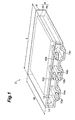
- Fig. 1 is a perspective view showing a lithium-ion secondary battery which is a preferred embodiment of the electrochemical device in accordance with the present invention
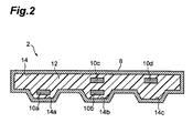
- Fig. 2 is a schematic end face view showing the lithium-ion secondary battery of Fig. 1 as seen from its opening part side
- Fig. 3 is a top plan view of a terminal member used in a method of manufacturing the lithium-ion secondary battery of Fig. 1
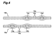
- Fig. 4 is a side view of terminal members (elemental devices) used in a method of manufacturing the lithium-ion secondary battery of Fig. 1
- Fig. 5 is a schematic end face view of a lithium-ion secondary battery which is another embodiment of the electrochemical device in accordance with the present invention as seen from the opening part side
- Fig. 5 is a schematic end face view of a lithium-ion secondary battery which is another embodiment of the electrochemical device in accordance with the present invention as seen from the opening part side
- Fig. 1 is a perspective view showing a lithium-ion secondary battery which
- Fig. 6 is a top plan view of a terminal member used in a conventional method of manufacturing a lithium-ion secondary battery
- Fig. 7 is a side view of terminal members (elemental devices) used in the conventional method of manufacturing a lithium-ion secondary battery
- Fig. 8 is a schematic end face view of the lithium-ion secondary battery made by the conventional method of manufacturing a lithium-ion secondary battery as seen from the opening part side.
- a lithium-ion secondary battery (hereinafter referred to as battery 2) which is a preferred embodiment of the present invention will be explained in detail with reference to the drawings.
- battery 2 a lithium-ion secondary battery
- the same or equivalent parts will be referred to with the same numerals or letters while omitting their overlapping explanations.
- Positional relationships such as those of upper, lower, left, and right are based on those shown in the drawings unless otherwise specified. Ratios of dimensions in the drawings are not limited to those depicted.
- a multilayer body 6 formed by laminating two electrode bodies 4a, 4b each having positive and negative electrodes laminated with a separator interposed therebetween are accommodated in an outer package 8 in the battery 2 in accordance with this embodiment.
- Figs. 1 and 2 omit the positive and negative electrodes and separators.
- the two electrode bodies 4a, 4b are laminated with a partition (not depicted) interposed therebetween.
- the partition is made of a material which is impermeable to respective electrolytic solutions contained in the two electrode bodies 4a, 4b. Providing the partition can keep the respective electrolytic solutions contained in the two electrode bodies 4a, 4b from mixing with each other and restrain the voltage of the battery 2 from decreasing.
- Planar leads 10a, 10b are electrically connected to the positive and negative electrodes in the electrode body 4a, respectively.
- Planar leads 10c, 10d are electrically connected to the positive and negative electrodes in the electrode body 4b, respectively.
- a sealing member 12 is in close contact with surroundings of the leads 10a to 10d, and is held by an opening part 14 of the outer package 8, so as to seal the opening part 14.
- the leads 10a to 10d extending from the multilayer body 6 project out of the outer package 8 at the opening part 14.
- lead takeout portions 14a, 14b, 14c Portions where the leads 10 extend from within the outer package 8 to the outside thereof through the sealing member 12 are referred to as lead takeout portions 14a, 14b, 14c.
- one surface of the outer package 8 is formed in a concavo-convex pattern, such as to form three lead takeout portions 14a, 14b, 14c.
- the other surface of the outer package 8, which is made flat, is placed on a reference surface when mounted to an electronic device. Since one surface of the outer package 8 is formed in a concavo-convex pattern, the sealing member 12 converges on the surroundings of the leads positioned at the lead takeout portions 14a, 14b, 14c when fusing the opening part 14 and sealing member 12 together, whereby the hermeticity of the opening part 14 improves.
- the two electrode bodies 4a, 4b are laminated such as to yield portions where different numbers of leads 10 overlap each other in the laminating direction of the electrode bodies 4a, 4b in the opening part 14. That is, one lead 10a is arranged at the lead takeout portion 14a on one end side of the opening portion 14, one lead 10d is arranged at the lead takeout portion 14c on the other end side, and two leads 10b, 10c overlapping each other in the laminating direction are arranged at the lead takeout portion 14b positioned at the center of the opening part 14. One of the two leads 10b, 10c positioned at the center of the lead takeout portion 14b is connected to the positive electrode, while the other is connected to the negative electrode.
- the two electrode bodies 4a, 4b can be connected in series, so as to improve the voltage of the battery 2.
- the thickness of the sealing member 12 from the surface of the outer package 8 to the surface of the lead 10 in the laminating direction of the electrode bodies 4a, 4b on one side (upper side) of the lead 10 differs from that on the other side (lower side) of the lead 10.
- the thickness of the sealing member 12 filling the upper gap between the lead 10a and the outer package 8 is greater than that of the sealing member 12 filling the lower gap between the lead 10a and the outer package 8.
- the thickness of the sealing member 12 filling the lower gap between the lead 10d and the outer package 8 is greater than that of the sealing member 12 filling the upper gap between the lead 10d and the outer package 8.
- the electrodes 10a, 10b connected to the electrode body 4a are arranged within the same plane perpendicular to the laminating direction of the electrode bodies 4a, 4b, while the leads 10c, 10d connected to the electrode body 4b are arranged within the same plane perpendicular to the laminating direction of the electrode bodies 4a, 4b.
- the thickness of the sealing member 12 from the surface of the outer package 8 to the surface of the lead 10a, 10d in the laminating direction of the electrode bodies 4a, 4b on one side of the leads 10a, 10d differs from that on the other side of the leads 10a, 10d such that the respective pairs of leads 10a, 10b connected to the electrode body 4a and leads 10c, 10d connected to the electrode body 4b are arranged on the same planes perpendicular to the laminating direction of the electrode bodies 4a, 4b, the total thickness of the sealing member 12 and lead 10 becomes substantially uniform in the laminating direction of the electrode bodies 4a, 4b at the lead takeout portions 14a, 14b, 14c. Therefore, the opening part 14 is completely filled with the sealing member 12 that is in close contact with the surroundings of the leads 10a to 10d, whereby distortions can be suppressed in the sealed opening part 14.
- Each of the positive electrodes in the electrode bodies 4a, 4b comprises a sheet-like positive electrode current collector and a positive electrode active material layer covering a surface of the positive electrode current collector which opposes the separator and negative electrode.
- Each of the negative electrodes in the electrode bodies 4a, 4b comprises a sheet-like negative electrode current collector and a negative electrode active material layer covering a surface of the negative electrode current collector which opposes the separator and positive electrode.
- Positive and negative electrode current collectors are current collectors used in known electrochemical devices, examples of which include copper, aluminum, nickel, and the like shaped into band-like forms.
- the positive electrode active material layer is a layer containing a positive electrode active material (cathode active material), a conductive auxiliary agent, a binder, and the like.
- the cathode active material is not restricted in particular as long as it allows occlusion and release of lithium ions, desorption and insertion of lithium ions (intercalation), or doping and undoping of lithium ions and counter anions of the lithium ions (such as PF 6 - ) to proceed reversibly; known electrode active materials can be used therefor.
- LiCoO 2 lithium cobaltate
- LiNiO 2
- the negative electrode active material layer is a layer containing a negative electrode active material (anode active material), a conductive auxiliary agent, a binder, and the like.
- the anode active material is not restricted in particular as long as it allows occlusion and release of lithium ions, desorption and insertion of lithium ions (intercalation), or doping and undoping of lithium ions and counter anions of the lithium ions (such as PF 6 - ) to proceed reversibly; known anode active materials can be used therefor.
- anode active material examples include carbon materials such as natural graphite, synthetic graphite, non-graphitizing carbon, graphitizable carbon, and low-temperature-firable carbon; metals such as Al, Si, and Sn which are combinable with lithium; amorphous compounds mainly composed of oxides such as SiO, SiO x , SiO 2 , and SnO 2 ; lithium titanate (Li 4 Ti 5 O 12 ); and TiO 2 .
- carbon materials More preferred are carbon materials having an interlayer distance d 002 of 0.335 to 0.338 nm and a crystallite size Lc 002 of 30 to 120 nm.
- Examples of carbon materials that satisfy such a condition include synthetic graphite, MCF (mesocarbon fiber), and MCMB (mesocarbon microbeads).
- the above-mentioned interlayer distance d 002 and crystallite size Lc 002 can be determined by X-ray diffraction.
- one formed from an electrically insulating porous body can be used, for example.
- the electrically insulating porous body include single-layer or multilayer films made of polyethylene, polypropylene, or a polyolefin, drawn films of resin mixtures, and fiber nonwoven cloth composed of at least one kind of constituent material selected from the group consisting of cellulose, polyester, and polypropylene.
- the positive and negative electrodes and separator contain an electrolytic solution (not depicted) therewithin.
- the electrolytic solution a nonaqueous electrolytic solution in which a lithium salt is dissolved in an organic solvent is used.
- the lithium salt include LiPF 6 , LiClO 4 , LiBF 4 , LiAsF 6 , LiCF 3 SO 3 , LiCF 3 CF 2 SO 3 , LiC(CF 3 SO 2 ) 3 , LiN(CF 3 SO 2 ) 2 , LiN(CF 3 CF 2 SO 2 ) 2 , LiN(CF 3 SO 2 )(C 4 F 9 SO 2 ), and LiN(CF 3 CF 2 CO) 2 .
- These salts may be used singly or in combinations of two or more species.
- the electrolytic solution may be gelled with polymers and the like added thereto.
- any solvent used in known batteries can be employed.
- single or mixed solvents of ring carbonates, linear carbonates, lactones, and esters can be used.
- Preferred specific examples include propylene carbonate, ethylene carbonate, and diethyl carbonate. They may be used singly, or two or more species may be used as a mixture in any proportions.
- any of metal cans constituted by aluminum or stainless steel and resin-film-coated metal foils of aluminum or stainless steel can be used.
- a material which adheres well to the opening part 14 at the time of fusing thereto is used.
- Specific examples include ethylene/vinyl acetate copolymers, ethylene/acrylate copolymers, and polypropylene polymers.
- the thickness of the positive or negative electrode current collector is about 5 to 50 ⁇ m.
- the thickness of the positive or negative electrode active material layer is about 1 to 200 ⁇ m.
- the thickness of the separator is about 5 to 50 ⁇ m.
- Each of the electrode bodies 4a, 4b has a thickness of about 0.25 to 5 mm.
- the thickness of the partition is about 10 to 100 ⁇ m.
- Each of the leads 10a to 10d has a thickness of about 50 to 1000 ⁇ m.
- the wall of the outer package 8 has a thickness of about 10 to 500 ⁇ m.
- the battery 2 has the maximum thickness of about 0.5 to 10 mm in the takeout portions 14a to 14c and a thickness of about 0.5 to 10 mm therebetween.
- the battery 2 has a longitudinal length L of about 10 to 50 mm in a direction perpendicular to the laminating direction of the electrode bodies 4a, 4b and a width W of about 10 to 50 mm.
- the method of manufacturing the battery 2 in accordance with this embodiment comprises an electrode body forming step, a terminal member forming step, an elemental device forming step, a multilayer body forming step, an accommodating step, and a sealing step.
- Electrode Body Forming Step laminates positive and negative electrodes with a separator interposed therebetween, so as to form electrode bodies 4a, 4b.
- the terminal member forming step holds a part of one or two planar leads 10 by a band-like sealing member 12 from both sides of the leads so as to form a terminal member 16 made of the one or two leads 10 and the sealing member 12.
- a terminal member 16a composed of one lead 10 and a sealing member 12a and a terminal member 16b composed of one lead 10 and a sealing member 12b as shown in Figs. 3 and 4 .
- the sealing members 12a, 12b represent respective parts of a sealing member 12c formed by integrating them.
- the terminal member 16a can be formed by holding a part of the lead 10 from both sides thereof with center parts of the band-like sealing members 12a.
- the terminal member 16b can be formed by holding a part of the lead 10 from both sides thereof with portions of the band-like sealing member 12b between their center and end parts.
- each of the sealing members 12a, 12b has a thickness of about 60 to 1200 ⁇ m.
- the terminal members 16a, 16b i.e., sealing members 12a, 12b
- a part of the terminal member 16b may be substituted by a member in which the terminal member 16a and the sealing member 12a alone are assembled without being integrated with each other.
- the length L1 of the sealing member 12a extending from the lead 10 to one side in the lateral direction equals the length L2 of the sealing member 12a extending from the lead 10 to the other side in the lateral direction.
- the length L3 of the sealing member 12a extending from the lead 10 to one side in the lateral direction is shorter than the length L4 of the sealing member 12a extending from the lead 10 to the other side in the lateral direction.
- the terminal member forming step uses the sealing member 12c having such a length as to hold a part of two leads 10 and extend to all of the lead takeout portions 14a, 14b, 14c in the opening part 14 of the outer package 8. That is, a terminal member 16c having a structure in which the terminal members 16a, 16b are integrated with each other is preferably formed by holding a part of two planar leads 10 from both sides thereof with the band-like sealing members 12c in which the sealing members 12a, 12b are integrated with each other.
- the method of manufacturing the battery 2 using the terminal member 16c will be explained.
- the elemental device forming step electrically connects respective leads 10 of the terminal member 16c to the positive and negative electrodes of the electrode body 4a, so as to form an elemental device 18a in which two leads 10a, 10b having the sealing members 12c attached thereto are connected to one electrode body 4a (not depicted) as shown in Fig. 4 .
- an elemental device 18b in which two leads 10c, 10d having the sealing members 12c attached thereto are connected to one electrode body 4b (not depicted) is formed.
- the multilayer forming step laminates two elemental devices 18a, 18b, which are formed by using the electrode bodies 4a, 4b, such as to yield portions where different numbers of leads 10 overlap each other in the laminating direction of the electrode bodies 4a, 4b in the opening part 14 of the outer package 8 (see Figs. 1 and 2 ), thereby forming a multilayer body composed of the elemental devices 18a, 18b (hereinafter referred to as multilayer body). That is, as shown in Fig.
- the elemental devices 18a, 18b are laminated in such a positional relationship that the leads 10b, 10c overlap each other in the laminating direction of the elemental devices 18a, 18b while the lead 10a of the elemental device 18a and the lead 10d of the elemental device 18b hold the leads 10b, 10c therebetween.
- One of the leads 10b, 10c is connected to the positive electrode, while the other is connected to the negative electrode.
- the number of laminations of the elemental devices 18a, 18b coincides with the number of units of the sealing members 12c.
- the total thickness of the sealing members 12c arranged on one side and the other side of the leads 10a to 10d in the laminating direction of the electrode bodies 4a, 4b can be made substantially the same in the multilayer body.
- the accommodating step accommodates the multilayer body in the outer package 8 such that the leads 10a to 10d and the sealing members 12c holding them in the multilayer body are arranged at the opening part 14 of the outer package 8.
- the sealing step fuses the sealing members 12c of the multilayer body and the opening part 14 together, so as to seal the opening part 14 in such a state that the leads 10a to 10d extend from the respective lead takeout parts 14a to 14c to the outside of the outer package 8.
- the sealing members 12c of the multilayer body and the opening part 14 are fused together while providing portions where the thickness of the sealing member 12c from the surface of the outer package 8 to the surface of the lead 10a to 10d in the laminating direction of the electrode bodies 4a, 4b on one side of the leads 10a to 10d differs from that on the other side of the leads 10a to 10d in the sealing step such that the two leads 10a, 10b connected to the electrode body 4a are arranged within the same plane perpendicular to the laminating direction of the electrode bodies 4a, 4b and the two leads 10c, 10d connected to the electrode body 4b are arranged within the same plane perpendicular to the laminating direction of the electrode bodies 4a, 4b after the sealing step. This yields the battery 2.
- the sealing step fuses the sealing members 12c of the multilayer body and the opening part 14 together such that the total thickness of the sealing members 12c (sealing member 12 in the battery 2) arranged on one side and the other side of the leads 10a to 10d in the laminating direction of the electrode bodies 4a, 4b is made substantially the same in all of the lead takeout portions 14a to 14c in the opening part 14.
- the effect of restraining distortions and gaps from being formed in the opening part 14 of the outer package 8 becomes remarkable.
- the total thickness of the sealing members 12c in parts corresponding to the lead takeout portions 14a to 14c before fusion is so small that none of distortions and gaps occurs in the opening part 14 of the resulting battery 2. More specifically, with respect to the total thickness of the sealing member 12 before fusion in a part corresponding to one lead takeout portion in the resulting battery 2, the total thickness of the sealing member 12 before fusion in a part corresponding to a lead takeout portion adjacent to the former lead takeout portion preferably falls within the range of 85 to 115%.
- the total thickness of the sealing member 12 and lead 10 in the lead takeout portion adjacent to the former lead takeout portion preferably falls within the range of 40 to 160%.
- the multilayer body forming step laminates two elemental devices 18a, 18b such as to yield portions where different numbers of leads 10 overlap each other in the laminating direction of the electrodes 4a, 4b (i.e., the laminating direction of the elemental devices 18a, 18b) in the opening part 14.
- portions where only one lead 10 is arranged as in the lead takeout portions 14a, 14c and a portion where two leads 10b, 10c overlap each other in the laminating direction as in the lead takeout portion 14b are generated.
- the leads 10b, 10c can electrically be connected to each other, so as to connect the electrode bodies 4a, 4b in series, thereby improving the voltage of the battery 2.
- this embodiment completely fills the opening part 14 with the sealing member 12 that is in close contact with the surroundings of the leads 10a to 10d in the resulting battery 2, and thus can suppress distortions in the opening part 14.
- the terminal members 16c formed by using the sealing members 12c having such a length as to extend to all the lead takeout portions 14a, 14b, 14c in the opening part 14 of the outer package 8 are laminated on each other as a part of the elemental devices 18a, 18b in the multilayer body forming step, whereby the total thickness of the sealing members 12c arranged on one side and the other side of the lead 10 in the laminating direction of the electrode bodies 4a, 4b can easily be made substantially the same in all the lead takeout portions 14a, 14b, 14c in the sealing step.
- Using one terminal member 16c composed of two leads 10 and a pair of sealing members 12c holding them makes it easier to form the elemental devices 18a, 18b than in the case using the terminal members 16a, 16b each combining one lead with a sealing member.
- terminal members 16d each formed by using a sealing member 12d which is not long enough to reach all the lead takeout portions 14a, 14b, 14c in the opening part 14 of the outer package 8 as shown in Fig. 6 are laminated such as to yield portions where different numbers of leads 10 overlap each other in the laminating direction as shown in Fig. 7 as in a conventional case, the total thickness of the sealing members 12d arranged on one side and the other side of the lead 10 in the laminating direction becomes uneven.
- the present invention is not limited to the above-mentioned embodiments.
- the electrochemical device is the battery 2 (lithium-ion secondary battery)
- the electrochemical device of the present invention is not limited thereto but may be any of secondary batteries other than the lithium-ion secondary battery, e.g., metal lithium secondary batteries, lithium capacitors, electric double-layer capacitors, and the like.
- electrode active materials suitable for the electrochemical devices may be used.
- acetylene black, graphite, activated carbon, and the like are used as active materials contained in the cathode and anode active material containing layers.
- electrolytic solution for use include solutions of quaternary ammonium salts such as tetraethylammonium tetrafluoroborate in organic solvents such as propylene carbonate, diethylene carbonate, and acetonitrile.
- the electrochemical device of the present invention is also usable for a power supply for a self-propelled micromachine, an IC card, or the like and a dispersed power supply located on or in a printed circuit board.
- Both sides of the opening part 14 of the outer package 8 may be formed in a concavo-convex pattern as shown in Fig. 5 .
- the number of electrode bodies constituting the multilayer body 6 may be 3 or more.
- the battery 2 comprises an outer package 8 accommodating a multilayer body 6 formed by laminating two electrode bodies 4a, 4b each having positive and negative electrodes laminated with a separator interposed therebetween, planar leads 10a to 10d respectively connected to the positive and negative electrodes while extending from the multilayer body 6 to the outside of the outer package 8, and a sealing member 12 in close contact with the surroundings of the leads 10a to 10d and held by the opening part 14 of the outer package 8 so as to seal the opening part 14.
- One lead 10a is arranged at the lead takeout portion 14a on one end side of the opening part 14, one lead 10d is arranged at the lead takeout portion 14c on the other end side, and two leads 10b, 10c overlapping each other in the laminating direction are arranged at the lead takeout portion 14b positioned at the center of the opening part 14.
- the thickness of the sealing member 12 filling the upper gap between the lead 10a and the outer package 8 is greater than the thickness of the sealing member 12 filling the lower gap between the lead 10a and the outer package 8.
- the thickness of the sealing member 12 filling the lower gap between the lead 10d and the outer package 8 is greater than the thickness of the sealing member 12 filling the upper gap between the lead 10d and the outer package 8.
- the leads 10a, 10b connected to the electrode body 4a are arranged within the same plane perpendicular to the laminating direction of the electrode bodies 4a, 4b, while the leads 10c, 10d connected to the electrode body 4b are arranged within the same plane perpendicular to the laminating direction of the electrode bodies 4a, 4b.
- the above-mentioned lithium-ion secondary battery was made by a manufacturing method comprising an electrode body forming step, a terminal member forming step, an elemental device forming step, a multilayer body forming step, an accommodating step, and a sealing step as shown in the following.
- the aluminum foil formed with the active material layers was cut into a size of 14 mm ⁇ 10 mm, so as to yield a positive electrode.
- an uncoated part exposing the aluminum foil was formed by a length of 4 mm from a longitudinal end part on both sides of thus cut positive electrode.
- a coating material formed by dispersing a mixture of graphite, PVdF, and acetylene black at a volume ratio of 75:15:10 into NMP was applied to both sides of a copper foil having a thickness of 0.02 mm, and then NMP was removed, so as to form active material layers.
- the total thickness of the copper foil and active material layers was 0.10 mm.
- the copper foil formed with the active material layers was cut into a size of 14 mm ⁇ 10 mm, so as to yield a negative electrode.
- an uncoated part exposing the copper foil was formed by a length of 4 mm from a longitudinal end part on both sides of thus cut negative electrode.
- Terminal Member Forming Step a part of the two planar leads 10a, 10b were held with band-like sealing members 12c from both sides of the leads 10, so as to form a terminal member 16c composed of two leads 10a, 10b and the sealing members 12c as shown in Figs. 3 and 4 .
- a terminal member 16c composed of two leads 10c, 10d and the sealing members 12c was formed.
- portions where only the sealing members 12c existed without any lead were formed on the opposite sides of the leads 10b, 10c at the longitudinal center parts of the sealing members 12c from the leads 10a, 10d on the end part sides, respectively.
- each of the leads 10a to 10d a nickel foil having a size of 2 mm in width ⁇ 10 mm in length ⁇ 0.03 mm in thickness was used.
- As the sealing member 12c a polyolefin sheet having a size of 3 mm in width ⁇ 11 mm in length was used. The length of 11 mm in the polyolefin sheet was made identical to the longitudinal length 11 mm in the opening part 14 of the outer package 8.
- the terminal members 16c were formed by using the sealing members 12c each having such a length as to hold a part of the two leads 10 and extend to all the lead takeout portions 14a, 14b, 14c in the opening part 14 of the outer package 8.
- Elemental Device Forming Step In the elemental device forming step, the lead 10a of the terminal member 16c was ultrasonically welded to an end portion of the uncoated part in the negative electrode of the electrode body 4a, while the lead 10b of the terminal member 16c was ultrasonically welded to the center of the uncoated part in the positive electrode of the electrode body 4a, whereby an elemental device 18a in which two leads 10a, 10b having the sealing members 12c attached thereto were connected to one electrode body 4a (not depicted) was formed as shown in Fig. 4 .
- the lead 10c of the terminal member 16c was ultrasonically welded to the center of the uncoated part in the negative electrode of the electrode body 4b, while the lead 10d of the terminal member 16c was ultrasonically welded to an end portion of the uncoated part in the positive electrode of the electrode body 4b, whereby an elemental device 18b in which two leads 10c, 10d having the sealing members 12c attached thereto were connected to one electrode body 4b (not depicted) was formed.
- Multilayer Body Forming Step In the multilayer body forming step, the elemental devices 18a, 18b were laminated with a polyimide sheet having a thickness of 0.03 mm interposed therebetween, so as to form a multilayer body as shown in Fig. 4 .
- the elemental devices 18a, 18b were laminated in such a positional relationship that the leads 10b, 10c overlapped each other in the laminating direction of the elemental devices 18a, 18b while the lead 10a of the elemental device 18a and the lead 10d of the elemental device 18b held the leads 10b, 10c therebetween, whereby the total thickness of the sealing members 12c arranged on one side and the other side of the leads 10a to 10d in the laminating direction of the electrode bodies 4a, 4b was made substantially the same.
- the leads 10b, 10c of thus obtained multilayer body were ultrasonically welded to each other.
- the multilayer body was accommodated in the outer package 8 made of an aluminum laminate such that the leads 10a to 10d and the sealing members 12c holding them in the multilayer body were arranged in the opening part 14 of the outer package 8. Further, an electrolytic solution formed by adding 3 wt% of LiPF 6 to a mixed solvent of propylene carbonate and ethylene carbonate was injected into the outer package 8.
- sealing step the sealing members 12c arranged throughout the opening part 14 of the outer package 8 as shown in Figs. 1 and 2 were heated, so as to seal the opening part 14, thereby yielding the lithium-ion secondary battery of Example.
- the sealing members 12c of the multilayer body and the opening part 14 were fused together such that the total thickness of the sealing members 12c (sealing member 12 in the battery) arranged on one side and the other side of the leads 10a to 10d in the laminating direction of the electrode bodies 4a, 4b was made substantially the same in all the lead takeout portions 14a to 14c in the opening part 12.
- the leads 10a, 10b connected to the electrode body 4a were arranged within the same plane perpendicular to the laminating direction of the electrode bodies 4a, 4b, while the leads 10c, 10d connected to the electrode body 4b were arranged within the same plane perpendicular to the laminating direction of the electrode bodies 4a, 4b.
- Comparative Example In Comparative Example, a polyolefin sheet having a size of 3 mm in width ⁇ 7.5 mm in length was used as a sealing member. That is, as shown in Figs. 6 and 7 , Comparative Example employed a sealing member 12d which was not long enough to reach all of the lead takeout portions 14a, 14b, 14c in the opening part 14 of the outer package 8, so as to form a terminal member 16d.
- the electrode bodies 4a, 4b having thus formed terminal members 16d were laminated such as to yield portions where different numbers of leads 10 overlapped each other in the laminating direction as shown in Fig. 7 , whereby a multilayer body was formed. Except for using the terminal members 16d as such, the lithium-ion secondary battery of Comparative Example was made as in Example.
- the lithium-ion secondary batteries of Example and Comparative Examples were made by 100 each, and the impedance of each lithium-ion secondary battery was measured.
- the minimum and maximum values were 96 [m ⁇ ] and 100 [m ⁇ ], respectively.
- the impedance values of 100 lithium-ion secondary batteries of Comparative Example on the other hand, the minimum value was 128.6 [m ⁇ ], while the maximum value diverged at infinity.
Landscapes
- Engineering & Computer Science (AREA)
- Power Engineering (AREA)
- Microelectronics & Electronic Packaging (AREA)
- Chemical & Material Sciences (AREA)
- Chemical Kinetics & Catalysis (AREA)
- Electrochemistry (AREA)
- General Chemical & Material Sciences (AREA)
- Manufacturing & Machinery (AREA)
- Secondary Cells (AREA)
- Connection Of Batteries Or Terminals (AREA)
- Sealing Battery Cases Or Jackets (AREA)
- Electric Double-Layer Capacitors Or The Like (AREA)
Applications Claiming Priority (1)
| Application Number | Priority Date | Filing Date | Title |
|---|---|---|---|
| JP2007340273A JP4725578B2 (ja) | 2007-12-28 | 2007-12-28 | 電気化学デバイス、及び電気化学デバイスの製造方法 |
Publications (3)
| Publication Number | Publication Date |
|---|---|
| EP2075808A2 true EP2075808A2 (fr) | 2009-07-01 |
| EP2075808A3 EP2075808A3 (fr) | 2010-10-20 |
| EP2075808B1 EP2075808B1 (fr) | 2013-07-24 |
Family
ID=40472312
Family Applications (1)
| Application Number | Title | Priority Date | Filing Date |
|---|---|---|---|
| EP08021560.1A Active EP2075808B1 (fr) | 2007-12-28 | 2008-12-11 | Dispositif électrochimique et procédé de fabrication de dispositif électrochimique |
Country Status (4)
| Country | Link |
|---|---|
| US (2) | US7785738B2 (fr) |
| EP (1) | EP2075808B1 (fr) |
| JP (1) | JP4725578B2 (fr) |
| CN (1) | CN101471450B (fr) |
Cited By (1)
| Publication number | Priority date | Publication date | Assignee | Title |
|---|---|---|---|---|
| EP2822055A4 (fr) * | 2012-02-29 | 2015-10-21 | Nisshin Steel Co Ltd | Matériau externe pour batterie stratifiée, procédé pour fabriquer un matériau externe pour batterie stratifiée, procédé pour fabriquer une batterie stratifiée et batterie stratifiée |
Families Citing this family (8)
| Publication number | Priority date | Publication date | Assignee | Title |
|---|---|---|---|---|
| CN103840151B (zh) * | 2013-12-13 | 2016-04-13 | 山东海特电子新材料有限公司 | 一种特殊单晶结构的三元正极材料及其制备方法 |
| CN105655532A (zh) * | 2014-11-10 | 2016-06-08 | 宁德时代新能源科技股份有限公司 | 电池组及其堆叠方法 |
| MY195773A (en) | 2016-05-20 | 2023-02-11 | Kyocera Avx Components Corp | Multi-Cell Ultracapacitor |
| US11830672B2 (en) | 2016-11-23 | 2023-11-28 | KYOCERA AVX Components Corporation | Ultracapacitor for use in a solder reflow process |
| JP7818581B2 (ja) * | 2020-09-08 | 2026-02-20 | 寧徳新能源科技有限公司 | 電気化学装置及び電子装置 |
| CN112002868B (zh) * | 2020-09-08 | 2021-07-20 | 宁德新能源科技有限公司 | 一种电化学装置及电子装置 |
| CN112467263B (zh) * | 2020-09-29 | 2023-03-31 | 昆山兴能能源科技有限公司 | 一种塑料型电池及其生产方法 |
| CN114824593B (zh) * | 2022-05-25 | 2024-05-17 | 东莞新能德科技有限公司 | 电化学装置以及用电设备 |
Citations (1)
| Publication number | Priority date | Publication date | Assignee | Title |
|---|---|---|---|---|
| JPH11329382A (ja) | 1998-05-21 | 1999-11-30 | Furukawa Electric Co Ltd:The | フィルム状電池 |
Family Cites Families (11)
| Publication number | Priority date | Publication date | Assignee | Title |
|---|---|---|---|---|
| JPH04248254A (ja) * | 1991-01-24 | 1992-09-03 | Shin Kobe Electric Mach Co Ltd | 密閉形鉛蓄電池および密閉形鉛蓄電池の接続法 |
| JP2003162996A (ja) * | 2001-11-26 | 2003-06-06 | Sumitomo Electric Ind Ltd | 電力貯蔵デバイスおよびこれに用いられるリードユニット |
| JP2004087238A (ja) * | 2002-08-26 | 2004-03-18 | Nissan Motor Co Ltd | 積層型電池 |
| JP3695435B2 (ja) * | 2002-09-03 | 2005-09-14 | 日産自動車株式会社 | ラミネート外装扁平型電池 |
| JP3866740B2 (ja) * | 2003-09-26 | 2007-01-10 | 株式会社東芝 | 非水電解質二次電池、組電池及び電池パック |
| JP4089581B2 (ja) * | 2003-09-29 | 2008-05-28 | 新神戸電機株式会社 | 積層電池 |
| JP4961673B2 (ja) * | 2005-03-08 | 2012-06-27 | 住友電気工業株式会社 | 非水電解質電池用タブリードの製造方法 |
| JP2006309993A (ja) * | 2005-04-27 | 2006-11-09 | Gs Yuasa Corporation:Kk | 電池及び組電池 |
| JP4661648B2 (ja) * | 2005-06-16 | 2011-03-30 | 日産自動車株式会社 | 扁平型電池および該扁平型電池を用いた組電池 |
| CN100444430C (zh) * | 2005-06-16 | 2008-12-17 | 日产自动车株式会社 | 扁平型电池及采用该扁平型电池的电池组 |
| WO2007112116A2 (fr) * | 2006-03-27 | 2007-10-04 | Alcoa Inc. | Connexion de modules intégrés pour batterie vhe |
-
2007
- 2007-12-28 JP JP2007340273A patent/JP4725578B2/ja not_active Expired - Fee Related
-
2008
- 2008-12-11 EP EP08021560.1A patent/EP2075808B1/fr active Active
- 2008-12-18 US US12/338,429 patent/US7785738B2/en active Active
- 2008-12-26 CN CN2008101888344A patent/CN101471450B/zh active Active
-
2010
- 2010-07-23 US US12/842,357 patent/US7855013B2/en active Active
Patent Citations (1)
| Publication number | Priority date | Publication date | Assignee | Title |
|---|---|---|---|---|
| JPH11329382A (ja) | 1998-05-21 | 1999-11-30 | Furukawa Electric Co Ltd:The | フィルム状電池 |
Cited By (1)
| Publication number | Priority date | Publication date | Assignee | Title |
|---|---|---|---|---|
| EP2822055A4 (fr) * | 2012-02-29 | 2015-10-21 | Nisshin Steel Co Ltd | Matériau externe pour batterie stratifiée, procédé pour fabriquer un matériau externe pour batterie stratifiée, procédé pour fabriquer une batterie stratifiée et batterie stratifiée |
Also Published As
| Publication number | Publication date |
|---|---|
| JP4725578B2 (ja) | 2011-07-13 |
| EP2075808B1 (fr) | 2013-07-24 |
| EP2075808A3 (fr) | 2010-10-20 |
| US20100284127A1 (en) | 2010-11-11 |
| CN101471450A (zh) | 2009-07-01 |
| US20090214945A1 (en) | 2009-08-27 |
| CN101471450B (zh) | 2011-07-06 |
| US7855013B2 (en) | 2010-12-21 |
| JP2009163928A (ja) | 2009-07-23 |
| US7785738B2 (en) | 2010-08-31 |
Similar Documents
| Publication | Publication Date | Title |
|---|---|---|
| US8481198B2 (en) | Wound electrochemical device and method of manufacturing same | |
| US7855013B2 (en) | Electric double-layer capacitor and method of manufacturing electric double-layer capacitor | |
| US7820337B2 (en) | Electrochemical device | |
| JP6504158B2 (ja) | 積層型電池及びその製造方法 | |
| JP5157244B2 (ja) | 電気化学デバイス及びその製造方法 | |
| US8247100B2 (en) | Electrochemical device | |
| CN107863495B (zh) | 电极结构体、二次电池、电池包及车辆 | |
| JP4293501B2 (ja) | 電気化学デバイス | |
| US9614194B2 (en) | Battery | |
| EP2075869B1 (fr) | Dispositif électrochimique enroulé et son procédé de fabrication | |
| JP4557001B2 (ja) | 電気化学デバイス用電極及び電気化学デバイス | |
| US20110244304A1 (en) | Stack type battery | |
| US20180090794A1 (en) | Secondary battery | |
| JP2002298825A (ja) | 電気化学デバイスの製造方法、および電気化学デバイス | |
| JP5622692B2 (ja) | 非水電解質電池及び電池パック | |
| US8192875B2 (en) | Method of manufacturing lithium-ion secondary battery, electrolytic solution, and lithium-ion secondary battery | |
| JP2022056148A (ja) | 二次電池 | |
| US20250293316A1 (en) | Nonaqueous electrolyte battery and battery pack | |
| JP4609353B2 (ja) | 充電システム | |
| US20050237031A1 (en) | Power supply, charging apparatus, and charging system | |
| WO2026078742A1 (fr) | Groupe d'électrodes, batterie et bloc-batterie |
Legal Events
| Date | Code | Title | Description |
|---|---|---|---|
| PUAI | Public reference made under article 153(3) epc to a published international application that has entered the european phase |
Free format text: ORIGINAL CODE: 0009012 |
|
| 17P | Request for examination filed |
Effective date: 20081211 |
|
| AK | Designated contracting states |
Kind code of ref document: A2 Designated state(s): AT BE BG CH CY CZ DE DK EE ES FI FR GB GR HR HU IE IS IT LI LT LU LV MC MT NL NO PL PT RO SE SI SK TR |
|
| AX | Request for extension of the european patent |
Extension state: AL BA MK RS |
|
| PUAL | Search report despatched |
Free format text: ORIGINAL CODE: 0009013 |
|
| AK | Designated contracting states |
Kind code of ref document: A3 Designated state(s): AT BE BG CH CY CZ DE DK EE ES FI FR GB GR HR HU IE IS IT LI LT LU LV MC MT NL NO PL PT RO SE SI SK TR |
|
| AX | Request for extension of the european patent |
Extension state: AL BA MK RS |
|
| AKX | Designation fees paid |
Designated state(s): DE FR GB |
|
| REG | Reference to a national code |
Ref country code: DE Ref legal event code: R079 Ref document number: 602008026194 Country of ref document: DE Free format text: PREVIOUS MAIN CLASS: H01G0009100000 Ipc: H01M0002020000 |
|
| GRAP | Despatch of communication of intention to grant a patent |
Free format text: ORIGINAL CODE: EPIDOSNIGR1 |
|
| RIC1 | Information provided on ipc code assigned before grant |
Ipc: H01G 11/74 20130101ALI20130201BHEP Ipc: H01G 9/10 20060101ALI20130201BHEP Ipc: H01M 2/06 20060101ALI20130201BHEP Ipc: H01G 11/84 20130101ALI20130201BHEP Ipc: H01G 11/80 20130101ALI20130201BHEP Ipc: H01M 2/02 20060101AFI20130201BHEP |
|
| GRAS | Grant fee paid |
Free format text: ORIGINAL CODE: EPIDOSNIGR3 |
|
| GRAA | (expected) grant |
Free format text: ORIGINAL CODE: 0009210 |
|
| AK | Designated contracting states |
Kind code of ref document: B1 Designated state(s): DE FR GB |
|
| REG | Reference to a national code |
Ref country code: GB Ref legal event code: FG4D |
|
| REG | Reference to a national code |
Ref country code: DE Ref legal event code: R096 Ref document number: 602008026194 Country of ref document: DE Effective date: 20130919 |
|
| PLBE | No opposition filed within time limit |
Free format text: ORIGINAL CODE: 0009261 |
|
| STAA | Information on the status of an ep patent application or granted ep patent |
Free format text: STATUS: NO OPPOSITION FILED WITHIN TIME LIMIT |
|
| 26N | No opposition filed |
Effective date: 20140425 |
|
| REG | Reference to a national code |
Ref country code: DE Ref legal event code: R097 Ref document number: 602008026194 Country of ref document: DE Effective date: 20140425 |
|
| GBPC | Gb: european patent ceased through non-payment of renewal fee |
Effective date: 20131211 |
|
| REG | Reference to a national code |
Ref country code: FR Ref legal event code: ST Effective date: 20140829 |
|
| PG25 | Lapsed in a contracting state [announced via postgrant information from national office to epo] |
Ref country code: FR Free format text: LAPSE BECAUSE OF NON-PAYMENT OF DUE FEES Effective date: 20131231 Ref country code: GB Free format text: LAPSE BECAUSE OF NON-PAYMENT OF DUE FEES Effective date: 20131211 |
|
| REG | Reference to a national code |
Ref country code: DE Ref legal event code: R079 Ref document number: 602008026194 Country of ref document: DE Free format text: PREVIOUS MAIN CLASS: H01M0002020000 Ipc: H01M0050100000 |
|
| PGFP | Annual fee paid to national office [announced via postgrant information from national office to epo] |
Ref country code: DE Payment date: 20241029 Year of fee payment: 17 |