EP2075893A2 - Unterseitenbasierter Ausgleich in einem Lithiumionenbatteriesystem - Google Patents
Unterseitenbasierter Ausgleich in einem Lithiumionenbatteriesystem Download PDFInfo
- Publication number
- EP2075893A2 EP2075893A2 EP20080166598 EP08166598A EP2075893A2 EP 2075893 A2 EP2075893 A2 EP 2075893A2 EP 20080166598 EP20080166598 EP 20080166598 EP 08166598 A EP08166598 A EP 08166598A EP 2075893 A2 EP2075893 A2 EP 2075893A2
- Authority
- EP
- European Patent Office
- Prior art keywords
- cells
- cell
- voltage
- discharging
- charging
- Prior art date
- Legal status (The legal status is an assumption and is not a legal conclusion. Google has not performed a legal analysis and makes no representation as to the accuracy of the status listed.)
- Granted
Links
Images


Classifications
-
- H—ELECTRICITY
- H02—GENERATION; CONVERSION OR DISTRIBUTION OF ELECTRIC POWER
- H02J—ELECTRIC POWER NETWORKS; CIRCUIT ARRANGEMENTS OR SYSTEMS FOR SUPPLYING OR DISTRIBUTING ELECTRIC POWER; SYSTEMS FOR STORING ELECTRIC ENERGY
- H02J7/00—Circuit arrangements for charging or discharging batteries or for supplying loads from batteries
- H02J7/50—Circuit arrangements for charging or discharging batteries or for supplying loads from batteries acting upon multiple batteries simultaneously or sequentially
- H02J7/52—Circuit arrangements for charging or discharging batteries or for supplying loads from batteries acting upon multiple batteries simultaneously or sequentially for charge balancing, e.g. equalisation of charge between batteries
- H02J7/54—Passive balancing, e.g. using resistors or parallel MOSFETs
-
- B—PERFORMING OPERATIONS; TRANSPORTING
- B60—VEHICLES IN GENERAL
- B60L—PROPULSION OF ELECTRICALLY-PROPELLED VEHICLES; SUPPLYING ELECTRIC POWER FOR AUXILIARY EQUIPMENT OF ELECTRICALLY-PROPELLED VEHICLES; ELECTRODYNAMIC BRAKE SYSTEMS FOR VEHICLES IN GENERAL; MAGNETIC SUSPENSION OR LEVITATION FOR VEHICLES; MONITORING OPERATING VARIABLES OF ELECTRICALLY-PROPELLED VEHICLES; ELECTRIC SAFETY DEVICES FOR ELECTRICALLY-PROPELLED VEHICLES
- B60L58/00—Methods or circuit arrangements for monitoring or controlling batteries or fuel cells, specially adapted for electric vehicles
- B60L58/10—Methods or circuit arrangements for monitoring or controlling batteries or fuel cells, specially adapted for electric vehicles for monitoring or controlling batteries
- B60L58/12—Methods or circuit arrangements for monitoring or controlling batteries or fuel cells, specially adapted for electric vehicles for monitoring or controlling batteries responding to state of charge [SoC]
- B60L58/15—Preventing overcharging
-
- H—ELECTRICITY
- H01—ELECTRIC ELEMENTS
- H01M—PROCESSES OR MEANS, e.g. BATTERIES, FOR THE DIRECT CONVERSION OF CHEMICAL ENERGY INTO ELECTRICAL ENERGY
- H01M10/00—Secondary cells; Manufacture thereof
- H01M10/42—Methods or arrangements for servicing or maintenance of secondary cells or secondary half-cells
- H01M10/44—Methods for charging or discharging
- H01M10/441—Methods for charging or discharging for several batteries or cells simultaneously or sequentially
-
- H—ELECTRICITY
- H01—ELECTRIC ELEMENTS
- H01M—PROCESSES OR MEANS, e.g. BATTERIES, FOR THE DIRECT CONVERSION OF CHEMICAL ENERGY INTO ELECTRICAL ENERGY
- H01M10/00—Secondary cells; Manufacture thereof
- H01M10/42—Methods or arrangements for servicing or maintenance of secondary cells or secondary half-cells
- H01M10/48—Accumulators combined with arrangements for measuring, testing or indicating the condition of cells, e.g. the level or density of the electrolyte
- H01M10/482—Accumulators combined with arrangements for measuring, testing or indicating the condition of cells, e.g. the level or density of the electrolyte for several batteries or cells simultaneously or sequentially
-
- H—ELECTRICITY
- H01—ELECTRIC ELEMENTS
- H01M—PROCESSES OR MEANS, e.g. BATTERIES, FOR THE DIRECT CONVERSION OF CHEMICAL ENERGY INTO ELECTRICAL ENERGY
- H01M50/00—Constructional details or processes of manufacture of the non-active parts of electrochemical cells other than fuel cells, e.g. hybrid cells
- H01M50/50—Current conducting connections for cells or batteries
- H01M50/543—Terminals
-
- H—ELECTRICITY
- H02—GENERATION; CONVERSION OR DISTRIBUTION OF ELECTRIC POWER
- H02J—ELECTRIC POWER NETWORKS; CIRCUIT ARRANGEMENTS OR SYSTEMS FOR SUPPLYING OR DISTRIBUTING ELECTRIC POWER; SYSTEMS FOR STORING ELECTRIC ENERGY
- H02J7/00—Circuit arrangements for charging or discharging batteries or for supplying loads from batteries
- H02J7/70—Circuit arrangements for charging or discharging batteries or for supplying loads from batteries characterised by the mechanical construction
- H02J7/751—Circuit arrangements for charging or discharging batteries or for supplying loads from batteries characterised by the mechanical construction concerning the insertion or the connection of the batteries
-
- H—ELECTRICITY
- H01—ELECTRIC ELEMENTS
- H01M—PROCESSES OR MEANS, e.g. BATTERIES, FOR THE DIRECT CONVERSION OF CHEMICAL ENERGY INTO ELECTRICAL ENERGY
- H01M10/00—Secondary cells; Manufacture thereof
- H01M10/05—Accumulators with non-aqueous electrolyte
- H01M10/052—Li-accumulators
- H01M10/0525—Rocking-chair batteries, i.e. batteries with lithium insertion or intercalation in both electrodes; Lithium-ion batteries
-
- H—ELECTRICITY
- H01—ELECTRIC ELEMENTS
- H01M—PROCESSES OR MEANS, e.g. BATTERIES, FOR THE DIRECT CONVERSION OF CHEMICAL ENERGY INTO ELECTRICAL ENERGY
- H01M10/00—Secondary cells; Manufacture thereof
- H01M10/42—Methods or arrangements for servicing or maintenance of secondary cells or secondary half-cells
- H01M10/425—Structural combination with electronic components, e.g. electronic circuits integrated to the outside of the casing
- H01M2010/4271—Battery management systems including electronic circuits, e.g. control of current or voltage to keep battery in healthy state, cell balancing
-
- H—ELECTRICITY
- H01—ELECTRIC ELEMENTS
- H01M—PROCESSES OR MEANS, e.g. BATTERIES, FOR THE DIRECT CONVERSION OF CHEMICAL ENERGY INTO ELECTRICAL ENERGY
- H01M2200/00—Safety devices for primary or secondary batteries
-
- H—ELECTRICITY
- H01—ELECTRIC ELEMENTS
- H01M—PROCESSES OR MEANS, e.g. BATTERIES, FOR THE DIRECT CONVERSION OF CHEMICAL ENERGY INTO ELECTRICAL ENERGY
- H01M2220/00—Batteries for particular applications
- H01M2220/30—Batteries in portable systems, e.g. mobile phone, laptop
-
- H—ELECTRICITY
- H01—ELECTRIC ELEMENTS
- H01M—PROCESSES OR MEANS, e.g. BATTERIES, FOR THE DIRECT CONVERSION OF CHEMICAL ENERGY INTO ELECTRICAL ENERGY
- H01M50/00—Constructional details or processes of manufacture of the non-active parts of electrochemical cells other than fuel cells, e.g. hybrid cells
- H01M50/50—Current conducting connections for cells or batteries
- H01M50/572—Means for preventing undesired use or discharge
- H01M50/574—Devices or arrangements for the interruption of current
-
- Y—GENERAL TAGGING OF NEW TECHNOLOGICAL DEVELOPMENTS; GENERAL TAGGING OF CROSS-SECTIONAL TECHNOLOGIES SPANNING OVER SEVERAL SECTIONS OF THE IPC; TECHNICAL SUBJECTS COVERED BY FORMER USPC CROSS-REFERENCE ART COLLECTIONS [XRACs] AND DIGESTS
- Y02—TECHNOLOGIES OR APPLICATIONS FOR MITIGATION OR ADAPTATION AGAINST CLIMATE CHANGE
- Y02E—REDUCTION OF GREENHOUSE GAS [GHG] EMISSIONS, RELATED TO ENERGY GENERATION, TRANSMISSION OR DISTRIBUTION
- Y02E60/00—Enabling technologies; Technologies with a potential or indirect contribution to GHG emissions mitigation
- Y02E60/10—Energy storage using batteries
-
- Y—GENERAL TAGGING OF NEW TECHNOLOGICAL DEVELOPMENTS; GENERAL TAGGING OF CROSS-SECTIONAL TECHNOLOGIES SPANNING OVER SEVERAL SECTIONS OF THE IPC; TECHNICAL SUBJECTS COVERED BY FORMER USPC CROSS-REFERENCE ART COLLECTIONS [XRACs] AND DIGESTS
- Y02—TECHNOLOGIES OR APPLICATIONS FOR MITIGATION OR ADAPTATION AGAINST CLIMATE CHANGE
- Y02P—CLIMATE CHANGE MITIGATION TECHNOLOGIES IN THE PRODUCTION OR PROCESSING OF GOODS
- Y02P70/00—Climate change mitigation technologies in the production process for final industrial or consumer products
- Y02P70/50—Manufacturing or production processes characterised by the final manufactured product
-
- Y—GENERAL TAGGING OF NEW TECHNOLOGICAL DEVELOPMENTS; GENERAL TAGGING OF CROSS-SECTIONAL TECHNOLOGIES SPANNING OVER SEVERAL SECTIONS OF THE IPC; TECHNICAL SUBJECTS COVERED BY FORMER USPC CROSS-REFERENCE ART COLLECTIONS [XRACs] AND DIGESTS
- Y02—TECHNOLOGIES OR APPLICATIONS FOR MITIGATION OR ADAPTATION AGAINST CLIMATE CHANGE
- Y02T—CLIMATE CHANGE MITIGATION TECHNOLOGIES RELATED TO TRANSPORTATION
- Y02T10/00—Road transport of goods or passengers
- Y02T10/60—Other road transportation technologies with climate change mitigation effect
- Y02T10/70—Energy storage systems for electromobility, e.g. batteries
Definitions
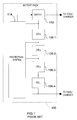
- the battery pack 100 includes multiple cells 106-1, 106-2, 106-3, and 106-4, each having a positive and a negative terminal.
- the cells 106 are connected in series, with the positive terminal of one cell 106 connected to the negative terminal of the next cell 106.
- the cells 106 may be lithium ion (Lilon) charge storage cells.
- the cells 106 may have varying charge storage capacities.
- the cells 106 with lower charge storage capacities will decrease in voltage faster than the cells 106 with larger storage capacities.
- the protection system 114 measures the voltages of the cells 106 and instructs the switch 110 to stop conducting when the voltage of one of the cells becomes too low.
- the switch 110 may stop conducting if the current flowing through it exceeds a safe operating level.
- FIG. 3 a graphical depiction of battery discharging according to the prior art is presented.
- the voltages of the cells decrease.
- the first three cells have 0.1 Ah remaining, and may be at a voltage of approximately 2.5 V.
- the fourth cell has zero capacity remaining, and may be at a lower voltage, such as 1.8 V, or even a negative voltage.
- Battery cells, and especially Lilon cells may be permanently damaged, and may even become unstable, when driven to low or negative voltages.
- the voltage of the fourth cell may be too low after 1.0 Ah has been drawn from the battery pack.
- the protection system 114 of FIG. 1 monitors the voltage of each of the cells. Without this monitoring, the user may continue using the battery pack even as one or more of the cells 106 runs out of capacity. As current is drawn from the first three cells, the fourth cell may even be driven to a negative voltage, which is likely detrimental to the fourth cell.
- the protection system 114 can prevent this from happening, but is expensive and complicated to include in each battery pack.
- a method comprises discharging each of a plurality of cells of a battery pack, stopping the discharging of a selected cell of the plurality of cells when the selected cell reaches a predetermined capacity, and charging the plurality of cells after the discharging has stopped for all of the plurality of cells.
- a battery charger comprises a discharging device, a charging device, and a control module.
- the discharging device discharges each of a plurality of cells of a battery pack.
- the charging device charges the plurality of cells.
- the control module selectively instructs the discharging device to discharge the plurality of cells.
- the control module selectively instructs the discharging device to stop discharging a selected cell of the plurality of cells when the selected cell reaches a predetermined capacity.
- the control module selectively instructs the charging device to begin charging the plurality of cells after discharging is stopped for all the plurality of cells.
- module refers to an Application Specific Integrated Circuit (ASIC), an electronic circuit, a processor (shared, dedicated, or group) and memory that execute one or more software or firmware programs, a combinational logic circuit, and/or other suitable components that provide the described functionality.
- ASIC Application Specific Integrated Circuit
- processor shared, dedicated, or group
- memory that execute one or more software or firmware programs, a combinational logic circuit, and/or other suitable components that provide the described functionality.
- each cell is charged to a predetermined voltage, regardless of the resulting capacity in the cell.
- each of the battery cells is discharged to a predetermined low capacity. Once the cells are balanced at this low capacity, an equal amount of capacity is added to all of the cells. To accomplish this, the cells may be charged from the predetermined low capacity until any of the cells reaches a maximum voltage. At this point, charging of all the cells can be stopped.
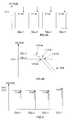
- FIGs. 4A-B and 5 graphically depict charging according to these principles.
- FIG. 4A a graphical depiction of bottom based balancing is shown.
- Four cells from an exemplary battery pack are depicted, although battery packs according to the principles of the present disclosure may have more or fewer cells.
- Each of the four cells is discharged to a predetermined bottom capacity.
- the predetermined bottom capacity is shown as 0.1 Ah.
- FIG. 4B depicts exemplary voltage curves for two cells as they discharge.
- a fully charged cell may have a voltage above 3 V, and the voltage may initially decrease fairly slowly as the cell is discharged. Once the cell's capacity reaches a low level, the voltage will begin to drop quickly.
- This change in voltage decrease rate may be referred to as a knee.
- the voltage knee may correspond to a certain capacity that is fairly consistent across the cells. For example only, the voltage knee may correspond to 0.15 Ah.
- All the cells may then be discharged to the point at which their respective voltage knee is observed, at which time they will have approximately equal capacities.
- monitoring voltage rates quickly and determining derivatives in order to precisely determine the knee may require additional circuitry, adding complexity and cost to an implementation.
- the position of the knee can be approximately determined by monitoring when the cell crosses a voltage threshold that is less than the knee voltage.
- the voltage threshold should therefore be reached fairly soon after the voltage knee, and the point at which the cell voltage crosses the voltage threshold may be a reliable indicator of where the knee voltage was.
- the capacity of the cell may be slightly lower than at the knee voltage. For example, the cell capacity may be 0.1 Ah.
- a threshold voltage of 2.5 V is shown.
- each cell can be discharged until it reaches 2.5 V. Once the cell reaches 2.5 V, discharging can be stopped for that cell.
- the threshold voltage of 2.5 V is for example only. Alternative threshold voltages may be chosen. In addition, threshold voltages may vary based on cell chemistry and construction.
- the cells may be discharged by applying a load across each cell.
- the load may be a constant current load, such as a transistor, or may be a resistive load.
- large loads may be applied to the cells.
- the large load may discharge the cells quickly, but may not allow for an accurate determination of capacity.
- the large load can be applied until the cell reaches a second threshold voltage. Once the cell has reached the second threshold voltage, a smaller load can be applied to the cell until it reaches the threshold voltage, such as 2.5 V in FIGs. 4A-B .
- the cells may all be discharged simultaneously, with the discharging of each cell stopped when it reaches the threshold voltage.
- the second threshold voltage may be set approximately equal to the threshold voltage.
- the large load can be removed from the cell.
- the cell voltage may rebound to a level above the threshold. The cell is then discharged using the smaller load until it once again reaches the threshold voltage.
- a balancing capacitor or capacitors may optionally be sequentially applied across the battery cells.
- the capacitors can precisely equalize the voltages across the cells. Once the cells have been discharged to a common capacity, charging from this bottom balanced condition can begin.
- FIG. 5 a graphical depiction of charging from a bottom balanced state is presented.
- the four exemplary cells which are arranged in series, may be charged by a common current. As the cells increase in capacity, the voltages of the cells may begin to diverge. Once one of the cells reaches a predetermined maximum voltage, charging can be stopped across all cells. At this point, each of the cells should have approximately the same capacity.
- each of the cells has approximately 1.0 Ah of capacity.
- the first three cells only have a voltage of 3.2 V at 1.0 Ah of capacity.
- the threshold voltage of 3.6 V may be chosen, similarly to FIG. 4B , as a voltage that will be crossed during a rapid rise in voltage, which indicates a maximum cell capacity.
- the threshold voltage may be chosen
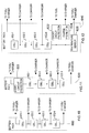
- Control begins in step 200, where a timer is reset.
- Control continues in step 202, where cell voltages are measured.
- the cell voltages may be measured serially using a single measurement device.
- a multiplexer may output the positive and negative terminals of each cell to an analog-to-digital converter (ADC). The multiplexer may then select each of the cells, whose voltage can be measured by the ADC.
- ADC analog-to-digital converter
- Control continues in step 204, where control determines whether cell voltages are less than a lower threshold. For example, control can determine whether any of the cell voltages is less than the lower threshold, or whether an average cell voltage of all the cells is less than the lower threshold. Alternatively, because the cell voltages should track together closely, control may measure only one cell voltage to determine whether it is than lower threshold.
- the bottom balance and charge operation may be that described in FIG. 7 below.
- control determines whether cell voltages are greater than an upper threshold. If so, control transfers to step 208; otherwise, control transfers to step 216.
- step 216 cell voltages are not below a lower threshold, implying that they do not need to be fully discharged and recharged. However, they are less than the upper threshold, and so can be incrementally charged.
- control may determine whether the timer is greater than the threshold. If so, control transfers to step 228; otherwise, control remains in step 208.
- the timer may measure time in terms of days. After a predetermined number of days, such as 30, where the battery pack has remained on the charger, a new bottom balancing charge procedure may be carried out. As such, in step 228, control resets the timer, and then performs bottom balancing and charging, such as according to FIG. 7 .
- Control continues in step 306, where control determines whether any cell has reached a low capacity. If so, control transfers to step 310; otherwise, control transfers to step 314. Control may determine that a cell has reached a low capacity by determining when the voltage across the cell has decreased below a threshold level.
- control determines whether a large load is applied to the cell that has reached the low capacity. If so, control transfers to step 318; otherwise, control transfers to step 322. In step 318, the large load is removed from the cell and the small load is applied to the cell. Control then continues in step 314. Control may be modified by including more than two load sizes. For example only, three or more loads may be sequentially applied when discharging a cell. In addition, the load size may be variable, increasing as the cell capacity decreases.
- step 322 control stops discharging the cell, and control continues in step 314.
- Steps 310 and 318 are optional, and may be used when both large and small loads are used for discharging. If a single load is applied to the cells, step 306 may proceed directly through step 310 to step 322.
- step 314 control determines whether discharging has stopped for all cells. If so, control returns to step 306; otherwise, control transfers to step 326.
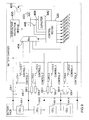
- a battery pack 402 includes four cells, 404-1, 404-2, 404-3, and 404-4.
- the battery pack 402 is shown with four cells 404, although fewer cells may be present.
- the battery pack 402 has been simplified, with no short-circuit protection or any other features shown.
- the ADC 422 converts the analog voltage across the selected cell 404 to a digital value that is output to the control module 418.
- the ADC 422 may sample periodically or may be triggered to sample when the control module 418 selects a new cell 404 using the multiplexer 414.
- the control module 418 controls a current source 426.
- the current source 426 outputs a current to the positive terminal of the cell 404-1 of the battery pack 402. Alternatively, the current may be output to the negative terminal of the cell 404-4.
- the current source 426 may output a predefined current, or may output a current based upon a value from the control module 418.
- load resistors 434-1, 434-2, 434-3, and 434-4 are arranged across the cells 404-1, 404-2, 404-3, and 404-4, respectively.
- the load resistors 434-1, 434-2, 434-3, and 434-4 are controlled by switches 438-1, 438-2, 438-3, and 438-4, respectively.
- the switches 438 are controlled by respective control lines from the control module 418.
- the load resistors 434 dissipate stored energy from the cells 404. While discharging is occurring, the control module 418 monitors the voltages of the cells 404 via the multiplexer 414 and the ADC 422. As each cell 404 reaches the predetermined voltage threshold, the control module 418 instructs the associated switch 438 to disconnect the associated load resistor 454.
- FIG. 8B depicts a configuration where the load resistors 434, the switches 438, 446, and 450, the multiplexer 414, the ADC 422, the capacitor 442, and a control module 460 similar to the control module 418 of FIG. 8A are located in a battery pack 462.
- a battery charger 470 includes the current source 426 and the overvoltage protection module 430.
- a battery charger 502 may include components similar to that of the battery charger 410 of FIG. 8A .
- the battery charger 502 may include first and second load resistors 506 and 508 for each of the cells 404.
- One terminal of the load resistors 506 and 508 is connected to a positive terminal of the associated cell 404.
- the opposite terminals of the load resistors 506 and 508 are connected to the negative terminal of the associated cell via switches 510 and 512, respectively.
- the load resistors 506 may have a low resistance, presenting a large load to the corresponding cell 404.
- the load resistors 508 may have a higher resistance, presenting a lower load to the cells 404.
- both load resistors 506 and 508 may be applied across the cell 404 to create a smaller parallel resistance and therefore a larger load.
- a control module 520 senses the voltage across each of the cells 404.
- the control module 520 may initially apply the large loads 506 to the cells 404. When a cell 404 reaches a predetermined voltage threshold, the control module 520 may disconnect the large load 506 and connect the small load 504. After the small load 504 has been connected, once the cell 404 reaches a second predetermined voltage threshold, the control module 520 disconnects the small load 504.
- Various components of the battery charger 502 may be located within the battery pack 402, similar to the example of FIG. 8B . Referring now to FIG. 10 , a functional block diagram of an exemplary battery pack 600 according to the principles of the present disclosure is presented.
- the battery pack 600 includes multiple cells 602. For purposes of illustration only, the battery pack 600 is shown with four cells 602-1, 602-2, 602-3, and 603-4, though more or fewer are possible.
- the cells 602 each have a positive and negative terminal.
- the positive terminal of the cell 602-1 is connected to an external contact that interfaces with a power tool or a battery charger.
- the negative terminal of the cell 602-4 is connected to an external contact that interfaces with the power tool or the battery charger.
- the negative terminals of the cells 602-1, 602-2, and 603-3 connect to external contacts that interface with the battery charger. Because the battery charger bottom balances the cells 602, and then charges the cells 602 to a common capacity, the battery pack 600 does not need to have a low voltage protection system.
- the battery pack 640 includes short-circuit protection 622.
- the short-circuit protection 622 may be located between the negative terminal of the cell 602-4 and an external contact that interfaces with the tool.
- the positive terminal of the cell 602-1 connects to an external contact that interfaces with the power tool or the battery charger.
- the battery pack 640 may also include a temperature sensor 626 that may be located between the negative terminal of the cell 602-4 and an external contact that can interface with the tool and the charger. In this way, the tool and/or the charger can determine the temperature of the battery pack 640.
- the temperature sensor 626 may include a thermocouple.
- Battery charging according to the principles of the present disclosure may allow battery packs to be produced with very limited electronics, as shown in FIGs. 10-12 . Such charging techniques prevent any one battery cell from prematurely running out of capacity and risking damage. In this way, battery packs may be manufactured, without monitoring electronics, at lower expense and with lower weight. Further, electronics in the battery charger may be less subject to vibration and impact than electronics in a battery pack inserted into a cordless power tool. Advantages in battery life and safety may also be recognized, regardless of whether electronics are located in the battery or battery pack.
Landscapes
- Engineering & Computer Science (AREA)
- General Chemical & Material Sciences (AREA)
- Chemical & Material Sciences (AREA)
- Chemical Kinetics & Catalysis (AREA)
- Electrochemistry (AREA)
- Power Engineering (AREA)
- Manufacturing & Machinery (AREA)
- Life Sciences & Earth Sciences (AREA)
- Sustainable Development (AREA)
- Sustainable Energy (AREA)
- Transportation (AREA)
- Mechanical Engineering (AREA)
- Charge And Discharge Circuits For Batteries Or The Like (AREA)
- Secondary Cells (AREA)
Applications Claiming Priority (1)
| Application Number | Priority Date | Filing Date | Title |
|---|---|---|---|
| US99902407P | 2007-10-15 | 2007-10-15 |
Publications (3)
| Publication Number | Publication Date |
|---|---|
| EP2075893A2 true EP2075893A2 (de) | 2009-07-01 |
| EP2075893A3 EP2075893A3 (de) | 2013-01-16 |
| EP2075893B1 EP2075893B1 (de) | 2016-03-09 |
Family
ID=40303669
Family Applications (1)
| Application Number | Title | Priority Date | Filing Date |
|---|---|---|---|
| EP08166598.6A Ceased EP2075893B1 (de) | 2007-10-15 | 2008-10-14 | Unterseitenbasierter Ausgleich in einem Lithiumionenbatteriesystem |
Country Status (3)
| Country | Link |
|---|---|
| US (2) | US9136716B2 (de) |
| EP (1) | EP2075893B1 (de) |
| CN (1) | CN201466159U (de) |
Cited By (1)
| Publication number | Priority date | Publication date | Assignee | Title |
|---|---|---|---|---|
| EP3680955A1 (de) * | 2019-01-08 | 2020-07-15 | Samsung SDI Co., Ltd. | Batteriesystem |
Families Citing this family (39)
| Publication number | Priority date | Publication date | Assignee | Title |
|---|---|---|---|---|
| DE102009040236A1 (de) * | 2009-09-07 | 2011-03-10 | Volkswagen Ag | Batteriesystem |
| KR101057542B1 (ko) * | 2010-01-26 | 2011-08-17 | 에스비리모티브 주식회사 | 배터리 관리 시스템 및 그 구동 방법 |
| CN102823104B (zh) * | 2010-02-05 | 2016-05-11 | 法国原子能源和替代能源委员会 | 用于电池的充电均衡系统 |
| JP2011212792A (ja) * | 2010-03-31 | 2011-10-27 | Makita Corp | 電動工具 |
| FR2963709B1 (fr) * | 2010-08-05 | 2014-12-26 | E4V | Procede d'equilibrage pour batterie electrique et systeme de gestion pour batterie mettant en oeuvre un tel procede |
| DE102010036002A1 (de) * | 2010-08-31 | 2012-03-01 | Voith Patent Gmbh | System zur Speicherung elektrischer Energie |
| JP5647957B2 (ja) * | 2010-09-10 | 2015-01-07 | 富士フイルム株式会社 | 超音波診断装置 |
| US20120119709A1 (en) * | 2010-11-17 | 2012-05-17 | Tenergy Corporation | Battery pack balancing circuit |
| WO2011103833A2 (zh) * | 2011-04-18 | 2011-09-01 | 华为终端有限公司 | 电池、电池组件及用户设备 |
| JP2012253951A (ja) * | 2011-06-03 | 2012-12-20 | Sony Corp | 電源供給装置、充電方法、充電池モジュール、及び充電装置 |
| JP2013072816A (ja) * | 2011-09-28 | 2013-04-22 | Sanyo Electric Co Ltd | 電源装置とこの電源装置を備える車両 |
| JP5730401B2 (ja) * | 2011-10-28 | 2015-06-10 | ルネサスエレクトロニクス株式会社 | バッテリシステム |
| JP5692040B2 (ja) * | 2011-12-16 | 2015-04-01 | トヨタ自動車株式会社 | 蓄電システム |
| US10539625B2 (en) | 2012-01-16 | 2020-01-21 | Maxim Integrated Products, Inc. | Integrated standard-compliant data acquisition device |
| DE112013000582B4 (de) | 2012-01-16 | 2025-06-05 | Maxim Integrated Products, Inc. | Verfahren und Vorrichtung zur differentiellen Kommunikation |
| KR101715964B1 (ko) * | 2012-06-04 | 2017-03-13 | 삼성에스디아이 주식회사 | 이차 전지 |
| EP2696465B1 (de) * | 2012-08-09 | 2016-12-21 | Samsung SDI Co., Ltd. | Batterieverwaltungssystem und Zellausgleichsverfahren |
| CN103580108B (zh) * | 2012-08-09 | 2017-04-12 | 三星Sdi株式会社 | 电池组及其单元平衡方法和包括该电池组的能量存储系统 |
| WO2014045745A1 (ja) * | 2012-09-18 | 2014-03-27 | Necエナジーデバイス株式会社 | 蓄電システムおよび電池保護方法 |
| CN102842896B (zh) * | 2012-09-29 | 2014-11-26 | 上海空间电源研究所 | 锂离子蓄电池过放保护控制系统及过放保护方法 |
| US9837837B2 (en) * | 2012-11-19 | 2017-12-05 | Byd Company Limited | Protective device and protective system for battery assembly which detects discontinuities through voltage monitoring |
| JP6404640B2 (ja) * | 2014-08-22 | 2018-10-10 | 株式会社マキタ | 電動機械器具用バッテリパック |
| DE102014219582A1 (de) * | 2014-09-26 | 2016-03-31 | Younicos Ag | Verfahren zum Vermessen oder Prüfen der Leistungsfähigkeit von Akkumulatoren |
| US9853473B2 (en) * | 2014-10-13 | 2017-12-26 | Lenovo (Singapore) Pte. Ltd. | Battery pack assembly and method |
| CN106450071B (zh) * | 2015-08-04 | 2019-08-06 | 南京德朔实业有限公司 | 电池包及其与电动工具的组合和连接它们的方法 |
| US9692244B2 (en) * | 2015-09-08 | 2017-06-27 | Yung Ju Lee | Charging means and apparatus for secondary battery |
| DE102017204643A1 (de) * | 2016-05-03 | 2017-11-09 | Robert Bosch Gmbh | Vorrichtung und Verfahren zum Entladen von mindestens einer Akkuzelle einer Handwerkzeugmaschine |
| CN105974243B (zh) * | 2016-06-29 | 2020-02-14 | 国网山东省电力公司 | 一种应用于现场的供电及充电设备的检测系统及方法 |
| JP6883396B2 (ja) * | 2016-08-25 | 2021-06-09 | 矢崎総業株式会社 | 急速充電装置 |
| KR102123048B1 (ko) | 2017-01-10 | 2020-06-15 | 주식회사 엘지화학 | 에너지 절약 및 빠른 셀 밸런싱이 가능한 충전 제어 장치 및 방법 |
| WO2018131874A1 (ko) * | 2017-01-10 | 2018-07-19 | 주식회사 엘지화학 | 에너지 절약 및 빠른 셀 밸런싱이 가능한 충전 제어 장치 및 방법 |
| WO2018183864A1 (en) * | 2017-03-31 | 2018-10-04 | The Noco Company | Portable or hand held vehicle battery jump starting apparatus with battery cell equalization circuit |
| CN111527664B (zh) * | 2018-03-01 | 2023-06-30 | 株式会社村田制作所 | 电池组 |
| CN110682831B (zh) * | 2018-06-19 | 2021-05-14 | 广州汽车集团股份有限公司 | 一种车载动力电池均衡方法、装置及汽车 |
| DE102018210524A1 (de) * | 2018-06-27 | 2020-01-02 | Robert Bosch Gmbh | Verfahren zum Aufladen von Akkupacks für Elektrowerkzeugmaschinen sowie Ladegerät zur Durchführung des Verfahrens |
| WO2021178428A1 (en) * | 2020-03-05 | 2021-09-10 | Milwaukee Electric Tool Corporation | Battery module-level balancing of portable power supply |
| JP7484870B2 (ja) * | 2021-11-01 | 2024-05-16 | トヨタ自動車株式会社 | 組電池の劣化診断装置、及び組電池の劣化診断方法 |
| CN114665562A (zh) * | 2022-04-13 | 2022-06-24 | 广州蓝奇电子实业有限公司 | 一种用于电池串联充放电设备的过压保护方法 |
| CN118914903B (zh) * | 2024-08-20 | 2026-02-10 | 岚图汽车科技股份有限公司 | 电池内部安全性测试方法、装置、设备及存储介质 |
Citations (2)
| Publication number | Priority date | Publication date | Assignee | Title |
|---|---|---|---|---|
| DE20107438U1 (de) | 2001-04-30 | 2001-12-13 | ErgoVita GmbH & Co. KG Europäisches Institut für betriebliche und individuelle Gesundheitsförderung Dipl.-Ing. Robert Seibt, 09419 Thum-Jahnsbach | Lade- und Entladegerät für Akkumulatoren |
| US20050127873A1 (en) | 2003-12-11 | 2005-06-16 | Hiroyoshi Yamamoto | Battery charging method |
Family Cites Families (29)
| Publication number | Priority date | Publication date | Assignee | Title |
|---|---|---|---|---|
| US685041A (en) * | 1901-07-31 | 1901-10-22 | Louis C Gerken | Washing-rubber. |
| GB1461616A (en) * | 1973-04-10 | 1977-01-13 | Mabuchi Motor Co | Battery equalizing discharger |
| US5680026A (en) * | 1994-03-21 | 1997-10-21 | Tyton Corporation | Tool belt with battery assembly |
| US5914585A (en) * | 1996-02-20 | 1999-06-22 | Norand Corporation | Power sharing in computing systems with a plurality of electronic devices |
| US5764027A (en) * | 1996-06-21 | 1998-06-09 | Ford Global Technologies, Inc. | Method and apparatus for battery charge balancing |
| US5811959A (en) * | 1996-12-27 | 1998-09-22 | Kejha; Joseph B. | Smart circuit board for multicell battery protection |
| AU5320599A (en) * | 1998-07-27 | 2000-02-21 | Midtronics, Inc. | Apparatus and method for carrying out diagnostic tests on batteries and for rapidly charging batteries |
| US6137260A (en) * | 1999-01-29 | 2000-10-24 | Intermec Ip Corp. | Multifunction connector for hand-held terminal docks |
| JP3869585B2 (ja) * | 1999-07-30 | 2007-01-17 | 三洋電機株式会社 | 複数の二次電池の放電方法と組電池 |
| DE10107619A1 (de) * | 2001-02-17 | 2003-01-30 | Julian Habigt | Mikrocontrollergesteuertes Ladegerät zur schonenden Ladung mehrzelliger Akkupacks |
| FR2825842B1 (fr) * | 2001-06-07 | 2003-10-03 | Cit Alcatel | Procede d'equilibrage pour batterie electrique sousmise a un regime discontinu de recharge et systeme de gestion de batterie permettant la mise en oeuvre de ce procede |
| JP4605952B2 (ja) * | 2001-08-29 | 2011-01-05 | 株式会社日立製作所 | 蓄電装置及びその制御方法 |
| JP3879494B2 (ja) | 2001-11-22 | 2007-02-14 | 日立工機株式会社 | 電池パック |
| US6798170B2 (en) * | 2002-02-08 | 2004-09-28 | Valence Technology, Inc. | Electrical power source apparatuses, circuits, electrochemical device charging methods, and methods of charging a plurality of electrochemical devices |
| US7061207B2 (en) * | 2002-08-09 | 2006-06-13 | H2Eye (International ) Limited | Cell equalizing circuit |
| US6894457B2 (en) * | 2002-11-01 | 2005-05-17 | American Power Conversion Corporation | Universal multiple device power adapter and carry case |
| US7157882B2 (en) * | 2002-11-22 | 2007-01-02 | Milwaukee Electric Tool Corporation | Method and system for battery protection employing a selectively-actuated switch |
| US7253585B2 (en) * | 2002-11-22 | 2007-08-07 | Milwaukee Electric Tool Corporation | Battery pack |
| JP4035777B2 (ja) * | 2003-02-10 | 2008-01-23 | 株式会社デンソー | 組電池の放電装置 |
| US20050024021A1 (en) * | 2003-05-07 | 2005-02-03 | Milwaukee Electric Tool Corporation | Battery charger and assembly |
| JP2007520180A (ja) * | 2003-10-14 | 2007-07-19 | ブラック アンド デッカー インク | 電池パックの障害状態からの保護を提供するべく適合された二次電池、電動工具、充電器、及び電池パック用の保護方法、保護回路、及び保護装置 |
| US7126312B2 (en) * | 2004-07-28 | 2006-10-24 | Enerdel, Inc. | Method and apparatus for balancing multi-cell lithium battery systems |
| JP4195026B2 (ja) * | 2005-08-24 | 2008-12-10 | 矢崎総業株式会社 | 組電池の充電状態調整装置 |
| US7279867B2 (en) * | 2005-12-02 | 2007-10-09 | Southwest Electronic Energy Corporation | Method for balancing cells or groups of cells in a battery pack |
| US7893657B2 (en) * | 2006-12-19 | 2011-02-22 | Anand Kumar Chavakula | Multi-power charger and battery backup system |
| US7598706B2 (en) * | 2007-01-26 | 2009-10-06 | General Electric Company | Cell balancing battery pack and method of balancing the cells of a battery |
| US7782013B2 (en) * | 2007-04-17 | 2010-08-24 | Chun-Chieh Chang | Rechargeable battery assembly and method for recharging same |
| US7855528B2 (en) * | 2007-04-18 | 2010-12-21 | Powertech Industrial Co., Ltd. | Power supply for portable apparatuses |
| US20090179615A1 (en) * | 2008-01-11 | 2009-07-16 | Grofam-Amron | Universal battery charger |
-
2008
- 2008-10-14 US US12/250,673 patent/US9136716B2/en active Active
- 2008-10-14 EP EP08166598.6A patent/EP2075893B1/de not_active Ceased
- 2008-10-15 CN CN2008201798733U patent/CN201466159U/zh not_active Expired - Fee Related
-
2015
- 2015-08-07 US US14/820,682 patent/US20150349551A1/en not_active Abandoned
Patent Citations (2)
| Publication number | Priority date | Publication date | Assignee | Title |
|---|---|---|---|---|
| DE20107438U1 (de) | 2001-04-30 | 2001-12-13 | ErgoVita GmbH & Co. KG Europäisches Institut für betriebliche und individuelle Gesundheitsförderung Dipl.-Ing. Robert Seibt, 09419 Thum-Jahnsbach | Lade- und Entladegerät für Akkumulatoren |
| US20050127873A1 (en) | 2003-12-11 | 2005-06-16 | Hiroyoshi Yamamoto | Battery charging method |
Cited By (1)
| Publication number | Priority date | Publication date | Assignee | Title |
|---|---|---|---|---|
| EP3680955A1 (de) * | 2019-01-08 | 2020-07-15 | Samsung SDI Co., Ltd. | Batteriesystem |
Also Published As
| Publication number | Publication date |
|---|---|
| US9136716B2 (en) | 2015-09-15 |
| EP2075893A3 (de) | 2013-01-16 |
| US20090096419A1 (en) | 2009-04-16 |
| US20150349551A1 (en) | 2015-12-03 |
| EP2075893B1 (de) | 2016-03-09 |
| CN201466159U (zh) | 2010-05-12 |
Similar Documents
| Publication | Publication Date | Title |
|---|---|---|
| EP2075893B1 (de) | Unterseitenbasierter Ausgleich in einem Lithiumionenbatteriesystem | |
| EP2418751B1 (de) | Batterieladegerät und Batterieladeverfahren | |
| KR101497602B1 (ko) | 배터리 밸런싱 시스템 및 이를 이용한 배터리 밸런싱 방법 | |
| EP3618221B1 (de) | Vorrichtung zum batterieausgleich und batteriepack damit | |
| US10873201B2 (en) | Battery management apparatus and method for protecting a lithium iron phosphate cell from over-voltage using the same | |
| RU2736777C1 (ru) | Способ зарядки или разрядки накопителя энергии | |
| US7598706B2 (en) | Cell balancing battery pack and method of balancing the cells of a battery | |
| EP2618454B1 (de) | Vorrichtung zur mittelung der zellspannung mehrerer batteriepacks | |
| KR102758018B1 (ko) | 배터리 관리 시스템, 배터리 팩, 에너지 저장 시스템 및 배터리 관리 방법 | |
| CN104204832B (zh) | 用于互连电池组中的电池组电池的方法、电池组和监控装置 | |
| KR101916969B1 (ko) | 배터리의 충전 방법 및 이에 따른 배터리 팩 | |
| EP2416469A1 (de) | Ladegerät | |
| EP2645527A1 (de) | Batteriepack | |
| US20130057224A1 (en) | Control system of battery pack and method of charging and discharging using the same | |
| JP2014027867A (ja) | バッテリーの充電パラメータの制御方法およびバッテリー充電システム | |
| US9184600B2 (en) | Method for balancing the voltages of electrochemical cells connected in several parallel branches | |
| EP2731165A1 (de) | Verfahren zur herstellung eines batteriepacks und batteriepack | |
| CN101504996A (zh) | 充电装置和充电方法 | |
| CN102027655A (zh) | 用于检测电池或电容串联组中的电池单元充电状态和放电状态的散度的方法 | |
| JP2021044918A (ja) | 電池制御ユニットおよび電池システム | |
| KR102045047B1 (ko) | 배터리 모듈의 soh 불균형을 고려한 최대용량 충전장치 및 그 제어방법 | |
| EP3635841A1 (de) | Umgebungstemperaturabhängiges batterieladeverfahren und -system | |
| WO2012019185A2 (en) | Lithium polymer battery charger and methods therefor | |
| JP2011188700A (ja) | 電源システム、放電制御方法および放電制御プログラム | |
| JP5165405B2 (ja) | 充電制御回路、電池パック、及び充電システム |
Legal Events
| Date | Code | Title | Description |
|---|---|---|---|
| PUAI | Public reference made under article 153(3) epc to a published international application that has entered the european phase |
Free format text: ORIGINAL CODE: 0009012 |
|
| AK | Designated contracting states |
Kind code of ref document: A2 Designated state(s): AT BE BG CH CY CZ DE DK EE ES FI FR GB GR HR HU IE IS IT LI LT LU LV MC MT NL NO PL PT RO SE SI SK TR |
|
| AX | Request for extension of the european patent |
Extension state: AL BA MK RS |
|
| PUAL | Search report despatched |
Free format text: ORIGINAL CODE: 0009013 |
|
| AK | Designated contracting states |
Kind code of ref document: A3 Designated state(s): AT BE BG CH CY CZ DE DK EE ES FI FR GB GR HR HU IE IS IT LI LT LU LV MC MT NL NO PL PT RO SE SI SK TR |
|
| AX | Request for extension of the european patent |
Extension state: AL BA MK RS |
|
| RIC1 | Information provided on ipc code assigned before grant |
Ipc: H01M 10/48 20060101ALI20121213BHEP Ipc: B60L 11/18 20060101ALI20121213BHEP Ipc: H02J 7/00 20060101AFI20121213BHEP |
|
| 17P | Request for examination filed |
Effective date: 20130628 |
|
| RBV | Designated contracting states (corrected) |
Designated state(s): AT BE BG CH CY CZ DE DK EE ES FI FR GB GR HR HU IE IS IT LI LT LU LV MC MT NL NO PL PT RO SE SI SK TR |
|
| AKX | Designation fees paid |
Designated state(s): DE GB |
|
| 17Q | First examination report despatched |
Effective date: 20140318 |
|
| GRAP | Despatch of communication of intention to grant a patent |
Free format text: ORIGINAL CODE: EPIDOSNIGR1 |
|
| INTG | Intention to grant announced |
Effective date: 20150824 |
|
| GRAS | Grant fee paid |
Free format text: ORIGINAL CODE: EPIDOSNIGR3 |
|
| GRAA | (expected) grant |
Free format text: ORIGINAL CODE: 0009210 |
|
| AK | Designated contracting states |
Kind code of ref document: B1 Designated state(s): DE GB |
|
| REG | Reference to a national code |
Ref country code: GB Ref legal event code: FG4D |
|
| REG | Reference to a national code |
Ref country code: DE Ref legal event code: R096 Ref document number: 602008042657 Country of ref document: DE |
|
| REG | Reference to a national code |
Ref country code: DE Ref legal event code: R097 Ref document number: 602008042657 Country of ref document: DE |
|
| PLBE | No opposition filed within time limit |
Free format text: ORIGINAL CODE: 0009261 |
|
| STAA | Information on the status of an ep patent application or granted ep patent |
Free format text: STATUS: NO OPPOSITION FILED WITHIN TIME LIMIT |
|
| 26N | No opposition filed |
Effective date: 20161212 |
|
| PGFP | Annual fee paid to national office [announced via postgrant information from national office to epo] |
Ref country code: GB Payment date: 20210907 Year of fee payment: 14 |
|
| PGFP | Annual fee paid to national office [announced via postgrant information from national office to epo] |
Ref country code: DE Payment date: 20210831 Year of fee payment: 14 |
|
| REG | Reference to a national code |
Ref country code: DE Ref legal event code: R119 Ref document number: 602008042657 Country of ref document: DE |
|
| GBPC | Gb: european patent ceased through non-payment of renewal fee |
Effective date: 20221014 |
|
| PG25 | Lapsed in a contracting state [announced via postgrant information from national office to epo] |
Ref country code: DE Free format text: LAPSE BECAUSE OF NON-PAYMENT OF DUE FEES Effective date: 20230503 |
|
| PG25 | Lapsed in a contracting state [announced via postgrant information from national office to epo] |
Ref country code: GB Free format text: LAPSE BECAUSE OF NON-PAYMENT OF DUE FEES Effective date: 20221014 |