EP2075898A1 - Ensemble d'aimant permanent et son procédé de fabrication - Google Patents
Ensemble d'aimant permanent et son procédé de fabrication Download PDFInfo
- Publication number
- EP2075898A1 EP2075898A1 EP08171650A EP08171650A EP2075898A1 EP 2075898 A1 EP2075898 A1 EP 2075898A1 EP 08171650 A EP08171650 A EP 08171650A EP 08171650 A EP08171650 A EP 08171650A EP 2075898 A1 EP2075898 A1 EP 2075898A1
- Authority
- EP
- European Patent Office
- Prior art keywords
- permanent magnet
- encapsulating element
- encapsulating
- rotor
- assembly
- Prior art date
- Legal status (The legal status is an assumption and is not a legal conclusion. Google has not performed a legal analysis and makes no representation as to the accuracy of the status listed.)
- Granted
Links
- 238000004519 manufacturing process Methods 0.000 title description 6
- 230000005291 magnetic effect Effects 0.000 claims abstract description 88
- 238000000429 assembly Methods 0.000 claims abstract description 21
- 230000000712 assembly Effects 0.000 claims abstract description 21
- 239000000463 material Substances 0.000 claims description 11
- 239000007769 metal material Substances 0.000 claims description 8
- 229920003023 plastic Polymers 0.000 claims description 5
- 239000004033 plastic Substances 0.000 claims description 5
- 239000004593 Epoxy Substances 0.000 claims description 4
- 230000005294 ferromagnetic effect Effects 0.000 claims description 4
- 239000004677 Nylon Substances 0.000 claims description 3
- 239000004952 Polyamide Substances 0.000 claims description 3
- 229920001778 nylon Polymers 0.000 claims description 3
- 229920002647 polyamide Polymers 0.000 claims description 3
- 229920000515 polycarbonate Polymers 0.000 claims description 3
- 239000004417 polycarbonate Substances 0.000 claims description 3
- 229920000728 polyester Polymers 0.000 claims description 3
- 229920002635 polyurethane Polymers 0.000 claims description 3
- 239000004814 polyurethane Substances 0.000 claims description 3
- 125000000391 vinyl group Chemical group [H]C([*])=C([H])[H] 0.000 claims description 3
- 229920002554 vinyl polymer Polymers 0.000 claims description 3
- 239000002990 reinforced plastic Substances 0.000 claims description 2
- 230000001419 dependent effect Effects 0.000 claims 2
- 238000005260 corrosion Methods 0.000 description 15
- 230000007797 corrosion Effects 0.000 description 15
- 238000000034 method Methods 0.000 description 9
- 229920002430 Fibre-reinforced plastic Polymers 0.000 description 7
- 239000011151 fibre-reinforced plastic Substances 0.000 description 7
- 238000010168 coupling process Methods 0.000 description 4
- 239000011241 protective layer Substances 0.000 description 4
- 230000008878 coupling Effects 0.000 description 3
- 238000005859 coupling reaction Methods 0.000 description 3
- 239000011152 fibreglass Substances 0.000 description 3
- PXHVJJICTQNCMI-UHFFFAOYSA-N Nickel Chemical compound [Ni] PXHVJJICTQNCMI-UHFFFAOYSA-N 0.000 description 2
- 230000002411 adverse Effects 0.000 description 2
- 238000005452 bending Methods 0.000 description 2
- 230000007613 environmental effect Effects 0.000 description 2
- 230000004907 flux Effects 0.000 description 2
- 238000000465 moulding Methods 0.000 description 2
- 229910001172 neodymium magnet Inorganic materials 0.000 description 2
- 229920000642 polymer Polymers 0.000 description 2
- 229910000831 Steel Inorganic materials 0.000 description 1
- QJVKUMXDEUEQLH-UHFFFAOYSA-N [B].[Fe].[Nd] Chemical compound [B].[Fe].[Nd] QJVKUMXDEUEQLH-UHFFFAOYSA-N 0.000 description 1
- 230000003466 anti-cipated effect Effects 0.000 description 1
- 238000000576 coating method Methods 0.000 description 1
- 230000000694 effects Effects 0.000 description 1
- 239000000835 fiber Substances 0.000 description 1
- 238000009434 installation Methods 0.000 description 1
- 239000010410 layer Substances 0.000 description 1
- 230000004048 modification Effects 0.000 description 1
- 238000012986 modification Methods 0.000 description 1
- 229910052759 nickel Inorganic materials 0.000 description 1
- 230000002093 peripheral effect Effects 0.000 description 1
- 238000007747 plating Methods 0.000 description 1
- 230000002265 prevention Effects 0.000 description 1
- 230000001681 protective effect Effects 0.000 description 1
- 230000002787 reinforcement Effects 0.000 description 1
- 239000010959 steel Substances 0.000 description 1
- 239000012780 transparent material Substances 0.000 description 1
Images

Classifications
-
- H—ELECTRICITY
- H02—GENERATION; CONVERSION OR DISTRIBUTION OF ELECTRIC POWER
- H02K—DYNAMO-ELECTRIC MACHINES
- H02K1/00—Details of the magnetic circuit
- H02K1/06—Details of the magnetic circuit characterised by the shape, form or construction
- H02K1/22—Rotating parts of the magnetic circuit
- H02K1/27—Rotor cores with permanent magnets
- H02K1/2706—Inner rotors
- H02K1/272—Inner rotors the magnetisation axis of the magnets being perpendicular to the rotor axis
- H02K1/274—Inner rotors the magnetisation axis of the magnets being perpendicular to the rotor axis the rotor consisting of two or more circumferentially positioned magnets
- H02K1/2753—Inner rotors the magnetisation axis of the magnets being perpendicular to the rotor axis the rotor consisting of two or more circumferentially positioned magnets the rotor consisting of magnets or groups of magnets arranged with alternating polarity
- H02K1/278—Surface mounted magnets; Inset magnets
- H02K1/2781—Magnets shaped to vary the mechanical air gap between the magnets and the stator
-
- H—ELECTRICITY
- H02—GENERATION; CONVERSION OR DISTRIBUTION OF ELECTRIC POWER
- H02K—DYNAMO-ELECTRIC MACHINES
- H02K15/00—Processes or apparatus specially adapted for manufacturing, assembling, maintaining or repairing of dynamo-electric machines
- H02K15/02—Processes or apparatus specially adapted for manufacturing, assembling, maintaining or repairing of dynamo-electric machines of stator or rotor bodies
- H02K15/03—Processes or apparatus specially adapted for manufacturing, assembling, maintaining or repairing of dynamo-electric machines of stator or rotor bodies having permanent magnets
-
- Y—GENERAL TAGGING OF NEW TECHNOLOGICAL DEVELOPMENTS; GENERAL TAGGING OF CROSS-SECTIONAL TECHNOLOGIES SPANNING OVER SEVERAL SECTIONS OF THE IPC; TECHNICAL SUBJECTS COVERED BY FORMER USPC CROSS-REFERENCE ART COLLECTIONS [XRACs] AND DIGESTS
- Y02—TECHNOLOGIES OR APPLICATIONS FOR MITIGATION OR ADAPTATION AGAINST CLIMATE CHANGE
- Y02E—REDUCTION OF GREENHOUSE GAS [GHG] EMISSIONS, RELATED TO ENERGY GENERATION, TRANSMISSION OR DISTRIBUTION
- Y02E10/00—Energy generation through renewable energy sources
- Y02E10/70—Wind energy
- Y02E10/72—Wind turbines with rotation axis in wind direction
Definitions
- the field of the invention relates generally to permanent magnet assemblies, and more particularly, to permanent magnet assemblies and methods of manufacturing the same for use in electric machines.
- Some known electric machines e.g., those used with electric utility class wind generators and other applications, use large diameter rotors (i.e., rotors having a diameter of two feet or greater).
- large diameter rotors i.e., rotors having a diameter of two feet or greater.
- One example of such an electric machine is a 2-10 megawatt, medium speed (e.g., 100-400 rpm) permanent magnet generator for wind turbines.
- Known large diameter rotors generally include a plurality of permanent magnet assemblies. At least some known permanent magnet assemblies are formed from multiple magnetic blocks that are secured to the rotor.
- known magnetic blocks which are typically made from Neodymium Iron Boron (NdFeB), may not be adequately protected from the environment, and as such, over time such magnets may be vulnerable to corrosion. Corroded magnetic blocks may flake, crack, crumble, or otherwise degrade. Corrosion of the magnetic blocks may adversely reduce the reliability and life of the electric machine.
- the magnetic blocks are coated with a thin protective layer.
- the magnetic blocks can be coated with approximately 10-30 micrometers of an epoxy or nickel plating.
- the protective layer may be easily damaged during handling of the magnetic blocks and more particularly, may be damaged during assembly of the electric machine (e.g., attaching the magnetic blocks to the rotor). The damaged portions of the layer may leave the magnetic blocks susceptible to corrosion.
- the thin protective layers that are sometimes used may be inadequate to protect the magnetic blocks from corrosion.
- some magnetic blocks are covered with plastic across all of their outwardly-facing surfaces.
- the surface of the magnetic blocks adapted for face-to-face engagement with the rotor is left uncovered because the plastic may adversely effect the magnetic flux between the magnetic blocks and the rotor.
- the uncovered surface is vulnerable to corrosion.
- a sealed metallic retaining can or ring is often used to secure the magnetic blocks in position, as well as to provide additional corrosion protection.
- Such retaining cans and rings are not feasible for use in large diameter machines as the cans and rings may be easily damaged during their installation thereby making them difficult to install on large diameter machines.
- the magnetic blocks are secured directly to the rotor using fiberglass banding.
- banding generally is not used with large diameter rotors because it takes a long time for the fiberglass to cure.
- the ovens that must be used to cure such a rotor are large and are expensive to construct and maintain.
- such ovens generally require large amount of energy.
- the fiberglass may not prevent circumferential movement of the magnetic blocks with respect to the rotor.
- a permanent magnet rotor assembly for use with an electric machine.
- the rotor assembly generally comprises a rotor and a plurality of permanent magnet pole assemblies positioned against the rotor.
- Each of the permanent magnet pole assemblies comprises a magnetic block and an encapsulating member that completely encapsulates the magnetic block.
- a permanent magnet pole assembly is for a permanent magnet rotor assembly including a rotor.
- the permanent magnet pole assembly generally comprises a plurality of magnetic blocks and an encapsulating element underlying the plurality of blocks such that the encapsulating element extends between the plurality of magnetic blocks and the rotor when the permanent magnet pole assembly is positioned against the rotor.
- a method of manufacturing a permanent magnet pole assembly generally comprises providing a first encapsulating element, positioning at least one magnetic block within a portion of the first encapsulating element, and coupling a second encapsulating element to the first encapsulating element such that the first and second encapsulating elements cooperate to completely encapsulate the at least one magnetic block to facilitate protecting the at least one magnetic block from corrosion.
- Figure 1 is a perspective view of a portion of an exemplary permanent magnet rotor assembly 10 for an electrical machine (not shown).
- magnet rotor assembly 10 includes a rotor 12 and a plurality of permanent magnet pole assemblies 14 that are each coupled to rotor 12.
- each permanent magnet pole assembly 14 is coupled to rotor 12 using a plurality of mechanical fasteners (not shown), such as, but not limited to, bolts.
- assemblies 14 can be coupled to rotor 12 using any other known coupling method, such as but not limited to bonding or clamping.
- magnet rotor assemblies 14 are suitable for use with large diameter electric machines, such as, for example, high pole count electric machines that are useful for low/medium speed drives, such as direct-drive multi-megawatt wind generators.
- large diameter machine uses a rotor having a diameter of approximately two feet or larger.
- magnet rotor assemblies 14 can be used with other types of electric machines without departing from the scope of the invention.
- permanent magnet pole assemblies 14 can be used in single and/or double-sided rotors, and in both inner-rotor and outer-rotor topologies.
- FIG. 2 is a cross sectional view of one permanent magnet pole assembly 14 removed from rotor 12.
- each permanent magnetic pole assembly 14 includes a plurality of magnetic blocks 16 and an encapsulating member 20 that substantially encapsulates each magnetic block 16 to facilitate preventing blocks 16 from corroding.
- each permanent magnetic pole assembly 14 includes four magnetic blocks 16.
- pole assembly 14 may include more or less than four magnetic blocks 16.
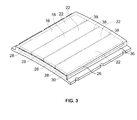
- each magnetic block 16 includes a top 22, a bottom 24, two sides 26 and two opposite ends 28 (shown in Figure 3 ).
- each top 22, bottom 24, side 26 and end 28 of magnetic blocks 16 is substantially planar.
- the magnetic blocks 16 can be fabricated with a bottom 24 that is contoured with a shape that substantially matches the contour of an outer surface of rotor 12 (shown in Figure 1 ).
- the number, size, and shape of magnetic blocks 16 are variably selected, based on the size of rotor 12 and the anticipated electrical losses in magnetic blocks 16.
- magnetic blocks 16 can have any shape that enables assembly 14 to function as described herein. For example, smaller magnetic blocks generally have lower electrical losses per unit area (loss densities) than larger magnetic blocks.
- encapsulating member 20 includes a first encapsulating element 30 and a second encapsulating element 32 that extends from first encapsulating element 30.
- First and second encapsulating elements 30 and 32 respectively, cooperative to form a protective cover that substantially encapsulates magnetic blocks 16 and shields each magnetic block 16 from the environment to facilitate preventing or minimizing corrosion of magnetic blocks 16.
- first encapsulating element 30 underlies magnetic blocks 16, and second encapsulating element 32 overlies the magnetic block 16.
- first and second elements 30 and 32 respectively, could be arranged in any orientation or configuration that enables encapsulating member 20 to function as described herein.
- encapsulating member 20 includes more than two elements 30 and 32.
- Figure 3 is a perspective view of pole assembly 14 with second encapsulating element 32 being fabricated from a semi-transparent material.
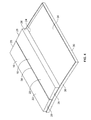
- Figure 4 is a perspective view of assembly 14 with element 32 and two magnetic blocks 16 each removed.
- first encapsulating element 30 is a tray that has a base 34 and a periphery flange 36 that extends upward from an outer periphery of base 34.
- Periphery flange 36 may be formed by bending edges of base 34 upward to form a flange that extends about the perimeter of the base.
- element 30 is sized and shaped to receive magnetic blocks 16 in side-by-side relationship such that an optional gap 38 is defined between each pair of adjacent magnetic blocks 16.
- magnetic blocks 16 are positioned on tray base 34 such that each block bottom 24 is oriented in a substantial face-to-face engagement against the tray.
- the tray is sized to receive four magnetic blocks 16 such that periphery flange 36 extends around the four blocks 16.
- a lower surface of tray base 34 is contoured with a shape that enables the tray to substantially conform to the contoured outer surface of the rotor 12 to which the permanent magnetic pole assembly 14 is mounted.
- the tray is fabricated from a metallic material and first encapsulating element 30 has a greater corrosion resistance than that of the magnetic blocks 16.
- first encapsulating element 30 is fabricated from a ferromagnetic sheet steel.
- other types of metallic materials can be used to fabricate first encapsulating element 30.
- second encapsulating element 32 is fabricated from a fiber-reinforced polymer that extends from first encapsulating element 30. More specifically, in the exemplary embodiment, the fiber-reinforced polymer is molded onto first encapsulating element 30 and onto magnetic blocks 16 such that blocks 16 are encapsulated by element 30. Moreover, in the exemplary embodiment, the fiber-reinforced polymer extends over and covers the top 22, sides 26, and ends 28 of each magnetic block 16. As a result, element 30 substantially seals each gap 38 defined between each adjacent pair of magnetic blocks 16.
- second encapsulating element 32 can be coupled to, or extend from, element 30 in other ways besides being molded directly to first encapsulating element 30 and magnetic blocks 16.
- a thickness of the fiber-reinforced polymer between adjacent magnetic blocks 16, and an airgap of the electric machine (not shown) is preferably as thin as is allowed by mechanical requirements to facilitate maximizing the efficiency of the magnetic flux paths defined within pole assembly 14.
- Suitable polymers for use in the fiber-reinforced polymer of second encapsulating element 32 include, but are not limited to only including, polyamide, polyurethane, polyester, vinyl, nylon, polycarbonate, and/or epoxy.
- the fiber-reinforced polymer may also be a laminate.
- second encapsulating element 32 is formed from a polymer and does not include fiber reinforcement.
- encapsulating member 20 completely encapsulates magnetic blocks 16, magnetic blocks 16 are substantially protected from environmental conditions that may cause corrosion.
- the improved corrosion protection facilitates increasing the reliability and useful life of the electric machine.
- known wind turbine generators having large diameter rotors generally have enclosures ratings of IP54 as set forth by the International Electrotechnical Commission's (IEC)'s standard 60529.
- the enclosure rating is a rating of the degree of protection provided by such enclosures.
- Permanent magnetic pole assemblies 14 fabricated in accordance with the present invention potentially enable an enclosure to be used that has less stringent requirements, such as an enclosure rating of IP23, without sacrificing any level of protection.
- such enclosures facilitate the use of a wind turbine generator that is less costly to manufacture, to maintain, and to operate as compared to known wind turbine generators that use enclosures that have a greater enclosure rating.
- Permanent magnetic pole assemblies 14 can be manufactured by initially providing first encapsulating element 30, and then positioning at least one magnetic block 16 within first encapsulating element 30. Second encapsulating element 32 is then coupled to, or extended from, first encapsulating element 30. As described above, first and second encapsulating elements 30 and 32, respectively, cooperate to completely encapsulate magnetic blocks 16 such that blocks 16 are substantially shielded from environmental conditions that may cause corrosion. In the exemplary embodiments described herein, magnetic blocks 16 are positioned within a generally, flat (or contoured) tray such that adjacent blocks 16 are in a side-by-side relationship with each other, and are in substantial face-to-face contact with the tray.
- second encapsulating element 32 extends from, and is coupled to, the first encapsulating element 30 through a molding process in which a fiber-reinforced polymer is extruded over each magnetic block 16 and over first encapsulating element 30.
- the encapsulating member 20 as described herein facilitates the prevention of magnetic blocks 16 from corrosion. More specifically, the encapsulating member 20, as described above, substantially encapsulates the magnetic blocks 16 and shields each magnetic block 16 from the environment.
Landscapes
- Engineering & Computer Science (AREA)
- Power Engineering (AREA)
- Manufacturing & Machinery (AREA)
- Permanent Field Magnets Of Synchronous Machinery (AREA)
- Iron Core Of Rotating Electric Machines (AREA)
Applications Claiming Priority (1)
| Application Number | Priority Date | Filing Date | Title |
|---|---|---|---|
| US11/967,747 US7781932B2 (en) | 2007-12-31 | 2007-12-31 | Permanent magnet assembly and method of manufacturing same |
Publications (2)
| Publication Number | Publication Date |
|---|---|
| EP2075898A1 true EP2075898A1 (fr) | 2009-07-01 |
| EP2075898B1 EP2075898B1 (fr) | 2014-12-03 |
Family
ID=40568771
Family Applications (1)
| Application Number | Title | Priority Date | Filing Date |
|---|---|---|---|
| EP08171650.8A Not-in-force EP2075898B1 (fr) | 2007-12-31 | 2008-12-15 | Ensemble d'aimants permanents et son procédé de fabrication |
Country Status (4)
| Country | Link |
|---|---|
| US (1) | US7781932B2 (fr) |
| EP (1) | EP2075898B1 (fr) |
| CN (1) | CN101478186B (fr) |
| DK (1) | DK2075898T3 (fr) |
Cited By (4)
| Publication number | Priority date | Publication date | Assignee | Title |
|---|---|---|---|---|
| WO2011129702A1 (fr) * | 2010-04-13 | 2011-10-20 | Smartmotor As | Dispositif et procédé de protection, montage et retenue de pôle magnétique |
| EP3402046A1 (fr) * | 2017-05-10 | 2018-11-14 | GE Renewable Technologies Wind B.V. | Modules à aimants permanents |
| EP3402045A1 (fr) * | 2017-05-10 | 2018-11-14 | GE Renewable Technologies Wind B.V. | Modules à aimants permanents |
| DE102019116641A1 (de) * | 2019-06-19 | 2020-12-24 | Schütz Gmbh & Co Kgaa | Magnetbaugruppe sowie Magnetbaugruppenverbund und Rotor für einen elektrischen Generator mit einem derartigen Magnetbaugruppenverbund |
Families Citing this family (39)
| Publication number | Priority date | Publication date | Assignee | Title |
|---|---|---|---|---|
| FI121614B (fi) * | 2008-12-17 | 2011-01-31 | Switch Drive Systems Oy | Kestomagneettimoduuli sähkökonetta varten |
| CN102292897B (zh) | 2009-01-16 | 2014-04-02 | 科尔风力发电公司 | 用于轴向场装置的扇块式定子 |
| FI20090115A0 (fi) * | 2009-03-25 | 2009-03-25 | Abb Oy | Kestomagnetoitu sähkökone ja kestomagneetti sähkökonetta varten |
| JP2013520149A (ja) * | 2010-02-16 | 2013-05-30 | シーメンス アクチエンゲゼルシヤフト | 発電機の一部の組み立て方法、発電機および風車 |
| US9154024B2 (en) | 2010-06-02 | 2015-10-06 | Boulder Wind Power, Inc. | Systems and methods for improved direct drive generators |
| DE102010038922B4 (de) * | 2010-08-04 | 2017-05-18 | Siemens Aktiengesellschaft | Rotor für eine elektrische Maschine |
| EP2697895B1 (fr) | 2011-04-13 | 2019-09-04 | Boulder Wind Power, Inc. | Agencements de focalisation de flux pour aimants permanents, leurs procédés de fabrication et machines comprenant de tels agencements |
| CN102738980A (zh) * | 2011-04-14 | 2012-10-17 | 侯学青 | 直流永磁无刷无位置传感器电机中绝缘转子的加工方法 |
| EP2523316B8 (fr) | 2011-05-11 | 2014-11-19 | ALSTOM Renewable Technologies | Rotor de générateur, procédé d'assemblage et dispositif d'insertion correspondant |
| DE102011077554A1 (de) * | 2011-06-15 | 2012-12-20 | Siemens Aktiengesellschaft | Permanenterregte dynamoelektrische Maschine, insbesondere direkt angetriebener Windkraftgenerator |
| JP5438159B2 (ja) * | 2012-03-19 | 2014-03-12 | ファナック株式会社 | 磁石の位置ずれ防止作用を有するリニアモータ用磁石板 |
| NO333881B1 (no) * | 2012-03-26 | 2013-10-07 | Rolls Royce Marine As | Rotor omfattende segmentert åk |
| US8339019B1 (en) | 2012-07-30 | 2012-12-25 | Boulder Wind Power, Inc. | Structure for an electromagnetic machine having compression and tension members |
| US8716913B2 (en) | 2012-08-07 | 2014-05-06 | Boulder Wind Power, Inc. | Devices and methods for magnetic pole and back iron retention in electromagnetic machines |
| US20140152136A1 (en) * | 2012-12-03 | 2014-06-05 | Boulder Wind Power, Inc. | Devices and methods for magnetic pole retention in electromagnetic machines |
| DE102013200476A1 (de) * | 2013-01-15 | 2014-02-27 | Siemens Aktiengesellschaft | Permanenterregte Synchronmaschine mit einem Rotor mit Permanentmagneten und Verfahren zur Herstellung derartiger Maschinen bzw. Rotoren |
| GB2511574B (en) * | 2013-03-08 | 2017-10-04 | Magnomatics Ltd | Permanent magnet assembly for mounting to a rotor |
| US8736133B1 (en) | 2013-03-14 | 2014-05-27 | Boulder Wind Power, Inc. | Methods and apparatus for overlapping windings |
| DE102013102922B4 (de) | 2013-03-21 | 2020-06-25 | AeroLas GmbH Aerostatische Lager- Lasertechnik | Linearmotor und Verfahren zur Herstellung eines gasgelagerten Läufers eines Linearmotors |
| US10491087B2 (en) * | 2013-10-01 | 2019-11-26 | Whirlpool Corporation | Method of manufacturing a rotor for an electric motor for a washing machine |
| CA2945718A1 (fr) * | 2014-04-15 | 2015-10-22 | Tm4 Inc. | Rotor a aimants permanents inseres pour une machine electrique a rotor externe |
| US9899886B2 (en) | 2014-04-29 | 2018-02-20 | Boulder Wind Power, Inc. | Devices and methods for magnetic flux return optimization in electromagnetic machines |
| US10177620B2 (en) | 2014-05-05 | 2019-01-08 | Boulder Wind Power, Inc. | Methods and apparatus for segmenting a machine |
| CN106208462A (zh) * | 2016-09-18 | 2016-12-07 | 中车株洲电机有限公司 | 一种永磁体的固定装置及一种永磁电机 |
| CN106208463A (zh) * | 2016-09-18 | 2016-12-07 | 中车株洲电机有限公司 | 一种永磁体的固定装置及一种永磁电机 |
| US11081918B2 (en) * | 2017-04-27 | 2021-08-03 | Calnetix Technologies, Llc | Electric machine having a rotor with retaining sleeve |
| US11081919B2 (en) * | 2017-04-27 | 2021-08-03 | Calnetix Technologies, Llc | Electric machine with metallic shield rotor |
| CN107294240A (zh) * | 2017-07-06 | 2017-10-24 | 欣达重工股份有限公司 | 一种互扣式磁极结构及其固定方法 |
| JP2019030063A (ja) * | 2017-07-26 | 2019-02-21 | Tdk株式会社 | 磁石構造体及びモータ |
| CN107968500B (zh) * | 2017-12-19 | 2024-08-02 | 北京金风科创风电设备有限公司 | 磁极模块、其制造方法、转子及电机 |
| JP2019161959A (ja) * | 2018-03-16 | 2019-09-19 | 本田技研工業株式会社 | ロータ |
| CN108964310B (zh) * | 2018-07-27 | 2019-09-06 | 北京金风科创风电设备有限公司 | 电机转子及制造该电机转子的方法 |
| CN108777521B (zh) * | 2018-07-27 | 2019-09-06 | 北京金风科创风电设备有限公司 | 磁极模块、电机转子及制造该电机转子的方法 |
| CN108736609B (zh) * | 2018-07-27 | 2020-02-28 | 北京金风科创风电设备有限公司 | 磁极模块、电机转子及制造该电机转子的方法 |
| JP7293701B2 (ja) * | 2019-02-08 | 2023-06-20 | 株式会社デンソー | 回転電機 |
| CN111181280B (zh) * | 2019-04-11 | 2021-04-23 | 浙江大学 | 永磁风力发电机的磁极固定装置及永磁风力发电机 |
| CN111181273B (zh) * | 2019-04-11 | 2021-11-26 | 浙江大学 | 永磁风力发电机的磁极固定装置及永磁风力发电机 |
| WO2020243727A1 (fr) | 2019-05-31 | 2020-12-03 | Obermeyer Henry K | Moteur-générateur à alignement de flux à entrefer amélioré |
| JP7210409B2 (ja) * | 2019-09-26 | 2023-01-23 | 三菱重工業株式会社 | モータ一体型流体機械及び垂直離着陸機 |
Citations (4)
| Publication number | Priority date | Publication date | Assignee | Title |
|---|---|---|---|---|
| US4792712A (en) * | 1984-12-03 | 1988-12-20 | General Electric Company | Rotor having magnets with enclosing shells |
| DE102004042927A1 (de) * | 2004-09-02 | 2006-03-09 | Heinz Leiber | Läufer für eine elektrische Maschine |
| DE102005040389A1 (de) * | 2005-08-25 | 2007-03-01 | Ipgate Ag | Elektrischer Antrieb mit topfförmigem Anker und außenliegenden Permanentmagnetelementen |
| EP1990811A1 (fr) * | 2007-05-09 | 2008-11-12 | Siemens Aktiengesellschaft | Procédé de protection d'un aimant permanent |
Family Cites Families (18)
| Publication number | Priority date | Publication date | Assignee | Title |
|---|---|---|---|---|
| JPS5840422B2 (ja) * | 1975-07-25 | 1983-09-06 | 株式会社日立製作所 | 磁石発電機の回転子 |
| US4633113A (en) * | 1985-10-16 | 1986-12-30 | Sundstrand Corporation | Side plate construction for permanent magnet rotor |
| US5015307A (en) | 1987-10-08 | 1991-05-14 | Kawasaki Steel Corporation | Corrosion resistant rare earth metal magnet |
| US4910861A (en) * | 1988-10-07 | 1990-03-27 | Emerson Electric Co. | Method of manufacturing retention structure for electric motor rotor magnets |
| US5447578A (en) | 1989-10-12 | 1995-09-05 | Kawasaki Steel Corporation | Corrosion-resistant rare earth metal-transition metal series magnets and method of producing the same |
| CN1251381C (zh) * | 1998-04-23 | 2006-04-12 | 西铁城时计株式会社 | 小型电动机的转子 |
| DE19914021C2 (de) | 1999-03-19 | 2002-01-31 | Siemens Ag | Mehrpoliger, permanenterregter Rotor für eine rotierende elektrische Maschine und Verfahren zur Herstellung eines solchen Läufers |
| EP1220241B1 (fr) | 1999-09-09 | 2010-08-11 | Hitachi Metals, Limited | POUDRE POUR FORMATION D'UN AIMANT LIE DE R-Fe-B, AIMANT LIE DE R-Fe-B RESISTANT A LA CORROSION ET LEUR PROCEDES DE PREPARATION |
| US6884513B2 (en) | 2000-08-11 | 2005-04-26 | Neomax Co. Ltd. | Rare earth metal-based permanent magnet having corrosion-resistant film and method for producing the same |
| US6518867B2 (en) | 2001-04-03 | 2003-02-11 | General Electric Company | Permanent magnet assembly and method of making thereof |
| FI113308B (fi) * | 2001-06-14 | 2004-03-31 | Abb Oy | Kestomagneettielementti ja sähkökone |
| US6452301B1 (en) * | 2001-11-02 | 2002-09-17 | Electric Boat Corporation | Magnet retention arrangement for high speed rotors |
| JP3572040B2 (ja) | 2001-11-09 | 2004-09-29 | 株式会社Neomax | 耐食性被膜を有する希土類系永久磁石、その製造方法および耐食性被膜形成処理液 |
| AU2003302524A1 (en) | 2002-11-29 | 2004-06-23 | Neomax Co., Ltd. | Method for producing corrosion-resistant rare earth based permanent magnet, corrosion-resistant rare earth based permanent magnet, dip spin coating method for work piece, and method for forming coating film on work piece |
| KR101225305B1 (ko) | 2004-02-03 | 2013-01-22 | 애스트로노틱스 코포레이션 오브 아메리카 | 영구자석 조립체 |
| EP1734539B1 (fr) | 2004-06-30 | 2011-04-27 | Shin-Etsu Chemical Co., Ltd. | Aimants de terre rare résistants à la corrosion et leur procédé de production |
| US7098569B2 (en) | 2004-07-30 | 2006-08-29 | Ballard Power Systems Corporation | Rotor assembly for a permanent magnet power electric machine |
| US7573168B2 (en) * | 2005-10-24 | 2009-08-11 | General Electric Company | Method and apparatus for assembling a permanent magnet pole assembly |
-
2007
- 2007-12-31 US US11/967,747 patent/US7781932B2/en not_active Expired - Fee Related
-
2008
- 2008-12-15 DK DK08171650.8T patent/DK2075898T3/da active
- 2008-12-15 EP EP08171650.8A patent/EP2075898B1/fr not_active Not-in-force
- 2008-12-30 CN CN200810189745.1A patent/CN101478186B/zh not_active Expired - Fee Related
Patent Citations (4)
| Publication number | Priority date | Publication date | Assignee | Title |
|---|---|---|---|---|
| US4792712A (en) * | 1984-12-03 | 1988-12-20 | General Electric Company | Rotor having magnets with enclosing shells |
| DE102004042927A1 (de) * | 2004-09-02 | 2006-03-09 | Heinz Leiber | Läufer für eine elektrische Maschine |
| DE102005040389A1 (de) * | 2005-08-25 | 2007-03-01 | Ipgate Ag | Elektrischer Antrieb mit topfförmigem Anker und außenliegenden Permanentmagnetelementen |
| EP1990811A1 (fr) * | 2007-05-09 | 2008-11-12 | Siemens Aktiengesellschaft | Procédé de protection d'un aimant permanent |
Cited By (4)
| Publication number | Priority date | Publication date | Assignee | Title |
|---|---|---|---|---|
| WO2011129702A1 (fr) * | 2010-04-13 | 2011-10-20 | Smartmotor As | Dispositif et procédé de protection, montage et retenue de pôle magnétique |
| EP3402046A1 (fr) * | 2017-05-10 | 2018-11-14 | GE Renewable Technologies Wind B.V. | Modules à aimants permanents |
| EP3402045A1 (fr) * | 2017-05-10 | 2018-11-14 | GE Renewable Technologies Wind B.V. | Modules à aimants permanents |
| DE102019116641A1 (de) * | 2019-06-19 | 2020-12-24 | Schütz Gmbh & Co Kgaa | Magnetbaugruppe sowie Magnetbaugruppenverbund und Rotor für einen elektrischen Generator mit einem derartigen Magnetbaugruppenverbund |
Also Published As
| Publication number | Publication date |
|---|---|
| EP2075898B1 (fr) | 2014-12-03 |
| CN101478186A (zh) | 2009-07-08 |
| US20090167103A1 (en) | 2009-07-02 |
| DK2075898T3 (da) | 2015-01-19 |
| US7781932B2 (en) | 2010-08-24 |
| CN101478186B (zh) | 2016-12-07 |
Similar Documents
| Publication | Publication Date | Title |
|---|---|---|
| EP2075898B1 (fr) | Ensemble d'aimants permanents et son procédé de fabrication | |
| CA2728557C (fr) | Ensemble d'aimant | |
| EP2555385B1 (fr) | Ensemble formant aimant permanent doté d'un couvercle moulé en plastique et procédé pour protéger un aimant permanent | |
| US8384233B2 (en) | Generator for direct drive wind turbine | |
| CN102549885A (zh) | 转子 | |
| EP2555383B1 (fr) | Ensemble formant aimant permanent doté d'une fixation ä coulissement et procédé pour fixer un aimant permanent sur une plaque de base | |
| EP2700145B1 (fr) | Générateur/moteur sans boîtier protégé de façon environnementale | |
| EP2854256B1 (fr) | Unité polaire, ensemble stator de générateur à turbine éolienne et procédés de fabrication de celui-ci | |
| EP2645534B1 (fr) | Composant d'aimant avec une structure d'isolation thermique, ensemble rotor pourvu d'un tel composant d'aimant, transducteur électromécanique et éolienne | |
| CN105071571B (zh) | 一种异形磁钢组件结构 | |
| CN207588573U (zh) | 磁极模块、转子及电机 | |
| EP2555381A1 (fr) | Ensemble formant aimant permanent doté d'un couvercle à brides et procédé pour fixer un aimant permanent sur une plaque de base | |
| EP2403108A1 (fr) | Générateur d'éolienne et procédé d'assemblage d'un générateur d'éolienne | |
| CN207234559U (zh) | 转子、电机和风力发电机组 | |
| EP2409389A1 (fr) | Eolienne et générateur à entraînement direct | |
| CN107968500B (zh) | 磁极模块、其制造方法、转子及电机 | |
| EP2555382A1 (fr) | Ensemble formant aimant permanent et procédé pour fixer un aimant permanent sur une plaque de base | |
| CA2744199C (fr) | Generateur, en particulier pour une eolienne | |
| CN202153697U (zh) | 一种单轴耦合的双风力发电机 | |
| WO2011129702A1 (fr) | Dispositif et procédé de protection, montage et retenue de pôle magnétique | |
| US20120056435A1 (en) | Wind turbine and a direct-drive generator | |
| EP2939328B1 (fr) | Machine électrique | |
| US20130313835A1 (en) | Generator | |
| CN223713699U (zh) | 一种绝缘端板组件 | |
| CN102290928B (zh) | 一种永磁电机的磁体组件安装方法 |
Legal Events
| Date | Code | Title | Description |
|---|---|---|---|
| PUAI | Public reference made under article 153(3) epc to a published international application that has entered the european phase |
Free format text: ORIGINAL CODE: 0009012 |
|
| AK | Designated contracting states |
Kind code of ref document: A1 Designated state(s): AT BE BG CH CY CZ DE DK EE ES FI FR GB GR HR HU IE IS IT LI LT LU LV MC MT NL NO PL PT RO SE SI SK TR |
|
| AX | Request for extension of the european patent |
Extension state: AL BA MK RS |
|
| AKX | Designation fees paid | ||
| REG | Reference to a national code |
Ref country code: DE Ref legal event code: 8566 |
|
| 17P | Request for examination filed |
Effective date: 20100104 |
|
| RBV | Designated contracting states (corrected) |
Designated state(s): DE DK ES |
|
| 17Q | First examination report despatched |
Effective date: 20110531 |
|
| 17Q | First examination report despatched |
Effective date: 20110620 |
|
| GRAP | Despatch of communication of intention to grant a patent |
Free format text: ORIGINAL CODE: EPIDOSNIGR1 |
|
| INTG | Intention to grant announced |
Effective date: 20140923 |
|
| GRAS | Grant fee paid |
Free format text: ORIGINAL CODE: EPIDOSNIGR3 |
|
| GRAA | (expected) grant |
Free format text: ORIGINAL CODE: 0009210 |
|
| AK | Designated contracting states |
Kind code of ref document: B1 Designated state(s): DE DK ES |
|
| REG | Reference to a national code |
Ref country code: DE Ref legal event code: R096 Ref document number: 602008035653 Country of ref document: DE Effective date: 20150115 |
|
| REG | Reference to a national code |
Ref country code: DK Ref legal event code: T3 Effective date: 20150116 |
|
| PG25 | Lapsed in a contracting state [announced via postgrant information from national office to epo] |
Ref country code: ES Free format text: LAPSE BECAUSE OF FAILURE TO SUBMIT A TRANSLATION OF THE DESCRIPTION OR TO PAY THE FEE WITHIN THE PRESCRIBED TIME-LIMIT Effective date: 20141203 |
|
| REG | Reference to a national code |
Ref country code: DE Ref legal event code: R097 Ref document number: 602008035653 Country of ref document: DE |
|
| PLBE | No opposition filed within time limit |
Free format text: ORIGINAL CODE: 0009261 |
|
| STAA | Information on the status of an ep patent application or granted ep patent |
Free format text: STATUS: NO OPPOSITION FILED WITHIN TIME LIMIT |
|
| 26N | No opposition filed |
Effective date: 20150904 |
|
| PGFP | Annual fee paid to national office [announced via postgrant information from national office to epo] |
Ref country code: DK Payment date: 20171227 Year of fee payment: 10 |
|
| PGFP | Annual fee paid to national office [announced via postgrant information from national office to epo] |
Ref country code: DE Payment date: 20171229 Year of fee payment: 10 |
|
| REG | Reference to a national code |
Ref country code: DE Ref legal event code: R119 Ref document number: 602008035653 Country of ref document: DE |
|
| REG | Reference to a national code |
Ref country code: DK Ref legal event code: EBP Effective date: 20181231 |
|
| PG25 | Lapsed in a contracting state [announced via postgrant information from national office to epo] |
Ref country code: DE Free format text: LAPSE BECAUSE OF NON-PAYMENT OF DUE FEES Effective date: 20190702 |
|
| PG25 | Lapsed in a contracting state [announced via postgrant information from national office to epo] |
Ref country code: DK Free format text: LAPSE BECAUSE OF NON-PAYMENT OF DUE FEES Effective date: 20181231 |