EP2075902A2 - Switching power supply and method for operating a switching power supply - Google Patents
Switching power supply and method for operating a switching power supply Download PDFInfo
- Publication number
- EP2075902A2 EP2075902A2 EP08105739A EP08105739A EP2075902A2 EP 2075902 A2 EP2075902 A2 EP 2075902A2 EP 08105739 A EP08105739 A EP 08105739A EP 08105739 A EP08105739 A EP 08105739A EP 2075902 A2 EP2075902 A2 EP 2075902A2
- Authority
- EP
- European Patent Office
- Prior art keywords
- winding
- auxiliary
- secondary winding
- power supply
- switching power
- Prior art date
- Legal status (The legal status is an assumption and is not a legal conclusion. Google has not performed a legal analysis and makes no representation as to the accuracy of the status listed.)
- Withdrawn
Links
Images

Classifications
-
- H—ELECTRICITY
- H02—GENERATION; CONVERSION OR DISTRIBUTION OF ELECTRIC POWER
- H02M—APPARATUS FOR CONVERSION BETWEEN AC AND AC, BETWEEN AC AND DC, OR BETWEEN DC AND DC, AND FOR USE WITH MAINS OR SIMILAR POWER SUPPLY SYSTEMS; CONVERSION OF DC OR AC INPUT POWER INTO SURGE OUTPUT POWER; CONTROL OR REGULATION THEREOF
- H02M3/00—Conversion of DC power input into DC power output
- H02M3/22—Conversion of DC power input into DC power output with intermediate conversion into AC
- H02M3/24—Conversion of DC power input into DC power output with intermediate conversion into AC by static converters
- H02M3/28—Conversion of DC power input into DC power output with intermediate conversion into AC by static converters using discharge tubes with control electrode or semiconductor devices with control electrode to produce the intermediate AC
- H02M3/325—Conversion of DC power input into DC power output with intermediate conversion into AC by static converters using discharge tubes with control electrode or semiconductor devices with control electrode to produce the intermediate AC using devices of a triode or a transistor type requiring continuous application of a control signal
- H02M3/335—Conversion of DC power input into DC power output with intermediate conversion into AC by static converters using discharge tubes with control electrode or semiconductor devices with control electrode to produce the intermediate AC using devices of a triode or a transistor type requiring continuous application of a control signal using semiconductor devices only
-
- H—ELECTRICITY
- H02—GENERATION; CONVERSION OR DISTRIBUTION OF ELECTRIC POWER
- H02M—APPARATUS FOR CONVERSION BETWEEN AC AND AC, BETWEEN AC AND DC, OR BETWEEN DC AND DC, AND FOR USE WITH MAINS OR SIMILAR POWER SUPPLY SYSTEMS; CONVERSION OF DC OR AC INPUT POWER INTO SURGE OUTPUT POWER; CONTROL OR REGULATION THEREOF
- H02M1/00—Details of apparatus for conversion
- H02M1/0003—Details of control, feedback or regulation circuits
- H02M1/0006—Arrangements for supplying an adequate voltage to the control circuit of converters
Definitions
- the present invention relates to a switching power supply according to claim 1 and a method for operating a switching power supply according to claim 8.
- Switching power supplies (short SNT's), as used for example in chargers, require an auxiliary voltage during operation. This auxiliary voltage supplies the regulator components and possibly a microcontroller.
- the auxiliary power supply in switching power supplies is usually provided via an additionally mounted transformer winding.
- the advantage of this separate winding is that, in the case of an output-side short-circuit, the auxiliary voltage supply is not affected. SNTs that can be put into stand-by mode or run at greatly reduced output require an additional power supply as the auxiliary voltage winding can no longer provide enough power. However, this is associated with high costs.
- the present invention is based on the recognition that a simple possibility for reliable and reliable provision of the auxiliary voltage can be achieved by a coupling between the secondary winding and the auxiliary winding, in which only an energy flow from the secondary winding to the auxiliary winding is made possible. An energy flow from the auxiliary winding to the secondary winding, however, is prevented. In this case, when the power output drops through the secondary winding (eg an output-side short-circuit), it is ensured that a sufficiently high auxiliary voltage can still be output by the energy transmission into the auxiliary winding.
- output from the secondary winding to the auxiliary winding minimum power or energy can also be effected that the secondary winding always experiences a certain residual load, so that with suitable dimensioning of the auxiliary winding of the transformer and the coupling unit and the sufficient amount of auxiliary voltage is ensured.
- the approach according to the invention offers the advantage that a clear improvement in the robustness of the provision of a sufficiently high auxiliary voltage is now possible by means of a very simple circuit topology. Compared to solutions from the prior art, this leads to less expensive switching power supplies. Furthermore, an otherwise required base load in the form of a minimum resistance via the terminals of the secondary winding can be omitted by the coupling. In operation of the switching power supply, the elimination of such a minimum resistance leads to a reduction of the energy loss and thereby also to lower operating costs because of the lower energy consumption of the proposed switching power supply over conventional switching power supplies.
- the coupling unit comprises a diode. This offers the possibility of enabling a one-way energy transfer from the secondary winding to the auxiliary winding by means of a simple circuit-engineering component, as a result of which the switched-mode power supply can be produced very inexpensively according to this embodiment.
- the diode is polarized such that its anode is coupled to the secondary winding and its cathode to the auxiliary winding.
- the voltage which can be tapped off at the terminals of the auxiliary winding drops below a voltage which can be tapped off at the terminals of the secondary winding (likewise based on the ground potential)
- this allows the simple implementation of the coupling unit which only converts the energy into one To transfer direction.
- the coupling unit comprises a discrete resistor. This allows a limitation of a current flow from the secondary winding to the auxiliary winding, whereby a circuit technology simple overload protection against excessive energy transfer from the secondary winding to the auxiliary winding can be realized.
- a first terminal of the coupling unit can be connected to a terminal for the positive potential of the secondary winding and a second terminal of the coupling unit to be connected to an output terminal for the auxiliary voltage of the auxiliary winding.
- the terminals of the secondary winding can be connected via a capacitor and the terminals of the auxiliary winding can be connected via a capacitor.
- the secondary winding having a terminal which is connected via a ground potential to a terminal of the auxiliary winding.
- This offers the possibility of a circuitry very simple circuit over the ground potential, so that the coupling unit essentially by a single line connection (with, for example connected in series) between the secondary winding and the auxiliary winding is possible.
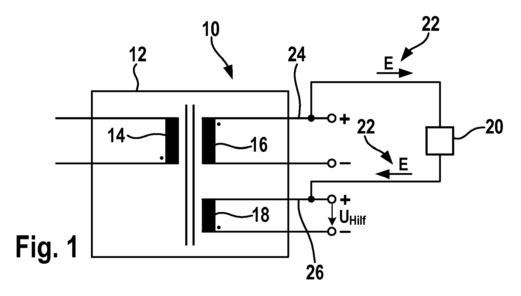
- Fig. 1 shows a block diagram of an embodiment of the present invention.
- the switched-mode power supply 10 comprises a transformer 12, which on the primary side comprises a primary winding 14 and, on the secondary side, a secondary winding 16 and an auxiliary winding 18.
- the switching power supply 10 includes a coupling unit 20, which allows a one-way power transmission 22 from a first terminal 24 of the secondary winding 16 to a first terminal 26 of the auxiliary winding 18.
- the first terminal 24 of the secondary winding 18 may be the connection for the positive potential for the tapped off at the secondary winding 16 voltage.
- the first terminal 26 of the auxiliary winding 18, the terminal of the positive potential of the tapped off at the terminals of the auxiliary winding 18 voltage can be.
- the switching power supply is operated, the maintenance of the auxiliary power supply is ensured by the coupling unit 20, especially when switching to standby mode or a strong reduction in the output power. If, in fact, the power consumed at the secondary winding is greatly reduced, the power consumption at the primary winding would also be greatly reduced by the retroactivity of the transformer, so that at the same time a strong reduction of the auxiliary voltage tapped off at the auxiliary winding would occur.
- the auxiliary voltage components of the switching power supply for example, microcontroller or control components, which should ensure proper operation of the switching power supply in the "stand-by" mode
- the correct functionality of these components could not be guaranteed become.
- the coupling unit 20 By the coupling unit 20, however, it is ensured that an energy transfer from the secondary winding 16 to the auxiliary winding 18 takes place, so that on the one hand, the secondary winding 16 is always (at least minimally) charged, so that a sudden drop in the power output can be "intercepted" within certain limits.
- the energy transfer from the secondary winding 16 to the auxiliary winding 18 via the coupling unit 20 also makes it possible for the auxiliary voltage U Hilf to be ensured even when the power output from the secondary winding 16 drops to a sufficient level.
- the main advantages of the invention are above all the simple circuit topology, a necessary for this small component cost and minimal additional costs. Furthermore, the redundancy of the auxiliary power supply is increased. The basic load on the secondary winding, which is necessary for proper operation of a controller used, can be dispensed with, with the result that additional cost optimization is achieved.
- Fig. 2 a schematic diagram of a further embodiment of the present invention is shown, wherein above all a detailed structure of the coupling unit 20 is shown. Opposite the Fig. 1 Rectifier diodes 28 are further provided to ensure a DC current in the circuits of the secondary and auxiliary windings 16 and 18, respectively. There are also Fig. 2 a schematic detail of a SNT 10 with a transformer again. In normal operation, the auxiliary voltage U Help is provided via the auxiliary winding 18th If the output power is abruptly reduced, the energy transfer from the primary winding 14 to the auxiliary winding 18 is also reduced via the direct coupling of the auxiliary winding 18 to the secondary winding 16. This leads to unwanted behavior of the controller and / or the microcontroller.
- Fig. 3 shows a flowchart of an embodiment of the present invention as a method 50. It is a transformer with primary side of a primary winding and secondary side of a secondary and an auxiliary winding is provided. If, in a first step 52, a power reduction across the secondary winding is reduced, in a second step 54, a transfer of energy from the secondary winding to the auxiliary winding and prevention of energy transfer from the auxiliary winding to the secondary winding can take place in order to keep the auxiliary voltage sufficiently high.
Landscapes
- Engineering & Computer Science (AREA)
- Power Engineering (AREA)
- Dc-Dc Converters (AREA)
Abstract
Die vorliegende Erfindung betrifft ein Schaltnetzteil (10) mit folgenden Merkmalen:
- einem Transformator(12), der primärseitig eine Primärwicklung (14) zur Leistungsaufnahme und sekundärseitig eine Sekundärwicklung (16) zur Leistungsabgabe sowie eine Hilfswicklung (18) zur Ausgabe einer Hilfsspannung (UHilf) aufweist; und
- einer Koppeleinheit (20), die ausgebildet ist, um die Sekundärwicklung (16) und die Hilfswicklung (18) derart zu koppeln, dass ein Energietransport (22) von der Sekundärwicklung (16) zur Hilfswicklung (18) ermöglicht und ein Energietransport von der Hilfswicklung (18) in die Sekundärwicklung (16) verhindert wird.
- having a transformer (12), the primary side a primary winding (14) for power and the secondary side a secondary winding (16) for the power output as well as an auxiliary winding (18) for outputting an auxiliary voltage (U Help); and
- A coupling unit (20) which is adapted to the secondary winding (16) and the auxiliary winding (18) to couple such that an energy transport (22) from the secondary winding (16) to the auxiliary winding (18) allows and energy transport from the Auxiliary winding (18) in the secondary winding (16) is prevented.
Description
Die vorliegende Erfindung bezieht sich auf ein Schaltnetzteil gemäß Anspruch 1 sowie ein Verfahren zum Betreiben eines Schaltnetzteils gemäß Anspruch 8.The present invention relates to a switching power supply according to
Schaltnetzteile (kurz SNT's), wie sie zum Beispiel in Ladegeräten eingesetzt werden, benötigen im Betrieb eine Hilfsspannung. Diese Hilfsspannung versorgt die Reglerkomponenten und gegebenenfalls einen Mikrocontroller.Switching power supplies (short SNT's), as used for example in chargers, require an auxiliary voltage during operation. This auxiliary voltage supplies the regulator components and possibly a microcontroller.
Die Hilfsspannungsversorgung in Schaltnetzteilen wird in der Regel über eine zusätzlich angebrachte Trafo-Wicklung bereitgestellt. Der Vorteil dieser separaten Wicklung besteht darin, dass bei einem ausgangsseitigen Kurzschluss die Hilfsspannungsversorgung nicht betroffen ist. Bei SNT's, die in einen Bereitschaftsmodus ("stand-by") versetzt oder mit stark reduzierter Ausgangsleistung betrieben werden können, wird eine zusätzliche Spannungsversorgung benötigt, da die Hilfsspannungswicklung nicht mehr genügend Energie bereitstellen kann. Dies ist jedoch mit hohen Kosten verbunden.The auxiliary power supply in switching power supplies is usually provided via an additionally mounted transformer winding. The advantage of this separate winding is that, in the case of an output-side short-circuit, the auxiliary voltage supply is not affected. SNTs that can be put into stand-by mode or run at greatly reduced output require an additional power supply as the auxiliary voltage winding can no longer provide enough power. However, this is associated with high costs.
Es ist daher die Aufgabe der vorliegenden Erfindung, eine kostengünstigere Möglichkeit zur zuverlässigen Bereitstellung einer ausreichend hohen Hilfsspannung zu schaffen.It is therefore the object of the present invention to provide a cost effective way to reliably provide a sufficiently high auxiliary voltage.
Diese Aufgabe wird durch ein Schaltnetzteil mit den Merkmalen des Anspruchs 1 sowie durch ein Verfahren zum Betreiben eines Schaltnetzteils mit den Schritten des Anspruchs 8 gelöst. Weitere Ausführungsformen der Erfindung ergeben sich aus den abhängigen Patentansprüchen.This object is achieved by a switching power supply with the features of
Die vorliegende Erfindung schafft ein Schaltnetzteil mit folgenden Merkmalen:
- einem Transformator, der primärseitig eine Primärwicklung zur Energieaufnahme und sekundärseitig eine Sekundärwicklung zur Energieabgabe sowie eine Hilfswicklung zur Ausgabe einer Hilfsspannung aufweist; und
- einer Koppeleinheit, die ausgebildet ist, um die Sekundärwicklung und die Hilfswicklung derart zu koppeln, dass ein Energietransport von der Sekundärwicklung zur Hilfswicklung ermöglicht wird und ein Energietransport von der Hilfswicklung in die Sekundärwicklung verhindert wird.
- a transformer having on the primary side a primary winding for absorbing energy and on the secondary side a secondary winding for discharging energy as well as an auxiliary winding for outputting an auxiliary voltage; and
- a coupling unit configured to couple the secondary winding and the auxiliary winding such that energy transfer from the secondary winding to the auxiliary winding is enabled and energy transfer from the auxiliary winding to the secondary winding is prevented.
Die vorliegende Erfindung basiert auf der Erkenntnis, dass eine einfache Möglichkeit zum sicheren und zuverlässigen Bereitstellen der Hilfsspannung durch eine Kopplung zwischen der Sekundärwicklung und der Hilfswicklung erreichbar ist, bei der lediglich ein Energiefluss von der Sekundärwicklung zur Hilfswicklung ermöglicht wird. Ein Energiefluss von der Hilfswicklung zur Sekundärwicklung wird dagegen unterbunden. Hierbei wird bei einem Absinken der Leistungsabgabe durch die Sekundärwicklung (z.B. einem ausgangsseitigen Kurzschluss) sichergestellt, dass durch die Energieübertragung in die Hilfswicklung noch eine ausreichend hohe Hilfsspannung ausgegeben werden kann. Durch diese, von der Sekundärwicklung an die Hilfswicklung abgegebene Mindestleistung bzw. -energie kann auch bewirkt werden, dass die Sekundärwicklung immer eine gewisse Restbelastung erfährt, so dass bei geeigneter Dimensionierung der Hilfswicklung des Transformators und der Koppeleinheit auch die ausreichende Höhe der Hilfsspannung sichergestellt ist.The present invention is based on the recognition that a simple possibility for reliable and reliable provision of the auxiliary voltage can be achieved by a coupling between the secondary winding and the auxiliary winding, in which only an energy flow from the secondary winding to the auxiliary winding is made possible. An energy flow from the auxiliary winding to the secondary winding, however, is prevented. In this case, when the power output drops through the secondary winding (eg an output-side short-circuit), it is ensured that a sufficiently high auxiliary voltage can still be output by the energy transmission into the auxiliary winding. By this, output from the secondary winding to the auxiliary winding minimum power or energy can also be effected that the secondary winding always experiences a certain residual load, so that with suitable dimensioning of the auxiliary winding of the transformer and the coupling unit and the sufficient amount of auxiliary voltage is ensured.
Der erfindungsgemäße Ansatz bietet den Vorteil, dass nunmehr durch eine sehr einfache Schaltungstopologie eine deutliche Verbesserung in der Robustheit der Bereitstellung einer ausreichend hohen Hilfsspannung möglich wird. Gegenüber Lösungen aus dem Stand der Technik führt dies zu kostengünstigeren Schaltnetzteilen. Weiterhin kann auch durch die Kopplung eine ansonsten erforderliche Grundlast in Form eines Mindestwiderstandes über die Anschlüsse der Sekundärwicklung entfallen. Im Betrieb des Schaltnetzteils führt das Entfallen eines solchen Mindestwiderstandes zu einer Verringerung der Verlustenergie und dadurch auch zu geringeren Betriebskosten wegen des geringeren Energiebedarfs des vorgeschlagenen Schaltnetzteils gegenüber herkömmlichen Schaltnetzteilen.The approach according to the invention offers the advantage that a clear improvement in the robustness of the provision of a sufficiently high auxiliary voltage is now possible by means of a very simple circuit topology. Compared to solutions from the prior art, this leads to less expensive switching power supplies. Furthermore, an otherwise required base load in the form of a minimum resistance via the terminals of the secondary winding can be omitted by the coupling. In operation of the switching power supply, the elimination of such a minimum resistance leads to a reduction of the energy loss and thereby also to lower operating costs because of the lower energy consumption of the proposed switching power supply over conventional switching power supplies.
Gemäß einer Ausführungsform der vorliegenden Erfindung umfasst die Koppeleinheit eine Diode. Dies bietet die Möglichkeit, durch ein einfaches schaltungstechnisches Bauelement eine Einweg-Energieübertragung von der Sekundärwicklung zur Hilfswicklung zu ermöglichen, wodurch sich das Schaltnetzteil gemäß dieser Ausführungsform sehr kostengünstig herstellen lässt.According to one embodiment of the present invention, the coupling unit comprises a diode. This offers the possibility of enabling a one-way energy transfer from the secondary winding to the auxiliary winding by means of a simple circuit-engineering component, as a result of which the switched-mode power supply can be produced very inexpensively according to this embodiment.
Günstig ist es auch, wenn die Diode derart gepolt ist, dass ihre Anode mit der Sekundärwicklung und ihre Kathode mit der Hilfswicklung gekoppelt ist. Insbesondere dann, wenn die an den Anschlüssen der Hilfswicklung (bezogen auf ein Massepotential) abgreifbare Spannung unter eine an den Anschlüssen der Sekundärwicklung (ebenfalls bezogen auf das Massepotential) abgreifbare Spannung absinkt, ermöglicht dies die einfache Implementierung der Koppeleinheit, welche die Energie nur in eine Richtung übertragen soll.It is also favorable if the diode is polarized such that its anode is coupled to the secondary winding and its cathode to the auxiliary winding. In particular, when the voltage which can be tapped off at the terminals of the auxiliary winding (relative to a ground potential) drops below a voltage which can be tapped off at the terminals of the secondary winding (likewise based on the ground potential), this allows the simple implementation of the coupling unit which only converts the energy into one To transfer direction.
In einer anderen Ausführungsform der vorliegenden Erfindung umfasst die Koppeleinheit einen diskreten Widerstand. Dies ermöglicht eine Begrenzung eines Stromflusses von der Sekundärwicklung zur Hilfswicklung, wodurch ein schaltungstechnisch einfacher Überlastschutz gegen eine zu große Energieübertragung von der Sekundärwicklung zur Hilfswicklung realisierbar ist.In another embodiment of the present invention, the coupling unit comprises a discrete resistor. This allows a limitation of a current flow from the secondary winding to the auxiliary winding, whereby a circuit technology simple overload protection against excessive energy transfer from the secondary winding to the auxiliary winding can be realized.
Auch kann gemäß einer weiteren Ausführungsform der vorliegenden Erfindung ein erster Anschluss der Koppeleinheit mit einem Anschluss für das positive Potential der Sekundärwicklung verbunden sein und ein zweiter Anschluss der Koppeleinheit mit einem Ausgangsanschluss für die Hilfsspannung der Hilfswicklung verbunden sein. Insbesondere dann, wenn die Hilfsspannung unter das Niveau der Spannung über die Anschlüsse der Sekundärwicklung sinkt, ermöglicht dies durch die Potentialdifferenz zwischen den beiden Anschlüssen die einfache Sicherstellung des Energieflusses von der Sekundärwicklung zur Hilfswicklung und unterstützt das Verhindern des Energie-Rückflusses von der Hilfswicklung zur Sekundärwicklung.Also, according to a further embodiment of the present invention, a first terminal of the coupling unit can be connected to a terminal for the positive potential of the secondary winding and a second terminal of the coupling unit to be connected to an output terminal for the auxiliary voltage of the auxiliary winding. In particular, when the auxiliary voltage decreases below the level of the voltage across the terminals of the secondary winding, this allows the potential difference between the two terminals to easily ensure the flow of energy from the secondary winding to the auxiliary winding and helps prevent the energy return from the auxiliary winding to the secondary winding ,
Weiterhin können auch gemäß einer anderen Ausführungsform die Anschlüsse der Sekundärwicklung über eine Kapazität verbunden sein und die Anschlüsse der Hilfswicklung über eine Kapazität verbunden sein. Dies ermöglicht eine Glättung der Ausgangsspannung der Sekundärwicklung als auch der von der Hilfswicklung ausgegebenen Hilfsspannung, wobei dann im Fall des Absinkens der Leistungsabnahme von der Sekundärwicklung lediglich ein Umladen der Kapazität zwischen den Anschlüssen der Sekundärwicklung in die Kapazität erfolgt, die zwischen den Anschlüssen der Hilfswicklung geschaltet ist. Somit erfolgt durch diese Umladung der Kapazitäten bzw. Kondensatoren eine Minimierung des Energieverlusts; dagegen würde durch Entladung diejenige Energie verloren gehen, die in der Kapazität gespeichert war, die zwischen die Anschlüsse der Sekundärwicklung geschaltet ist.Furthermore, according to another embodiment, the terminals of the secondary winding can be connected via a capacitor and the terminals of the auxiliary winding can be connected via a capacitor. This makes it possible to smooth the output voltage of the secondary winding as well as the auxiliary voltage output from the auxiliary winding, in which case the capacitance between the terminals of the secondary winding is only transferred into the capacitance connected between the terminals of the auxiliary winding in the event of a decrease in the output from the secondary winding is. Thus, this transhipment of the capacitors or capacitors minimizes the energy loss; on the other hand, discharge would lose the energy stored in the capacitance connected between the terminals of the secondary winding.
Auch kann in einer anderen günstigen Ausführungsform die Sekundärwicklung einen Anschluss aufweisen, der über ein Massepotential mit einem Anschluss der Hilfswicklung verbunden ist. Dies bietet die Möglichkeit einer schaltungstechnisch sehr einfachen Stromkreisbildung über das Massepotential, so dass die Koppeleinheit im Wesentlichen durch eine einzelne Leitungsverbindung (mit zum Beispiel in Serie geschalteten Bauelementen) zwischen der Sekundärwicklung und der Hilfswicklung möglich wird.Also, in another favorable embodiment, the secondary winding having a terminal which is connected via a ground potential to a terminal of the auxiliary winding. This offers the possibility of a circuitry very simple circuit over the ground potential, so that the coupling unit essentially by a single line connection (with, for example connected in series) between the secondary winding and the auxiliary winding is possible.
Gemäß einer anderen Ausführungsform der vorliegenden Erfindung ist ein Verfahren zum Betreiben eines Schaltnetzteils vorgesehen, wobei das Schaltnetzteil einen Transformator aufweist, der primärseitig eine Primärwicklung zur Energieaufnahme und sekundärseitig eine Sekundärwicklung zur Energieabgabe sowie eine Hilfswicklung zur Ausgabe einer Hilfsspannung umfasst, wobei das Verfahren folgende Schritte umfasst:
- Reduzieren der Energieabgabe über die Sekundärwicklung; und
- Übertragen von Energie von der Sekundärwicklung zur Hilfswicklung sowie Verhindern einer Energieübertragung von der Hilfswicklung zur Sekundärwicklung.
- Reducing the energy output via the secondary winding; and
- Transferring energy from the secondary winding to the auxiliary winding and preventing energy transfer from the auxiliary winding to the secondary winding.
Die Erfindung wird nachstehend anhand der beigefügten Zeichnungen beispielhaft näher erläutert. Es zeigen:
- Fig. 1
- ein Blockschaltbild eines Ausführungsbeispiels der vorliegenden Erfindung;
- Fig. 2
- eine schematische Schaltskizze eines weiteren Ausführungsbeispiels der vorliegenden Erfindung; und
- Fig. 3
- ein Ablaufdiagramm eines Ausführungsbeispiels der vorliegenden Erfindung.
- Fig. 1
- a block diagram of an embodiment of the present invention;
- Fig. 2
- a schematic circuit diagram of another embodiment of the present invention; and
- Fig. 3
- a flowchart of an embodiment of the present invention.
Gleiche oder ähnliche Elemente können in den nachfolgenden Figuren durch gleiche oder ähnliche Bezugszeichen versehen sein. Weiterhin sind eventuell angegebene Dimensionen und Maße nur exemplarisch, so dass die Erfindung nicht auf diese Dimensionen und Maße beschränkt ist. Ferner enthalten die Figuren der Zeichnungen, deren Beschreibung sowie die Ansprüche zahlreiche Merkmale in Kombination. Einem Fachmann ist dabei klar, dass diese Merkmale auch einzeln betrachtet werden oder sie zu weiteren, hier nicht explizit beschriebenen Kombinationen zusammengefasst werden können.The same or similar elements may be provided in the following figures by the same or similar reference numerals. Furthermore, any given dimensions and dimensions are exemplary only, so that the invention is not limited to these dimensions and dimensions. Furthermore, the figures of the Drawings, their description and the claims numerous features in combination. It is clear to a person skilled in the art that these features are also considered individually or that they can be combined to form further combinations not explicitly described here.
Wird nun das Schaltnetzteil betrieben, wird durch die Koppeleinheit 20 die Aufrechterhaltung der Hilfsspannungsversorgung vor allem beim Umschalten in den Bereitschaftsmodus oder einem starken Reduzieren der Ausgangsleistung sichergestellt. Wird nämlich die an der Sekundärwicklung abgegriffene Leistung stark reduziert, würde auch durch die Rückwirkung des Transformators die Leistungsaufnahme an der Primärwicklung stark reduziert, so dass zugleich auch eine starke Reduktion der an der Hilfswicklung abgreifbaren Hilfsspannung zu verzeichnen wäre. Werden jedoch mit der Hilfsspannung Komponenten des Schaltnetzteils (beispielsweise Mikrocontroller oder Regelkomponenten, die auch einen ordnungsgemäßen Betrieb des Schaltnetzteils im "Stand-by"-Modus sicherstellen sollen) betrieben, die auf eine minimale Hilfsspannung angewiesen sind, könnte die korrekte Funktionalität dieser Komponenten nicht gewährleistet werden. Durch die Koppeleinheit 20 wird dagegen sichergestellt, dass ein Energietransfer von der Sekundärwicklung 16 zur Hilfswicklung 18 erfolgt, so dass einerseits die Sekundärwicklung 16 stets (zumindest minimal) belastet wird, so dass ein plötzlicher Abfall der Leistungsabgabe in gewissen Grenzen "abgefangen" werden kann.Now, if the switching power supply is operated, the maintenance of the auxiliary power supply is ensured by the
Andererseits wird auch durch den Energietransfer von der Sekundärwicklung 16 zur Hilfswicklung 18 über die Koppeleinheit 20 ermöglicht, dass die Hilfsspannung UHilf auch bei einem Abfall der Leistungsabgabe von der Sekundärwicklung 16 noch in ausreichender Höhe sichergestellt werden kann. Durch die Verwendung einer sehr einfachen Schaltung als Koppeleinheit 20 werden zugleich eine sehr geringe Ausfallrate sowie geringe Realisierungskosten erzielt.On the other hand, the energy transfer from the secondary winding 16 to the auxiliary winding 18 via the
Die wesentlichen Vorteile der Erfindung sind vor allem die simple Schaltungstopologie, ein hierzu notwendiger geringer Bauteilaufwand und minimale Zusatzkosten. Des Weiteren wird die Redundanz der Hilfsspannungsversorgung erhöht. Die für einen einwandfreien Betrieb eines eingesetzten Reglers notwendige Grundlast an der Sekundärwicklung kann entfallen, womit eine zusätzliche Kostenoptimierung erzielt wird.The main advantages of the invention are above all the simple circuit topology, a necessary for this small component cost and minimal additional costs. Furthermore, the redundancy of the auxiliary power supply is increased. The basic load on the secondary winding, which is necessary for proper operation of a controller used, can be dispensed with, with the result that additional cost optimization is achieved.
In
Abhilfe schafft hier die gemäß diesem Ausführungsbeispiel vorgesehene Verbindung zwischen der Ausgangs- und der Hilfsspannung mit der Koppeleinheit 20, die in einer Serienschaltung aus einer Diode D und einem Widerstand R implementiert ist (wie dies auch in
- Sinkt die Hilfsspannung unter das Niveau der Ausgangsspannung, so wird der Pufferkondensator CH, der zwischen die Anschlüsse der Hilfswicklung 18 geschaltet ist, über die Diode D und den Widerstand R der Koppeleinheit 20 aufgeladen. Somit kann die Hilfsspannung nie kritische Minimalwerte annehmen und die Funktionstüchtigkeit des
SNT 10 beeinträchtigen. Der vorstehend genannte Energietransport kann dann in Form eines Stromflusses über die Diode D und den Widerstand R erfolgen. Dabei kann insbesondere eine einfache Umladung der Ladung des zur Spannungsglättung vorgesehenen Sekundärwicklungskondensators CS (der zwischen die Anschlüsse der Sekundärwicklung geschaltet ist) in den Hilfswicklungskondensator (oder Pufferkondensator) CH erfolgen, so dass durch die Umladung gegenüber einer Entladung ein Energieverlust minimiert werden kann. Der Hilfswicklungskondensator CH ist dabei ebenfalls zur Glättung der Hilfsspannung gegen Schwankungen der Energieübertragung des Transformators in die Hilfswicklung vorgesehen. Diese Umladung stellt dabei eine Belastung für den Ausgangs- oder Sekundärwicklungskreis dar, weswegen auf eine Grundlast RG zwischen den Anschlüssen der Sekundärwicklung verzichtet werden kann (was inFig. 2 durch einen durchgestrichenen Widerstand RG gekennzeichnet ist). Eine solche Grundlast ist gemäß dem Stand der Technik als Mindestwiderstand ausgebildet. Hierdurch wird mit dem vorgeschlagenen Ansatz eine weitere Kostenreduktion für den Betrieb des Schaltnetzteils möglich, da die Mindestverlustleistung und damit die Energieverluste (auch während des "Stand-by"-Modus) des Schaltnetzteils reduziert werden können. Da der Energietransport zwischen dem Ausgangskreis und der Hilfsspannungsversorgung stattfindet, wird der Wirkungsgrad der Anordnung somit zusätzlich verbessert. Durchdie gemeinsame Masseverbindung 30 zwischen dem zweiten Anschluss der Sekundärwicklung 16 und dem zweiten Anschluss der Hilfswicklung 18 wird auch ermöglicht, dass der Energietransport lediglich durch eine Leitung zwischen den erstenAnschlüssen 24 und 26 der Sekundär-und Hilfswicklung 16 bzw. 18 erfolgt. Hierdurch wird auch der schaltungstechnische Aufwand minimiert.
- If the auxiliary voltage drops below the level of the output voltage, the buffer capacitor C H connected between the terminals of the auxiliary winding 18 is charged via the diode D and the resistor R of the
coupling unit 20. Thus, the auxiliary voltage can never assume critical minimum values and impair the functionality of theSNT 10. The aforementioned energy transport can then take place in the form of a current flow via the diode D and the resistor R. In this case, in particular, a simple transhipment of the charge of the voltage smoothing provided secondary winding capacitor C S (which is connected between the terminals of the secondary winding) in the auxiliary winding capacitor (or buffer capacitor) C H done so that the transhipment relative to a discharge energy loss can be minimized. The auxiliary winding capacitor C H is also provided for smoothing the auxiliary voltage against fluctuations in the energy transfer of the transformer in the auxiliary winding. This transhipment represents a burden on the output or secondary winding circuit, which is why a basic load R G between the terminals of the secondary winding can be dispensed with (which is described in US PatFig. 2 is indicated by a crossed-out resistor R G ). Such a base load is formed according to the prior art as a minimum resistance. As a result, with the proposed approach, a further cost reduction for the operation of the switching power supply possible because the minimum power loss and thus the energy losses (even during the "stand-by" mode) of the switching power supply can be reduced. Since the energy transport between the output circuit and the auxiliary voltage supply takes place, the efficiency of the arrangement is thus additionally improved. Thecommon ground connection 30 between the second terminal of the secondary winding 16 and the second terminal of the auxiliary winding 18 also enables the energy to be transported only through a line between thefirst terminals auxiliary windings
Claims (8)
Applications Claiming Priority (1)
| Application Number | Priority Date | Filing Date | Title |
|---|---|---|---|
| DE102007062728A DE102007062728A1 (en) | 2007-12-27 | 2007-12-27 | Switched mode power supply and method for operating a switched mode power supply |
Publications (2)
| Publication Number | Publication Date |
|---|---|
| EP2075902A2 true EP2075902A2 (en) | 2009-07-01 |
| EP2075902A3 EP2075902A3 (en) | 2014-09-24 |
Family
ID=40456302
Family Applications (1)
| Application Number | Title | Priority Date | Filing Date |
|---|---|---|---|
| EP08105739.0A Withdrawn EP2075902A3 (en) | 2007-12-27 | 2008-11-06 | Switching power supply and method for operating a switching power supply |
Country Status (2)
| Country | Link |
|---|---|
| EP (1) | EP2075902A3 (en) |
| DE (1) | DE102007062728A1 (en) |
Family Cites Families (5)
| Publication number | Priority date | Publication date | Assignee | Title |
|---|---|---|---|---|
| FR2537744A1 (en) * | 1982-12-10 | 1984-06-15 | Radiotechnique | METHOD FOR MODIFYING IN DIFFERENT VARIOUS VOLTAGE REPORTS OF A POWER SUPPLY, AND TWO-STATE CUTTING POWER SUPPLY |
| IT1231052B (en) * | 1989-09-27 | 1991-11-12 | Bull Hn Information Syst | SWITCHING POWER SUPPLY WITH MULTIPLE OUTPUTS, ADJUSTING AN OUTPUT VOLTAGE AND LOAD COMPENSATION. |
| KR920000347Y1 (en) * | 1989-12-29 | 1992-01-15 | 삼성전자 주식회사 | SMPS Control Circuit with Two Outputs |
| DE69942973D1 (en) * | 1999-06-01 | 2011-01-05 | Semiconductor Components Ind | Pulse width modulation control |
| CN101164220B (en) * | 2005-04-21 | 2012-05-23 | 半导体元件工业有限责任公司 | Power source control method and structure thereof |
-
2007
- 2007-12-27 DE DE102007062728A patent/DE102007062728A1/en not_active Withdrawn
-
2008
- 2008-11-06 EP EP08105739.0A patent/EP2075902A3/en not_active Withdrawn
Also Published As
| Publication number | Publication date |
|---|---|
| EP2075902A3 (en) | 2014-09-24 |
| DE102007062728A1 (en) | 2009-07-02 |
Similar Documents
| Publication | Publication Date | Title |
|---|---|---|
| EP0911942B1 (en) | Method and circuit arrangement for momentarily maintaining an output voltage by means of an autarky capacitor in case of failure of the input voltage | |
| EP0525898A2 (en) | Circuit arrangement with a switching power supply | |
| DE69012834T2 (en) | CHARGING DEVICE FOR ELECTRIC ENERGY STORAGE WITH CHARGE CONTROL MEANS. | |
| DE102005014285A1 (en) | Apparatus and method for charge equalization of arranged in series individual cells of an energy storage | |
| DE202010017938U1 (en) | An apparatus for implementing a power converter input terminal voltage discharge circuit | |
| EP2812980B1 (en) | Power supply | |
| DE112008003996T5 (en) | driver unit | |
| DE102015110658A1 (en) | A POWER SUPPLY USED IN A DEVICE HAVING A HIGH-TEMPERATURE CHARACTERISTICS | |
| DE10007546A1 (en) | DC to DC converter, e.g. for electric vehicle without potential isolation measures voltage across capacitor and voltage at output, switches off second switch if voltage difference is equalled or exceeded | |
| EP2138015B1 (en) | Circuit configuration for generating an auxiliary voltage and for operating at least one discharge lamp | |
| DE10254408A1 (en) | Charge pumped DC signal bias supply | |
| DE60207724T2 (en) | SWITCHING PART WITH DAMPING CIRCUIT | |
| EP1453177B1 (en) | Dc/dc converter circuit | |
| DE10213477A1 (en) | Control device for DC converters | |
| DE19602121C1 (en) | Current limiting circuit, e.g. for power supply or DC-DC converter | |
| DE19901196A1 (en) | Method and device for power supply | |
| EP2609662B1 (en) | Control circuit for an auxiliary power supply unit, and power supply unit arrangement | |
| DE102009030319A1 (en) | Supply energy arrangement and method for providing a supply energy | |
| DE10232416B4 (en) | Circuit arrangement and method for stabilizing a supply voltage | |
| EP1825123A1 (en) | Electrical circuit for controlling a piezoelectric element, particularly of a fuel injection system of a motor vehicle | |
| DE102007062728A1 (en) | Switched mode power supply and method for operating a switched mode power supply | |
| EP0357060A2 (en) | Overvoltage protection device for an electronic circuit | |
| DE19548724A1 (en) | Method for protecting a switching regulator and arrangement and application | |
| EP0570704B1 (en) | Flyback converter | |
| DE3036092A1 (en) | BATTERY CHARGING SYSTEM |
Legal Events
| Date | Code | Title | Description |
|---|---|---|---|
| PUAI | Public reference made under article 153(3) epc to a published international application that has entered the european phase |
Free format text: ORIGINAL CODE: 0009012 |
|
| AK | Designated contracting states |
Kind code of ref document: A2 Designated state(s): AT BE BG CH CY CZ DE DK EE ES FI FR GB GR HR HU IE IS IT LI LT LU LV MC MT NL NO PL PT RO SE SI SK TR |
|
| AX | Request for extension of the european patent |
Extension state: AL BA MK RS |
|
| PUAL | Search report despatched |
Free format text: ORIGINAL CODE: 0009013 |
|
| AK | Designated contracting states |
Kind code of ref document: A3 Designated state(s): AT BE BG CH CY CZ DE DK EE ES FI FR GB GR HR HU IE IS IT LI LT LU LV MC MT NL NO PL PT RO SE SI SK TR |
|
| AX | Request for extension of the european patent |
Extension state: AL BA MK RS |
|
| RIC1 | Information provided on ipc code assigned before grant |
Ipc: H02M 1/00 20070101ALI20140818BHEP Ipc: H02M 3/335 20060101AFI20140818BHEP |
|
| 17P | Request for examination filed |
Effective date: 20150324 |
|
| RBV | Designated contracting states (corrected) |
Designated state(s): AT BE BG CH CY CZ DE DK EE ES FI FR GB GR HR HU IE IS IT LI LT LU LV MC MT NL NO PL PT RO SE SI SK TR |
|
| AKX | Designation fees paid |
Designated state(s): DE FR GB IT |
|
| AXX | Extension fees paid |
Extension state: BA Extension state: RS Extension state: MK Extension state: AL |
|
| 17Q | First examination report despatched |
Effective date: 20150924 |
|
| STAA | Information on the status of an ep patent application or granted ep patent |
Free format text: STATUS: THE APPLICATION IS DEEMED TO BE WITHDRAWN |
|
| 18D | Application deemed to be withdrawn |
Effective date: 20160405 |