EP2076011A1 - Verfahren zur Erzeugung eines Dithering-Musters und entsprechendes Dithering-Muster - Google Patents
Verfahren zur Erzeugung eines Dithering-Musters und entsprechendes Dithering-Muster Download PDFInfo
- Publication number
- EP2076011A1 EP2076011A1 EP07301682A EP07301682A EP2076011A1 EP 2076011 A1 EP2076011 A1 EP 2076011A1 EP 07301682 A EP07301682 A EP 07301682A EP 07301682 A EP07301682 A EP 07301682A EP 2076011 A1 EP2076011 A1 EP 2076011A1
- Authority
- EP
- European Patent Office
- Prior art keywords
- bit
- dithering
- values
- value
- block
- Prior art date
- Legal status (The legal status is an assumption and is not a legal conclusion. Google has not performed a legal analysis and makes no representation as to the accuracy of the status listed.)
- Withdrawn
Links
Images
Classifications
-
- H—ELECTRICITY
- H04—ELECTRIC COMMUNICATION TECHNIQUE
- H04N—PICTORIAL COMMUNICATION, e.g. TELEVISION
- H04N1/00—Scanning, transmission or reproduction of documents or the like, e.g. facsimile transmission; Details thereof
- H04N1/40—Picture signal circuits
- H04N1/405—Halftoning, i.e. converting the picture signal of a continuous-tone original into a corresponding signal showing only two levels
- H04N1/4051—Halftoning, i.e. converting the picture signal of a continuous-tone original into a corresponding signal showing only two levels producing a dispersed dots halftone pattern, the dots having substantially the same size
-
- G—PHYSICS
- G09—EDUCATION; CRYPTOGRAPHY; DISPLAY; ADVERTISING; SEALS
- G09G—ARRANGEMENTS OR CIRCUITS FOR CONTROL OF INDICATING DEVICES USING STATIC MEANS TO PRESENT VARIABLE INFORMATION
- G09G3/00—Control arrangements or circuits, of interest only in connection with visual indicators other than cathode-ray tubes
- G09G3/20—Control arrangements or circuits, of interest only in connection with visual indicators other than cathode-ray tubes for presentation of an assembly of a number of characters, e.g. a page, by composing the assembly by combination of individual elements arranged in a matrix no fixed position being assigned to or needed to be assigned to the individual characters or partial characters
- G09G3/2007—Display of intermediate tones
- G09G3/2044—Display of intermediate tones using dithering
- G09G3/2051—Display of intermediate tones using dithering with use of a spatial dither pattern
- G09G3/2055—Display of intermediate tones using dithering with use of a spatial dither pattern the pattern being varied in time
-
- G—PHYSICS
- G09—EDUCATION; CRYPTOGRAPHY; DISPLAY; ADVERTISING; SEALS
- G09G—ARRANGEMENTS OR CIRCUITS FOR CONTROL OF INDICATING DEVICES USING STATIC MEANS TO PRESENT VARIABLE INFORMATION
- G09G3/00—Control arrangements or circuits, of interest only in connection with visual indicators other than cathode-ray tubes
- G09G3/20—Control arrangements or circuits, of interest only in connection with visual indicators other than cathode-ray tubes for presentation of an assembly of a number of characters, e.g. a page, by composing the assembly by combination of individual elements arranged in a matrix no fixed position being assigned to or needed to be assigned to the individual characters or partial characters
- G09G3/22—Control arrangements or circuits, of interest only in connection with visual indicators other than cathode-ray tubes for presentation of an assembly of a number of characters, e.g. a page, by composing the assembly by combination of individual elements arranged in a matrix no fixed position being assigned to or needed to be assigned to the individual characters or partial characters using controlled light sources
- G09G3/28—Control arrangements or circuits, of interest only in connection with visual indicators other than cathode-ray tubes for presentation of an assembly of a number of characters, e.g. a page, by composing the assembly by combination of individual elements arranged in a matrix no fixed position being assigned to or needed to be assigned to the individual characters or partial characters using controlled light sources using luminous gas-discharge panels, e.g. plasma panels
Definitions
- the invention relates to a method for generating a dithering pattern to be applied to data of a video picture to improve its quality for example when displayed on a matrix displays like plasma display panels (PDP) or other devices using pulse width modulation.
- PDP plasma display panels
- a PDP Pulsma Display Panel
- a PDP controls the video levels by modulating the number of light pulses per frame. These light pulses are also called sustain pulses. This time-modulation of the light pulses is then integrated by the eye over a period corresponding to the eye time response. Since the video level is portrayed by the number of light pulses occurring at a given frequency, a higher video level means more light pulses. For this reason, this kind of modulation is also known as PWM for Pulse Width Modulation.
- This PWM is responsible for one of the PDP image quality problems: the poor grey scale portrayal quality, especially in the darker regions of the picture. This is due to the fact that displayed luminance is linear to the number of pulses, but the eye response and sensitivity to noise is not linear. In darker areas the eye is more sensitive than in brighter areas. This means that even though modern PDPs can display ca. 255 discrete video levels, a quantization error is more noticeable in the darker areas.
- a PDP uses PWM (pulse width modulation) to generate the different video levels. Contrarily to CRTs where luminance is approximately quadratic to applied cathode voltage, luminance is linear to the number of sustain pulses. Therefore an approximately digital quadratic gamma function has to be applied to video before the PWM.
- PWM pulse width modulation
- Dithering is a known technique for avoiding losing amplitude resolution bits due to truncation.
- this technique only works if the required resolution is available before the truncation step. Usually this is the case in most applications, since the video data after a gamma operation used for pre-correction of the video signal has 16-bit resolution. Dithering can bring back as many bits as those lost by truncation in principle.
- a 1 bit-dithering corresponds to multiply the number of available output levels by 2
- a 2 bit-dithering corresponds to multiply the number of available output levels by 4
- a 3 bit-dithering corresponds to multiply the number of available output levels by 8.
- Dithering is applied to video data by using a dithering pattern.
- the values of this dithering pattern are added to the video data after the gamma operation and the resulting video data are then truncated (truncation step).
- the current dithering techniques give good results in terms of quantization error but introduce a dithering noise in the displayed pictures (like the error diffusion technique) or suffer from the dithering pattern visibility.
- the invention is aimed at alleviating the drawbacks of the prior art.
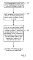
- the present invention concerns a method for generating at least one part of a dithering pattern, this part comprising 2 n dithering values each having n bits, wherein each bit value of the dithering values of the part is computed independently of the other bit values and in that, the n th bit of a dithering value being the least significant bit of said dithering value, the i th bit of the dithering values of the part is computed by the steps of:
- the first bit value is equal to the value of the decision bit and the second bit value is equal to a value different from the decision bit.
- the second bit value is equal to the value of the decision bit and the first bit value is equal to a value different from the decision bit.
- the decision bit associated to each block can be determined randomly. In a variant, it is a deterministic bit. In this variant, the decision bit associated to the blocks of the part changes alternatively between two values at each row and/or column of blocks of the part. It is also possible to change this decision bit at each video frame.
- the dithering pattern resulting from this method comprises 2 n different dithering values having each n bits and these values are distributed randomly over the whole pattern. Consequently, the invention concerns also a dithering pattern comprising 2 n dithering values having each n bits wherein the 2 n dithering values are different and distributed randomly over the whole pattern.
- the dithering pattern is generated part by part, each part comprising 2 8 dithering values and each dithering value being intended to be added to a pixel value (eventually after application of a gamma function) of an image.
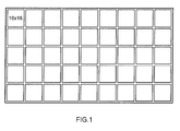
- This generation is illustrated by figure 1 where a dithering pattern comprising 144x80 dithering values is generated part by part, each part comprising 16x16 adjacent dithering values.
- the dithering pattern comprises 45 parts of 16x16 dithering values.
- the dithering pattern comprises parts, each part comprising blocks of dithering values and each block comprising sub-blocks of dithering values.
- the dithering pattern and the parts or blocks of it have a rectangular or square shape but they can have other shapes. These shapes have been adopted to simplify the drawings and the explanations.
- the present invention proposes a method for generating at least one part of the dithering pattern.
- the part to be generated comprises 2 n dithering values each having n bits.
- each bit value of the dithering values of the part is computed independently of the other bit values.
- the i th bit of the dithering values of the part is computed by the steps shown at figure 2 . It can be noted that the n th bit of a dithering value designates the least significant bit of the dithering value and that the 1 st bit of a dithering value designates the most significant bit of the dithering value.
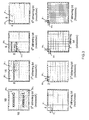
- bit values can be computed one after the other in the descending order of the parameter i as illustrated by Figure 3 , in the ascending order of the parameter i or in a different order. They can also be computed in parallel. It is possible because each bit value of a dithering value is computed independently of the other bit values of the dithering value.
- the method comprises the following steps:
- the decision bit can be random or deterministic as it will be described later.
- Figure 3 illustrates the generation of a part of a dithering pattern comprising 16x16 adjacent dithering values, each value of the dithering pattern being a 8-bit value.
- the number of values in the part is linked to the number of bits of the dithering values to be generated.
- the dithering pattern is split into parts of 2 n values to generate n-bit dithering values.
- the 8 th bit of the dithering values of the part of dithering pattern (which is identical to a block for this bit) is computed by splitting the part into first and second separated sub-blocks B0 8 and B1 8 of 8x16 values, allocating a first bit value to the i th bit of the dithering values of the first sub-block B0 8 and allocating a second bit value to the i th bit of the dithering values of the second sub-block B1 8 , the first and second bit values being different and depending on a decision bit associated to the block.
- the bit value 0 is allocated to the 8 th bit of the dithering values of the sub-block B0 8 and the bit value 1 is allocated to the 8 th bit of the dithering values of the sub-block B1 8 .
- the 7 th bit of the dithering values of the part of dithering pattern is computed by splitting this part into 2 separated blocks comprising 8x16 values and then splitting these separated (upper block and lower block) blocks into first and second separated sub-blocks comprising 8x8 values.
- a first bit value is allocated to the 7 th bit of the dithering values of the first sub-block of each block and a second bit value is allocated to the 7 th bit of the dithering values of the second sub-block of each block, the first and second bit values being different and depending on a decision bit associated to the considered block.
- the bit value 0 is allocated to the 7 th bit of the dithering values of a sub-block B0 7 and the bit value 1 is allocated to the 7 th bit of the dithering values of a sub-block B1 7 .
- the 6 th bit of the dithering values of the part of dithering pattern is computed by splitting this part into 4 separated blocks comprising 8x8 values and then splitting these separated blocks into first and second separated sub-blocks comprising 4x8 values.
- a first bit value is allocated to the 6 th bit of the dithering values of the first sub-block of each block and a second bit value is allocated to the 6 th bit of the dithering values of the second sub-block of each block, the first and second bit values being different and depending on a decision bit associated to the considered block.
- the 5 th bit of the dithering values of the part of dithering pattern is computed by splitting this part into 8 separated blocks comprising 4x8 values and then splitting these separated blocks into first and second separated sub-blocks comprising 4x4 values.
- a first bit value is allocated to the 5 th bit of the dithering values of the first sub-block of each block and a second bit value is allocated to the 5 th bit of the dithering values of the second sub-block of each block, the first and second bit values being different and depending on a decision bit associated to the considered block.
- the bit value 0 is allocated to the 5 th bit of the dithering values of a sub-block B0 5 and the bit value 1 is allocated to the 5 th bit of the dithering values of a sub-block B1 5 .
- the 4 th bit of the dithering values of the part of dithering pattern is computed by splitting this part into 16 separated blocks comprising 4x4 values and then splitting these separated blocks into first and second separated sub-blocks comprising 2x4 values.
- a first bit value is allocated to the 4 th bit of the dithering values of the first sub-block of each block and a second bit value is allocated to the 4 th bit of the dithering values of the second sub-block of each block, the first and second bit values being different and depending on a decision bit associated to the considered block.
- the bit value 0 is allocated to the 4 th bit of the dithering values of a sub-block B0 4 and the bit value 1 is allocated to the 4 th bit of the dithering values of a sub-block B1 4 .
- the 3 rd bit of the dithering values of the part of dithering pattern is computed by splitting this part into 16 separated blocks comprising 2x4 values and then splitting these separated blocks into first and second separated sub-blocks comprising 2x2 values.
- a first bit value is allocated to the 3 rd bit of the dithering values of the first sub-block of each block and a second bit value is allocated to the 3 rd bit of the dithering values of the second sub-block of each block, the first and second bit values being different and depending on a decision bit associated to the considered block.
- the bit value 0 is allocated to the 3 rd bit of the dithering values of a sub-block B0 3 and the bit value 1 is allocated to the 3 rd bit of the dithering values of a sub-block B1 3 .
- the 2 nd bit of the dithering values of the part of dithering pattern is computed by splitting this part into 32 separated blocks comprising 2x2 values and then splitting these separated blocks into first and second separated sub-blocks comprising 1x2 values.
- a first bit value is allocated to the 2 nd bit of the dithering values of the first sub-block of each block and a second bit value is allocated to the 2 nd bit of the dithering values of the second sub-block of each block, the first and second bit values being different and depending on a decision bit associated to the considered block.
- the bit value 0 is allocated to the 2 nd bit of the dithering values of a sub-block B0 2 and the bit value 1 is allocated to the 2 nd bit of the dithering values of a sub-block B1 2.
- the 1 st bit of the dithering values of the part of dithering pattern is computed by splitting this part into 32 separated blocks comprising 1x2 values and then splitting these separated blocks into first and second separated sub-blocks comprising only one value.
- a first bit value is allocated to the 1 st bit of the dithering values of the first sub-block of each block and a second bit value is allocated to the 1 st bit of the dithering values of the second sub-block of each block, the first and second bit values being different and depending on a decision bit associated to the considered block.
- the bit value 0 is allocated to the 1 st bit of the dithering values of a sub-block B0 1 and the bit value 1 is allocated to the 1 st bit of the dithering values of a sub-block B1 1 .
- a decision bit is associated to each block.
- This decision bit can be defined randomly for each block. In a variant, it can be predetermined for a first row or column of blocks and then changed at each next row or column of blocks. For example, this decision bit is 1 for the even rows or columns of blocks and 0 for the odd row or column of blocks. In another variant, it can change at each video frame. For example, this decision bit is 1 for the even rows or columns of blocks and 0 for the odd row or column of blocks in the even video frames and this decision bit is 0 for the even rows or columns of blocks and 1 for the odd row or column of blocks in the odd video frames.
- Frame 1 180 52 148 20 252 124 220 92 242 114 210 82 186 58 218 90 116 244 84 212 60 188 28 156 50 178 18 146 122 250 26 154 196 68 164 36 204 76 236 108 130 2 226 98 202 74 234 106 4 132 100 228 12 140 44 172 66 194 34 162 10 138 42 170 240 112 144 16 232 104 136 8 190 62 158 30 166 38 198 70 48 176 80 208 40 168 72 200 126 254 94 222 102 230 6 134 192 64 224 96 152 24 248 120 142 14 238 110 214 86 182 54 0 128 32 160 88 216 56 184 78 206 46 174 22 150 118 246 229 101 133 5 189 61 221 93 227 99 195 67 235
- the energy is distributed over the whole dithering pattern because the pattern comprises different values (256 different values for a 16x16 pattern dithering) and because these values are randomly distributed over the whole pattern.
- the values of the dithering pattern are used as follows : once the dithering pattern is defined, it is added pixel by pixel to the video levels, the resulting video levels being then truncated.
- This dithering operation can be used by example for a linear display device; in this case, the dithering values are added pixel by pixel to the video levels after gammatization.
- the invention can be used in particular in Patent Display Panels (PDPs).
- PDPs Patent Display Panels
- use of the invention is also appropriate for matrix displays where the light emission/generation is also controlled with small pulses, i.e. where the PWM principle is used for controlling brightness.
- the invention can also be used in a printing device.
Landscapes
- Engineering & Computer Science (AREA)
- Multimedia (AREA)
- Signal Processing (AREA)
- Controls And Circuits For Display Device (AREA)
Priority Applications (1)
| Application Number | Priority Date | Filing Date | Title |
|---|---|---|---|
| EP07301682A EP2076011A1 (de) | 2007-12-17 | 2007-12-17 | Verfahren zur Erzeugung eines Dithering-Musters und entsprechendes Dithering-Muster |
Applications Claiming Priority (1)
| Application Number | Priority Date | Filing Date | Title |
|---|---|---|---|
| EP07301682A EP2076011A1 (de) | 2007-12-17 | 2007-12-17 | Verfahren zur Erzeugung eines Dithering-Musters und entsprechendes Dithering-Muster |
Publications (1)
| Publication Number | Publication Date |
|---|---|
| EP2076011A1 true EP2076011A1 (de) | 2009-07-01 |
Family
ID=39410066
Family Applications (1)
| Application Number | Title | Priority Date | Filing Date |
|---|---|---|---|
| EP07301682A Withdrawn EP2076011A1 (de) | 2007-12-17 | 2007-12-17 | Verfahren zur Erzeugung eines Dithering-Musters und entsprechendes Dithering-Muster |
Country Status (1)
| Country | Link |
|---|---|
| EP (1) | EP2076011A1 (de) |
Citations (3)
| Publication number | Priority date | Publication date | Assignee | Title |
|---|---|---|---|---|
| EP0721278A2 (de) * | 1994-12-27 | 1996-07-10 | Dainippon Screen Mfg. Co., Ltd. | Verfahren zur Herstellung einer Schwellenmatrix sowie Verfahren und Vorrichtung zur Erzeugung eines halbtongerasterten Bildes |
| EP0836317A2 (de) * | 1996-10-10 | 1998-04-15 | Hewlett-Packard Company | Halbtonrasterungszittern |
| US20050286084A1 (en) * | 2004-06-14 | 2005-12-29 | Oce-Technologies B.V. | Method for generating a dither mask |
-
2007
- 2007-12-17 EP EP07301682A patent/EP2076011A1/de not_active Withdrawn
Patent Citations (3)
| Publication number | Priority date | Publication date | Assignee | Title |
|---|---|---|---|---|
| EP0721278A2 (de) * | 1994-12-27 | 1996-07-10 | Dainippon Screen Mfg. Co., Ltd. | Verfahren zur Herstellung einer Schwellenmatrix sowie Verfahren und Vorrichtung zur Erzeugung eines halbtongerasterten Bildes |
| EP0836317A2 (de) * | 1996-10-10 | 1998-04-15 | Hewlett-Packard Company | Halbtonrasterungszittern |
| US20050286084A1 (en) * | 2004-06-14 | 2005-12-29 | Oce-Technologies B.V. | Method for generating a dither mask |
Similar Documents
| Publication | Publication Date | Title |
|---|---|---|
| US6417824B1 (en) | Method of driving plasma display panel | |
| KR100499102B1 (ko) | 플라즈마 디스플레이 패널의 구동장치 및 구동방법 | |
| US6175194B1 (en) | Method for driving a plasma display panel | |
| EP1356443B1 (de) | Verfahren und vorrichtung zur steuerung einer anzeigeeinrichtung | |
| EP1536400B1 (de) | Verfahren zur Verarbeitung eines Grautons in einer Plamaanzeigetafel und dieses benutzendes Gerät | |
| EP1548696B1 (de) | Verfahren und Vorrichtung zur Ansteuerung einer Plasmaanzeige | |
| US7256794B2 (en) | Method and apparatus for processing video data of display device | |
| KR20040035753A (ko) | 플라즈마 디스플레이 패널과 같은 디스플레이 디바이스상에 비디오 영상을 디스플레이하는 방법 | |
| US6727913B2 (en) | Method and device for displaying images on a matrix display device | |
| KR100465547B1 (ko) | 플라즈마 디스플레이패널의 구동방법 및 플라즈마디스플레이 장치 | |
| KR100679098B1 (ko) | 플라즈마 디스플레이 패널의 위치별 게인 조정방법 및 장치 | |
| KR100570614B1 (ko) | 고부하 화면의 계조 표현 방법 및 그 방법을 사용한플라즈마 디스플레이 패널 구동 장치 | |
| EP1587053A2 (de) | Plasma-Anzeigegerät und Bildverarbeitungsverfahren dafür | |
| EP1638067A1 (de) | Verfahren und Vorrichtung zur Erzeugung von Teilfeldsteuerworten | |
| EP1630772A1 (de) | Verfahren und Vorrichtung zum Halbtonzittern | |
| US20050174304A1 (en) | Method of driving display panel | |
| KR20070035885A (ko) | 플라즈마 디스플레이 장치의 화상처리 방법 | |
| EP1995712A1 (de) | Verfahren zur Anwendung von Dithering für Videodaten und Anzeigevorrichtung mit diesem Verfahren | |
| US20050093775A1 (en) | Method of driving a plasma display panel | |
| KR100738816B1 (ko) | 플라즈마 디스플레이 패널의 화상처리 장치 및 화상처리방법 | |
| JP5224493B2 (ja) | 複数のピクセルから成るビデオ画像の処理方法および複数のピクセルから成るビデオ画像の処理装置 | |
| KR20050101442A (ko) | 플라즈마 디스플레이 패널의 화상 처리 장치 | |
| KR100599659B1 (ko) | 플라즈마 표시 장치 및 그 화상 처리 방법 | |
| US20070159469A1 (en) | Method and apparatus for processing video pictures, in particular for large area flicker effect reduction | |
| EP1679679A1 (de) | Verfahren und Vorrichtung zur Bearbeitung von Videobildern, im Besonderen zur Verminderung von großflächigen Flimmereffekten und Falschkontureffekten |
Legal Events
| Date | Code | Title | Description |
|---|---|---|---|
| PUAI | Public reference made under article 153(3) epc to a published international application that has entered the european phase |
Free format text: ORIGINAL CODE: 0009012 |
|
| AK | Designated contracting states |
Kind code of ref document: A1 Designated state(s): AT BE BG CH CY CZ DE DK EE ES FI FR GB GR HU IE IS IT LI LT LU LV MC MT NL PL PT RO SE SI SK TR |
|
| AX | Request for extension of the european patent |
Extension state: AL BA HR MK RS |
|
| AKX | Designation fees paid | ||
| REG | Reference to a national code |
Ref country code: DE Ref legal event code: 8566 |
|
| STAA | Information on the status of an ep patent application or granted ep patent |
Free format text: STATUS: THE APPLICATION IS DEEMED TO BE WITHDRAWN |
|
| 18D | Application deemed to be withdrawn |
Effective date: 20100105 |