EP2076336B1 - Fluidversorgungsvorrichtung für eine spritzanlage - Google Patents
Fluidversorgungsvorrichtung für eine spritzanlage Download PDFInfo
- Publication number
- EP2076336B1 EP2076336B1 EP07819973A EP07819973A EP2076336B1 EP 2076336 B1 EP2076336 B1 EP 2076336B1 EP 07819973 A EP07819973 A EP 07819973A EP 07819973 A EP07819973 A EP 07819973A EP 2076336 B1 EP2076336 B1 EP 2076336B1
- Authority
- EP
- European Patent Office
- Prior art keywords
- valves
- lines
- colour
- fluid supply
- supply device
- Prior art date
- Legal status (The legal status is an assumption and is not a legal conclusion. Google has not performed a legal analysis and makes no representation as to the accuracy of the status listed.)
- Not-in-force
Links
- 239000012530 fluid Substances 0.000 title claims abstract description 48
- 238000005507 spraying Methods 0.000 title claims abstract description 16
- 239000012459 cleaning agent Substances 0.000 claims abstract description 17
- 239000003086 colorant Substances 0.000 claims description 24
- 239000004922 lacquer Substances 0.000 claims description 16
- 238000004140 cleaning Methods 0.000 claims description 14
- 238000000034 method Methods 0.000 claims description 6
- 239000003795 chemical substances by application Substances 0.000 claims description 5
- 239000011248 coating agent Substances 0.000 claims description 4
- 238000000576 coating method Methods 0.000 claims description 4
- 239000003973 paint Substances 0.000 abstract description 86
- 239000007921 spray Substances 0.000 description 15
- 239000003599 detergent Substances 0.000 description 11
- 239000004848 polyfunctional curative Substances 0.000 description 11
- 239000002966 varnish Substances 0.000 description 6
- 239000007788 liquid Substances 0.000 description 5
- 239000002904 solvent Substances 0.000 description 5
- 238000009434 installation Methods 0.000 description 4
- 238000010926 purge Methods 0.000 description 4
- 238000010422 painting Methods 0.000 description 3
- 238000011010 flushing procedure Methods 0.000 description 2
- 241001071864 Lethrinus laticaudis Species 0.000 description 1
- 238000007599 discharging Methods 0.000 description 1
- 230000009977 dual effect Effects 0.000 description 1
- 238000005516 engineering process Methods 0.000 description 1
- 238000004519 manufacturing process Methods 0.000 description 1
- 239000000203 mixture Substances 0.000 description 1
- 230000010349 pulsation Effects 0.000 description 1
- 238000004381 surface treatment Methods 0.000 description 1
- 238000011144 upstream manufacturing Methods 0.000 description 1
Images



Classifications
-
- B—PERFORMING OPERATIONS; TRANSPORTING
- B05—SPRAYING OR ATOMISING IN GENERAL; APPLYING FLUENT MATERIALS TO SURFACES, IN GENERAL
- B05B—SPRAYING APPARATUS; ATOMISING APPARATUS; NOZZLES
- B05B12/00—Arrangements for controlling delivery; Arrangements for controlling the spray area
- B05B12/14—Arrangements for controlling delivery; Arrangements for controlling the spray area for supplying a selected one of a plurality of liquids or other fluent materials or several in selected proportions to a spray apparatus, e.g. to a single spray outlet
- B05B12/1418—Arrangements for controlling delivery; Arrangements for controlling the spray area for supplying a selected one of a plurality of liquids or other fluent materials or several in selected proportions to a spray apparatus, e.g. to a single spray outlet for supplying several liquids or other fluent materials in selected proportions to a single spray outlet
-
- B—PERFORMING OPERATIONS; TRANSPORTING
- B05—SPRAYING OR ATOMISING IN GENERAL; APPLYING FLUENT MATERIALS TO SURFACES, IN GENERAL
- B05B—SPRAYING APPARATUS; ATOMISING APPARATUS; NOZZLES
- B05B12/00—Arrangements for controlling delivery; Arrangements for controlling the spray area
- B05B12/14—Arrangements for controlling delivery; Arrangements for controlling the spray area for supplying a selected one of a plurality of liquids or other fluent materials or several in selected proportions to a spray apparatus, e.g. to a single spray outlet
- B05B12/1409—Arrangements for controlling delivery; Arrangements for controlling the spray area for supplying a selected one of a plurality of liquids or other fluent materials or several in selected proportions to a spray apparatus, e.g. to a single spray outlet the selection means being part of the discharge apparatus, e.g. part of the spray gun
-
- B—PERFORMING OPERATIONS; TRANSPORTING
- B05—SPRAYING OR ATOMISING IN GENERAL; APPLYING FLUENT MATERIALS TO SURFACES, IN GENERAL
- B05B—SPRAYING APPARATUS; ATOMISING APPARATUS; NOZZLES
- B05B12/00—Arrangements for controlling delivery; Arrangements for controlling the spray area
- B05B12/14—Arrangements for controlling delivery; Arrangements for controlling the spray area for supplying a selected one of a plurality of liquids or other fluent materials or several in selected proportions to a spray apparatus, e.g. to a single spray outlet
- B05B12/1481—Arrangements for controlling delivery; Arrangements for controlling the spray area for supplying a selected one of a plurality of liquids or other fluent materials or several in selected proportions to a spray apparatus, e.g. to a single spray outlet comprising pigs, i.e. movable elements sealingly received in supply pipes, for separating different fluids, e.g. liquid coating materials from solvent or air
-
- B—PERFORMING OPERATIONS; TRANSPORTING
- B05—SPRAYING OR ATOMISING IN GENERAL; APPLYING FLUENT MATERIALS TO SURFACES, IN GENERAL
- B05B—SPRAYING APPARATUS; ATOMISING APPARATUS; NOZZLES
- B05B12/00—Arrangements for controlling delivery; Arrangements for controlling the spray area
- B05B12/14—Arrangements for controlling delivery; Arrangements for controlling the spray area for supplying a selected one of a plurality of liquids or other fluent materials or several in selected proportions to a spray apparatus, e.g. to a single spray outlet
- B05B12/149—Arrangements for controlling delivery; Arrangements for controlling the spray area for supplying a selected one of a plurality of liquids or other fluent materials or several in selected proportions to a spray apparatus, e.g. to a single spray outlet characterised by colour change manifolds or valves therefor
Definitions
- the present invention relates to a fluid supply device for a spray system, in particular for a paint or paint spray system, and a method for their use.
- the system For a color change in a spray booth, the system must be cleaned of the color used and then replaced with the new color.
- the supply lines to the atomizer and all parts therein, such as color changes, pressure regulators or dosing units, are cleaned with a cleaning fluid. In such processes, the paint in the line is discarded, which involves a high consumption of paint and cleaning fluid and a long flushing time.
- Another method of cleaning feed lines is to piggy back the paint into a loop and then clean the feed lines with cleaning fluid.
- the loss of color in a color change can be kept relatively low, but the technical complexity of the control is very large, making such systems are very prone to failure and expensive.
- German patent application DE 3534269 A1 discloses a color change valve with at least two provided on a housing inlet channels. Furthermore, the document describes a channel leading to the spray gun and this upstream shut-off valves, which control units are assigned.
- the publication proposes waiving a separate housing for use as an add-on single module of a color changing and dosing, that the rod-shaped housing a Mitteilteil has, which has the inlet channels and laterally offset to the channel output.
- document DE 3 534 269 A1 discloses a fluid supply device for a spray system according to the preamble of claim 1.
- a paint spraying system with color change system is known, wherein the color change system of a spraying or discharging device allows at least one of a plurality of ready held ink, lacquer and / or hardening fluids arbitrarily selectable fluid supply. It is envisaged that virtually all lines that lead to sedimentation-prone flies are constantly flowed through by the respective fluid.
- US 2003157262 A1 describes a method for producing and spraying a multi-component paint in an installation comprising a main pipe, wherein on one side of the main pipe is a line for supplying a primary color and on the other side of the main line a spray system is provided.
- the main line includes a control device which controls the flow rate of the product.
- US 3857513 is a semi-automatic color change system for a paint spraying installation known.
- the system includes several fluid supply lines, including at least two color lines and a solvent line.
- the system includes a valve-controlled paint spray nozzle, a liquid flow line, a pressure regulator, a fluid pressure control means, and a selective fluid supply control means.
- the problem to be solved was thus to provide a fluid supply device for a spray system, which allows a fast and efficient color change and in particular in the necessary cleaning to a pigging system waived. Farther should such a fluid supply device characterized by a low installation and cost.
- a fluid supply device is constructed for a spray system of two modules.
- the second module comprises at least two independent lines for supplying the paints or varnishes from a second color changer to a third color changer and / or a two-component mixer, wherein the third color changer and / or the two-component mixer release valves and / or return lines for colors or Paints and preferably disposed in the immediate vicinity of the spray device.
- valve assembly according to the invention allows a low installation and cost of operation and in particular the necessary cleaning. Furthermore, no elaborate pigging systems are used.
- the fluid supply device according to the invention can be used in the second module optionally with any number of color changers and / or two-component mixers be equipped.
- Fluids in the context of the present invention are all fluids that can be used for a surface treatment, in particular paints or varnishes.
- the device according to the invention thus makes it possible to transport a plurality of paints or lacquers, for example 20 or 30 paints or lacquers, separately to one another in the fluid supply device.
- cleaning fluid means suitable solvents which can completely remove the respective paints and varnishes.
- a two-component mixer is provided in the second module to provide this module with a supply line for a curing agent, wherein the dosage of the curing agent by a valve, hereinafter referred to as a hardener valve occurs.
- a hardener valve occurs.
- the color changer has circulation valves. Needle valves are advantageously used for the circulation valves, paint valves and hardener valves, these being pneumatically on and / or abêtbar via control lines.
- the control is advantageously computer-based, for example via a PLC system.
- the metering pump is connected in the first module via a separate flush valve with a detergent line;
- this metering pump can be flushed with a detergent regardless of the rest of the system, with particular advantage, the metering pump is a flushable gear metering pump.
- the first module is mounted outside a cabin or on a cabin wall and the second module is mounted on a robot or painting machine.
- paints or lacquers are introduced into the first color changer with arranged therein color valves and circulation valves. At least two independent lines for the circulation of the paints or varnishes, these from the first color changer to a second Color changer are guided with release valves arranged therein. Furthermore, the paints or varnishes are fed via at least two independent lines from the second color changer to a third color changer arranged in a second module and / or a two-component mixer. If it is expedient, two or more color changers and / or two-component mixers and any desired combinations of these can in principle also be arranged in the second module.
- the colors can thus circulate continuously through the system in separate circuits or, with appropriate valve switching, optionally be supplied by the third color changer and / or the two-component mixer to a spraying device.
- air and / or a liquid cleaning agent is passed through the first color changer, through a common line with a pressure regulator disposed therein and a metering pump via the second color changer through a drain valve in a drain line.
- air and / or a liquid cleaning agent is simultaneously passed through the third color changer and / or the two-component mixer and the spray device.
- the fluid supply device also has the advantages that, despite an external metering pump, the colors can circulate through the complete device and the circulation can be switched on or off. Furthermore, it is advantageous that there is a very small loss of color and cleaning agent, a quick color change despite external pumps, easy and fast accessibility to all components is given and the cost of the technology and the control structure compared to a pig system very is low.
- the fluid supply device according to the invention for a spray system can be used for example for coating a surface with a paint, preferably in a paint coating plant.
- Fig. 1 shows an exemplary fluid supply device for a paint spraying system 40 for two colors.
- the device consists of two modules 1, 2, wherein the first module 1 is mounted on a cabin wall and the second module 2 on a robot or painting machine.
- the two colors are introduced into the first module 1 via two independent supply lines 50, 60 for colors and looped through in the first color changer 100 through the color valves 103, 104 disposed therein and to likewise located in the first color changer 100 circulation valves 105, 106 passed.
- To the outputs of these circulation valves 105, 106 are each a line 51, 61 mounted for the circulation of the colors. These lines end at the color valves 401, 402 of the second color changer 400.
- the colors can also be looped through these color valves 401, 402 and via the connected lines 52, 62 by the release valves 501, 503 arranged in the two-component mixer 510 of the second module 2 looped become.
- the colors can then be supplied via circulation valves 502, 504 and return lines 53, 63 connected thereto again to the corresponding ink reservoir, which is not shown graphically.
- the colors can circulate throughout the system.
- the release valves 501, 503 connected via a short line 81 with a mixer 76, to which a sprayer 77 is connected for applying paints on surfaces.
- a hardener can be supplied to the mixer 76 by means of a release valve 505 arranged in the two-component mixer 510. The hardener is thereby introduced via a line 75 and a pump, not shown in the drawing, and fed to the mixer 76 via the line 80.
- the Fig. 1 are in the two-component mixer 510 also two purge valves 508, 509 and two detergent valves 506, 507 installed, which can be supplied via the supply lines 73, 74 according to air and detergent.
- valves in this in the Fig. 1 illustrated embodiment are pneumatically connected via control lines 78 and / or deactivated.
- control lines 78 each schematically denote the Geuzeheit the individual control lines, since all valves can be controlled separately.
- the paint valves 103, 104 are connected in the first color changer 100 via a line 82 with a cleaning agent valve 101 and an air valve 102, the latter being supplied via the lines 70, 71 respectively with pulse air and cleaning agent. Furthermore, a common line 55a from the paint valves 103, 104 via a pressure regulator 200 to a 6 cc metering pump 300. The metering pump 300 is further connected via a line 55b to the release valves 401, 402 of the second color changer 400 and a drain valve 403 with a Drain line 56 connected.
- the metering pump 300 is designed as a flushable gear metering pump. This is flushable via a flush valve 301 and a separate line 79 with a detergent.
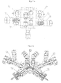
- Fig. 2 a, b For example, the color changer 100 for two colors with the looped paint valves 103, 104 arranged therein, the circulation valves 105, 106 and the cleaning agent valve 101 and the air valve 102 is shown. Inside the color changer 100 runs the common color line 82. The valves are designed as needle valves and are screwed into the color changer 100, which allows easy replacement if necessary.
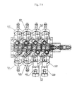
- Fig. 3a . b is a two-component two-color mixer 510 and a hardener with the release valves 501, 503 for the paints and a release valve for the hardener 505. Also screwed are the circulation valves 502, 504, the detergent valves 506, 507 and the air valves 508, 509. Inside the two-component mixer 510 extend the paint line 81 and the hardener line 80. The valves are also designed as needle valves.
- a media plan for a dual color fluid supply device and a color changer 500 mounted on a robot or paint booth is shown schematically.
- the module 1 is identical to the under Fig. 1 described device.
- the module 1 also includes a color changer 100, a pressure regulator 200, a metering pump 300 and a second color changer 400.
- the leading away from the second color changer 400 lines 52, 62 are in this embodiment by the arranged in the color changer 500 of the second module 2 release valves 501st Dragged 503.
- the colors can then be supplied via circulation valves 502, 504 and return lines 53, 63 connected thereto again to the corresponding ink reservoir, which is not shown graphically.
- the release valves 501, 503, as well as the Fig. 4 can be seen, connected via a short line 83 with an atomizer 77.
- Fig. 4 are in the color changer 500 also each a purge valve 508 and a detergent valve 506 installed, which are supplied via the leads 73, 74 respectively with air and detergent. All valves in this in the Fig. 4 illustrated embodiment are also pneumatically on control lines 78 and / or deactivated.
- a next switching possibility of the valves is a presentation of a color.
- a paint 1 via the line 50, through the now open paint valve 103, through the lines 82 and 55a, via the metering pump 300, through the line 55b through the open drain valve 403 in a discharge line 56 is pressed, wherein the circulation valves 106, 502 are closed for the color 1.
- the circulation of the ink 1 via the second color changer 400 to the two-component mixer 510 is interrupted.
- the bypass valve 302 is opened on the metering pump 300, so that the paint can be quickly guided into the discharge line 56 and is not limited in its flow by the passage of the metering pump 300.
- the drain valve 403 is closed. Subsequently, the paint valve 401 and the paint valve 501 can be opened simultaneously and the bypass valve 302 can be closed. Now, the ink 1 is metered via the metering pump 300 into the mixer 76, so that the paint exits from the atomizer 77. The loading of the paint takes place very quickly, since only the distance between the metering pump 300 and the gun of the atomizer 77 must be pressed.
- the paint valves 103, 501 are closed and the circulation valves 106, 502 are opened, so that the paint 1 is again in the circulation mode.
- a fluid supply device according to the in Fig. 4 spray unit 40 shown with a color changer 500, which is mounted on a robot or paint sprayer, is analogous to the in Fig. 1 operated plant operated.
Landscapes
- Nozzles (AREA)
- Spray Control Apparatus (AREA)
Description
- Die vorliegende Erfindung betrifft eine Fluidversorgungsvorrichtung für eine Spritzanlage, insbesondere für eine Farb- oder Lackspritzanlage, und ein Verfahren zu deren Verwendung.
- Für einen Farbwechsel bei einer Spritzanlage muss das System von der verwendeten Farbe gereinigt und anschließend durch die neue Farbe ersetzt werden. Dazu werden bei außen liegenden Pumpen die Zuführleitungen zum Zerstäuber und alle darin befindlichen Teile, wie Farbwechsel, Druckregler oder Dosiereinheiten mit einem Reinigungsfluid gereinigt. Bei solchen Verfahren wird die in der Leitung befindlichen Farbe verworfen, womit ein hoher Verbrauch an Farbe und Reinigungsfluid und eine lange Spülzeit verbunden sind.
- Ein weiteres Verfahren zur Reinigung von Zuführleitungen ist das Zurückmolchen der Farbe in eine Ringleitung und das anschließende Reinigen der Zuführleitungen mit Reinigungsfluid. Bei diesem Verfahren kann zwar der Verlust an Farbe bei einem Farbwechsel relativ gering gehalten werden, aber der technische Aufwand zur Steuerung ist dabei sehr groß, wodurch solche Systeme sehr störanfällig und kostenintensiv sind.
- Die deutsche Offenlegungsschrift
DE 3534269 A1 offenbart ein Farbwechselventil mit mindestens zwei an einem Gehäuse vorgesehenen Zulaufkanälen. Weiterhin beschreibt das Dokument einen zur Farbspritzpistole führenden Kanalausgang und diesem vorgeordnete Absperrventile, welchen Steuereinheiten zugeordnet sind. Die Offenlegungsschrift schlägt unter Verzicht auf ein separates Gehäuse für den Einsatz als addierbarer Einzelbaustein einer Farbwechsel- und Dosieranlage vor, dass das stabförmig ausgebildete Gehäuse ein Mitteilteil besitzt, welches die Zulaufkanäle und seitenversetzt dazu den Kanalausgang aufweist. Darüber hinaus soll vor den beiden Stirnenden unter abnehmbaren Deckeln je eine Ventil-Steuereinheit vorgesehen sein. DokumentDE 3 534 269 A1 offenbart eine Fluidversorgungsvorrichtung für eine Spritzanlage gemäß dem Oberbegriff des Anspruchs 1. - Aus der
DE 10 2004 034 270 A1 ist eine Farbspritzanlage mit Farbwechselsystem bekannt, wobei das Farbwechselsystern einer Spritz- bzw. Austragsvorrichtung zumindest ein aus einer Vielzahl bereit gehaltener Farb-, Lack- und/oder Härterfluide beliebig auswählbares Fluid zuzuführen gestattet. Es ist vorgesehen, dass praktisch alle Leitungen, die zur Sedimentierung neigende Flide führen, ständig von dem jeweiligen Fluid durch strömt werden. -
US 2003157262 A1 beschreibt ein Verfahren zur Erzeugung und zum Spritzen einer Mehrkomponentenfarbe in einer Installation, die eine Hauptleitung umfasst, wobei sich auf der einen Seite der Hauptleitung eine Leitung zur Zuführung einer Grundfarbe befindet und auf den anderen Seite der Hauptleitung eine Spritzanlage vorgesehen ist. Die Hauptleitung beinhaltet eine Kontrolleinrichtung, die die Strömungsgeschwindigkeit des Produkts kontrolliert. - Aus dem US Patent,
US 3857513 ist ein halbautomatisches Farbewechselsystem für eine Farbspritzinstallation bekannt. Das System beinhaltet mehrere Zuführleitungen für Flüssigkeiten, darunter mindestens zwei Farbe-Linien und eine Lösungsmittelleitung. Darüber hinaus weist das System eine von einem Ventil kontrollierte Farbe-Sprühdüse, eine Vorlaufleitung für die Flüssigkeit, einen Druckregler, ein Mittel zur Steuerung des Flüssigkeitsdrucks und ein selektives Mittel zur Steuerung der Flüssigkeitszuleitung. - Ausgehend von diesem Stand der Technik und den in diesem Zusammenhang beschriebenen Nachteilen, bestand die zu lösende Aufgabe somit darin, eine Fluidversorgungsvorrichtung für eine Spritzanlage zur Verfügung zu stellen, die einen schnellen und effizienten Farbwechsel ermöglicht und dabei insbesondere bei der dazu notwendigen Reinigung auf ein Molchsystem verzichtet. Weiterhin soll sich eine solche Fluidversorgungsvorrichtung durch einen geringen Installations- und Kostenaufwand auszeichnen.
- Erfindungsgemäß wird die Aufgabe dadurch gelöst, dass eine Fluidversorgungsvorrichtung für eine Spritzanlage aus zwei Modulen aufgebaut ist.
- Das erste Modul der erfindungsgemäßen Vorrichtung besteht aus:
- mindestens zwei voneinander unabhängigen Ringleitungen oder Vorlaufleitungen für Farben oder Lacke, die mit dem ersten Farbwechsler mit darin angeordneten Farbventilen und Zirkulationsventilen verbunden sind,
- mindestens zwei voneinander unabhängige Leitungen zur Zirkulation der Farben oder Lacke, die von dem ersten Farbwechsler zu einem zweiten Farbwechsler mit darin angeordneten Freigabeventilen geführt werden,
- wobei die Farbventile des ersten Farbwechslers über eine gemeinsame Leitung zum einen mit einem Reinigungsmittelventil und einem Luftventil verbunden sind und zum anderen über eine gemeinsame Druckreglerleitung über einen darin angeordneten Druckregler und eine Dosierpumpe mit den Freigabeventilen, einem Ablassventil sowie einer Ablassleitung des zweiten Farbwechslers verbunden sind.
- Das zweite Modul umfasst mindestens zwei voneinander unabhängige Leitungen zur Zufuhr der Farben oder Lacke von einem zweiten Farbwechsler zu einem dritten Farbwechsler und/oder einem Zweikomponenten-Mischer, wobei der dritte Farbwechsler und/oder der Zweikomponenten-Mischer Freigabeventile und/oder Rücklaufleitungen für Farben oder Lacke aufweist sowie vorzugsweise in unmittelbarer Nähe der Sprühvorrichtung angeordnet ist.
- Eine solche Anlage ermöglicht einen schnellen und effizienten automatischen Farbwechsel, wobei die erfindungsgemäße Ventilanordnung einen geringen Installations- und Kostenaufwand für den Betrieb und insbesondere zur notwendigen Reinigung zulässt. Es werden weiterhin keine aufwendigen Molchsysteme verwendet.
- Die erfindungsgemäße Fluidversorgungsvorrichtung kann im zweiten Modul wahlweise mit einer beliebigen Anzahl an Farbwechslern und/oder Zweikomponenten-Mischern ausgestattet sein. Fluide im Sinne der vorliegenden Erfindung sind alle Fluide, die für eine Oberflächenbehandlung eingesetzt werden können, insbesondere Farb- oder Lacke. Die erfindungsgemäße Vorrichtung gestattet es so mehrere Farben oder Lacke, beispielsweise 20 oder 30 Farben oder Lacke, separat zueinander in der Fluidversorgungsvorrichtung zu transportieren. Unter Reinigungsfluid werden im Sinne der Erfindung geeignete Lösungsmittel verstanden, die die jeweiligen Farben und Lacke vollständig entfernen können. Vorteilhaft ist es, wenn ein Zweikomponenten-Mischer im zweiten Modul vorhanden ist, dieses Modul mit einer Zuleitung für einen Härter zu versehen, wobei die Dosierung des Härters durch ein Ventil, im nachfolgenden als Härterventil bezeichnet, erfolgt. Somit ist es möglich, dem Lack und/oder einer Lackmischung ein Härter beizumischen. Vorteilhaft ist es ferner, wenn der Farbwechsler Zirkulationsventile aufweist. Vorteilhaft werden für die Zirkulationsventile, Farbventile und Härterventile Nadelventile verwendet, wobei diese über Steuerleitungen pneumatisch an- und/oder absteuerbar sind. Die Steuerung erfolgt vorteilhaft rechnerbasiert, beispielsweise über ein SPS-System. Bei einer vorteilhaften Ausgestaltung der Fluidversorgungsvorrichtung ist die Dosierpumpe im ersten Modul über ein separates Spülventil mit einer Reinigungsmittelleitung verbunden; somit kann diese Dosierpumpe mit einem Reinigungsmittel unabhängig vom übrigen System gespült werden, wobei besonders vorteilhaft die Dosierpumpe eine spülbare Zahnraddosierpumpe ist. Bei einer weiteren vorteilhaften Ausführung ist das erste Modul außerhalb einer Kabine oder an eine Kabinenwand und das zweite Modul an einem Roboter oder Lackierautomaten montiert.
- Ein erfindungsgemäßes Verfahren zum betrieb der Fluidversorgungsvorrichtung für eine spritzanlage gemäß Anspruch 1, wird nachfolgend dargestellt:
- Dabei werden in einem ersten Modul über mindestens zwei voneinander unabhängige Vorlaufleitungen Farben oder Lacke in den ersten Farbwechsler mit darin angeordneten Farbventilen und Zirkulationsventilen eingeleitet. Über mindestens zwei voneinander unabhängige Leitungen zur Zirkulation der Farben oder Lacke können diese von dem ersten Farbwechsler zu einem zweiten Farbwechsler mit darin angeordneten Freigabeventilen geführt werden. Weiterhin werden die Farben oder Lacke über mindestens zwei voneinander unabhängige Leitungen vom zweiten Farbwechsler einem in einem zweiten Modul angeordneten dritten Farbwechsler und/oder einem Zweikomponenten-Mischer zugeführt. Wenn es zweckdienlich ist, können im zweiten Modul prinzipiell auch zwei oder mehrere Farbwechsler und/oder Zweikomponenten-Mischer sowie beliebige Kombinationen aus diesen angeordnet sein. Die Farben können somit in separaten Kreisläufen ständig durch das System zirkulieren oder bei entsprechender Ventilschaltung wahlweise vom dritten Farbwechsler und/oder vom Zweikomponenten-Mischer einer Sprühvorrichtung zugeleitet werden. Im Reinigungsmodus wird Luft und/oder ein flüssiges Reinigungsmittel durch den ersten Farbwechsler, durch eine gemeinsame Leitung mit einem darin angeordneten Druckregler und einer Dosierpumpe über den zweiten Farbwechsler durch ein Ablassventil in eine Ablassleitung geleitet. Weiterhin wird gleichzeitig Luft und/oder ein flüssiges Reinigungsmittel durch den dritten Farbwechsler und/oder den Zweikomponenten-Mischer und die Sprühvorrichtung geleitet. Besonders zweckmäßig wird zum Zweck der Reinigung abwechselnd flüssiges Reinigungsmittel und Luft durch die genannten Komponenten gepulst, wobei die Gestaltung der Pulsierung an das zu entfernende Fluid anzupassen ist. Eine Reinigung kann gegebenenfalls auch ausschließlich mit einem flüssigen Reinigungsmittel ohne Luft erfolgen.
- Die erfindungsgemäße Fluidversorgungsvorrichtung hat weiterhin die Vorteile, dass trotz einer außen liegenden Dosierpumpe, die Farben durch die komplette Vorrichtung zirkulieren und die Zirkulation zu oder abgeschaltet werden kann. Weiterhin ist es von Vorteil, dass es zu einem sehr geringen Verlust an Farbe und Reinigungsmittel kommt, ein schneller Farbwechsel trotz außen liegender Pumpen, eine einfache und schnelle Zugänglichkeit zu allen Bauteilen gegeben ist und der Aufwand für die Technik und den Steuerungsbau gegenüber einem Molchsystem sehr gering ist.
- Die erfindungsgemäße Fluidversorgungsvorrichtung für eine Spritzanlage kann beispielsweise zur Beschichtung einer Oberfläche mit einem Lack, vorzugsweise in einer Lackbeschichtungsanlage, eingesetzt werden.
- Ein Ausführungsbeispiel der Erfindung ist in den Zeichnungen dargestellt und wird im Folgenden näher beschrieben. Es zeigen:
- Fig. 1
- einen Medienplan für eine Fluidversorgungsvorrichtung mit zwei Farben mit einem Zweikomponenten-Mischer, der auf einem Ro- boter oder Lackierautomaten montiert ist,
- Fig. 2 a,
- b einen Farbwechsler mit Zirkulationsventilen,
- Fig. 3 a,
- b einen Zweikomponenten-Mischer mit Zirkulationsventilen und
- Fig. 4
- einen Medienplan für eine Fluidversorgungsvorrichtung mit zwei Farben mit einem Farbwechsler, der auf einem Roboter oder La- ckierautomaten montiert ist.
- In
Fig. 1 zeigt eine beispielhafte Fluidversorgungsvorrichtung für eine Farbspritzanlage 40 für zwei Farben. Dabei besteht die Vorrichtung aus zwei Modulen 1, 2, wobei das erste Modul 1 an einer Kabinenwand und das zweite Modul 2 auf einem Roboter oder Lackierautomaten montiert ist. Die beiden Farben werden in das erste Modul 1 über zwei voneinander unabhängige Vorlaufleitungen 50, 60 für Farben eingeleitet und im ersten Farbwechsler 100 durch die darin angeordneten Farbventile 103, 104 durchgeschleift und zu ebenfalls im ersten Farbwechsler 100 befindlichen Zirkulationsventilen 105, 106 geleitet. An die Ausgänge dieser Zirkulationsventile 105, 106 sind jeweils eine Leitung 51, 61 zur Zirkulation der Farben angebracht. Diese Leitungen enden an den Farbventilen 401, 402 des zweiten Farbwechslers 400. Die Farben können durch diese Farbventile 401, 402 ebenfalls durchgeschleift werden und über die angeschlossenen Leitungen 52, 62 durch die im Zweikomponenten-Mischer 510 des zweiten Moduls 2 angeordneten Freigabeventile 501, 503 geschleift werden. Die Farben können dann über Zirkulationsventile 502, 504 und daran angeschlossene Rücklaufleitungen 53, 63 wieder den entsprechenden zeichnerisch nicht dargestellten Farbreservoiren zugeführt werden. Somit können die Farben durch das gesamte System zirkulieren. - Im Zweikomponenten-Mischer 510 des zweiten Moduls 2 sind, wie ebenfalls der
Fig. 1 zu entnehmen ist, die Freigabeventile 501, 503 über eine kurze Leitung 81 mit einem Mischer 76 verbunden, an den ein Zerstäuber 77 zum Aufbringen von Farben auf Oberflächen angeschlossen ist. Weiterhin kann derFig. 1 entnommen werden, dass dem Mischer 76 durch ein im Zweikomponenten-Mischer 510 angeordnetes Freigabeventil 505 ein Härter zugeführt werden kann. Der Härter wird dabei über eine Leitung 75 und eine zeichnerisch nicht dargestellte Pumpe herangeführt und dem Mischer 76 über die Leitung 80 zugeführt. Gemäß derFig. 1 sind im Zweikomponenten-Mischer 510 außerdem jeweils zwei Spülluftventile 508, 509 und zwei Reinigungsmittelventile 506, 507 eingebaut, die über die Zuleitungen 73, 74 entsprechend mit Luft und Reinigungsmittel versorgt werden können. - Alle Ventile in diesem in der
Fig. 1 dargestellten Ausführungsbeispiel werden pneumatisch über Steuerleitungen 78 an- und/oder abgesteuert. Dabei kennzeichnen die dargestellten Steuerleitungen 78 jeweils schematisch die Gesagtheit der Einzelsteuerleitungen, da alle Ventile separat gesteuert werden können. - Wie weiterhin aus der
Fig. 1 hervorgeht, sind die Farbventile 103, 104 im ersten Farbwechsler 100 über eine Leitung 82 mit einem Reinigungsmittelventil 101 und einem Luftventil 102 verbunden, wobei letztere über die Leitungen 70, 71 entsprechend mit Pulsluft und Reinigungsmittel versorgt werden. Weiterhin führt eine gemeinsame Leitung 55a von den Farbventilen 103, 104 über einen Druckregler 200 zu einer 6 ccm Dosierpumpe 300. Die Dosierpumpe 300 ist weiterhin über eine Leitung 55b an die Freigabeventile 401, 402 des zweiten Farbwechslers 400 angeschlossen und über ein Ablassventil 403 mit einer Ablassleitung 56 verbunden. - Gemäß der
Fig. 1 ist die Dosierpumpe 300 als eine spülbare Zahnraddosierpumpe ausgeführt. Diese ist über ein Spülventil 301 und eine separate Leitung 79 mit einem Reinigungsmittel spülbar. - In
Fig. 2 a, b ist der Farbwechsler 100 für zwei Farben mit den darin angeordneten, durchgeschleiften Farbventilen 103, 104, den Zirkulationsventilen 105, 106 sowie dem Reinigungsmittelventil 101 und dem Luftventil 102 dargestellt. Im Inneren des Farbwechslers 100 verläuft die gemeinsame Farbleitung 82. Die Ventile sind dabei als Nadelventile ausgeführt und sind in den Farbwechsler 100 eingeschraubt, was bei Bedarf einen einfachen Austausch ermöglicht. - In
Fig. 3a ,b ist ein Zweikomponenten-Mischer 510 für zwei Farben und einen Härter mit den Freigabeventilen 501, 503 für die Farben und einem Freigabeventil für den Härter 505. Ebenfalls eingeschraubt sind die Zirkulationsventile 502, 504, die Reinigungsmittelventile 506, 507 sowie die Luftventile 508, 509. Im Inneren des Zweikomponenten-Mischers 510 verlaufen die Farbleitung 81 und die Härterleitung 80. Die Ventile sind dabei ebenfalls als Nadelventile ausgeführt. - In
Fig. 4 ist ein Medienplan für eine Fluidversorgungsvorrichtung mit zwei Farben und einem Farbwechsler 500, der auf einem Roboter oder Lackierautomaten montiert ist, schematisch dargestellt. Dabei ist das Modul 1 baugleich zu der unterFig. 1 beschriebenen Vorrichtung. Somit enthält das Modul 1 ebenfalls einen Farbwechsler 100, einen Druckregler 200, eine Dosierpumpe 300 und einen zweiten Farbwechsler 400. Die vom zweiten Farbwechsler 400 wegführenden Leitungen 52, 62 werden in diesem Ausführungsbeispiel durch die in dem Farbwechsler 500 des zweiten Moduls 2 angeordneten Freigabeventile 501, 503 geschleift. Die Farben können dann über Zirkulationsventile 502, 504 und daran angeschlossene Rücklaufleitungen 53, 63 wieder den entsprechenden zeichnerisch nicht dargestellten Farbreservoiren zugeführt werden. - Im Farbwechsler 500 des zweiten Moduls 2 sind die Freigabeventile 501, 503, wie ebenfalls der
Fig. 4 zu entnehmen ist, über eine kurze Leitung 83 mit einem Zerstäuber 77 verbunden. - Gemäß der
Fig. 4 sind im Farbwechsler 500 außerdem jeweils ein Spülluftventil 508 und ein Reinigungsmittelventil 506 eingebaut, die über die Zuleitungen 73, 74 entsprechend mit Luft und Reinigungsmittel versorgt werden. Alle Ventile in diesem in derFig. 4 dargestellten Ausführungsbeispiel werden ebenfalls pneumatisch über Steuerleitungen 78 an- und/oder abgesteuert. - Im Folgenden wird die Fluidversorgung einer erfindungsgemäßen Spritzanlage 40 mit einem Zweikomponenten-Mischer 510, der auf einem Roboter oder Lackierautomaten montiert ist, beschrieben. Dazu erfolgt unter Verwendung der Anlage gemäß
Fig. 1 eine Zirkulation der zwei Farben, indem diese aus zeichnerisch nicht dargestellten Reservoirs über die Vorlaufleitungen 50, 60 durch die geschlossenen Farbventile 103, 104 durchgeschleift und durch die offenen Zirkulationsventile 105, 106 in die Leitungen 51, 61 gedrückt werden. Aus diesen Leitungen werden die Farben dann durch die geschlossenen Farbventile 401, 402 durchgeschleift und über die Leitungen 52, 62 auch durch die geschlossenen Farbventile 501, 503 geschleift. Durch den Rücklauf der Farben über die offenen Zirkulationsventile 502, 504 und die Leitungen 53, 63 wird die Zirkulation der Farben durch das System vervollständigt. In einer nächsten Schaltmöglichkeit der Ventile erfolgt ein Vorlegen einer Farbe. Dazu wird beispielsweise eine Farbe 1 über die Leitung 50, durch das jetzt geöffnete Farbventil 103, durch die Leitungen 82 und 55a, über die Dosierpumpe 300, durch die Leitung 55b durch das offene Ablassventil 403 in eine Ablassleitung 56 gedrückt, wobei die Zirkulationsventile 106, 502 für die Farbe 1 geschlossen sind. Somit ist die Zirkulation der Farbe 1 über den zweiten Farbwechsler 400 zum Zweikomponentenmischer 510 unterbrochen. Während des Vorlegens der Farbe ist das Bypassventil 302 an der Dosierpumpe 300 geöffnet, so dass die Farbe schnell bis in die Ablassleitung 56 geführt werden kann und in ihrem Fluss nicht durch den Durchlass der Dosierpumpe 300 limitiert wird. Wenn die Strecke zwischen dem Farbventil 103 bis zur Ablassleitung 56 komplett mit Farbe 1 bestückt ist, wird das Ablassventil 403 geschlossen. Anschließend können das Farbventil 401 und das Farbventil 501 gleichzeitig geöffnet werden und das Bypassventil 302 geschlossen werden. Jetzt wird die Farbe 1 über die Dosierpumpe 300 in den Mischer 76 dosiert, so dass die Farbe aus dem Zerstäuber 77 austritt. Das Laden der Farbe erfolgt dabei sehr schnell, da lediglich die Strecke zwischen der Dosierpumpe 300 und der Pistole des Zerstäubers 77 angedrückt werden muss. Beim Wechseln der Farbe werden die Farbventile 103, 501 geschlossen und die Zirkulationsventile 106, 502 geöffnet, so dass sich die Farbe 1 wieder im Zirkulationsmodus befindet. Zum Reinigen wird lediglich abwechselnd Luft und ein Lösungsmittel vom ersten Farbwechsler 100 über den Druckregler 200 und durch die Dosierpumpe 300 aus dem Ablassventil 403 gespült. Da diese Strecke sehr kurz ist, kann das Reinigen in kürzester Zeit und mit geringem Lösungsmittelverbrauch durchgeführt werden. Gleichzeitig wird die Strecke vom Zweikomponenten-Mischer 510 bis zum Zerstäuber 77 gereinigt. Da auch diese Strecke sehr kurz gestaltet ist, kann das Reinigen auch hier in kürzester Zeit und mit geringem Lösungsmittelverbrauch durchgeführt werden. - Eine Fluidversorgungsvorrichtung gemäß der in
Fig. 4 dargestellten Spritzanlage 40 mit einem Farbwechsler 500, der auf einem Roboter oder Lackierautomaten montiert ist, wird in analoger Weise zu der inFig. 1 dargestellten Anlage betrieben. -
- 1
- erstes Modul
- 2
- zweites Modul
- 40
- Farbspritzanlage
- 50
- Leitung Farbe oder Lack 1, Vorlauf
- 51
- Leitung Farbe oder Lack 1, Zirkulation
- 52
- Leitung Farbe oder Lack 1, zum dritten Farbwechsler oder Zweikompo- nenten-Mischer
- 53
- Leitung Farbe oder Lack 1, Rücklauf
- 55a
- Druckreglerleitung, vor der Dosierpumpe
- 55b
- Druckreglerleitung, nach der Dosierpumpe
- 56
- Ablassleitung
- 60
- Leitung Farbe oder Lack 2, Vorlauf
- 61
- Leitung Farbe oder Lack 2, Zirkulation
- 62
- Leitung Farbe oder Lack 2, zum dritten Farbwechster oder Zweikompo- nenten-Mischer
- 63
- Leitung Farbe oder Lack 2, Rücklauf
- 70
- Zuleitung, Pulsluft
- 71
- Zuleitung, Reinigungsmittel
- 73
- Zuleitung an Roboter oder Lackierautomat, Luft
- 74
- Zuleitung an Roboter oder Lackierautomat, Reinigungsmittel
- 75
- Zuleitung, Härter
- 76
- Mischerelement
- 77
- Sprühvorrichtung oder Zerstäuber
- 78
- Steuerleitungen
- 79
- Reinigungsmittelleitung, Dosierpumpe
- 80
- Härterleitung, im Zweikomponenten-Mischer
- 81
- Farbleitung, im Zweikomponenten-Mischer
- 82
- Farbleitung, im ersten Farbwechsler
- 83
- Farbleitung, im dritten Farbwechsler
- 100
- erster Farbwechsler
- 101
- Reinigungsmittelventil
- 102
- Luftventil
- 103
- Farbventil, Farbe oder Lack 1
- 104
- Farbventil, Farbe oder Lack 2
- 105
- Zirkulationsventil , Farbe oder Lack 2
- 106
- Zirkulationsventil , Farbe oder Lack 1
- 200
- Druckregler
- 300
- Dosierpumpe oder Zahnraddosierpumpe, spülbar
- 301
- Spülventil für Dosierpumpe
- 302
- Bypassventil für Dosierpumpe
- 400
- zweiter Farbwechsler
- 401
- Freigabeventil, Farbe oder Lack 1
- 402
- Freigabeventil, Farbe oder Lack 2
- 403
- Ablassventil
- 500
- dritter Farbwechsler
- 501
- Freigabeventil, Farbe oder Lack 1
- 502
- Zirkulationsventil , Farbe oder Lack 1
- 503
- Freigabeventil, Farbe oder Lack 2
- 504
- Zirkulationsventil , Farbe oder Lack 2
- 505
- Freigabeventil, Härter
- 506
- Reinigungsmittelventil
- 507
- Reinigungsmittelventil
- 508
- Spülluftventil
- 509
- Spülluftventil
- 510
- Zweikomponenten-Mischer
Claims (14)
- Fluidversorgungsvorrichtung für eine Spritzanlage, umfassend
ein erstes Modul (1) mit- mindestens zwei voneinander unabhängigen Vorlaufleitungen (50, 60) für Farben oder Lacke, die mit einem ersten Farbwechsler (100) mit darin angeordneten Farbventilen (103, 104) und Zirkulationsventilen (105, 106) verbunden sind,- mindestens zwei voneinander unabhängigen Leitungen (51, 61) zur Zirkulation der Farben oder Lacke,- wobei die Farbventile (103, 104) des ersten Farbwechslers (100) über eine gemeinsame Leitung (82) zum einen mit einem Reinigungsmittelventil (101) und einem Luftventil (102) verbunden sind,
dadurch gekennzeichnet, dass- die zwei Leitungen (51, 61) den ersten Farbwechsler (100) mit einem zweiten Farbwechsler (400) mit darin angeordneten Freigabeventilen (401, 402) verbinden,- die Farbventile (103, 104) des ersten Farbwechslers (100) zum anderen über eine gemeinsame Druckreglerleitung (55a, 55b) über einen darin angeordneten Druckregler (200) und eine Dosierpumpe (300) mit den Freigabeventilen (401, 402), einem Ablassventil (403) sowie einer Ablassleitung (56) des zweiten Farbwechslers (400) verbunden sind und- die Vorrichtung zusätzlich ein zweites Modul (2) aufweist, bestehend aus mindestens zwei voneinander unabhängigen Leitungen (52, 62) zur Zufuhr der Farben oder Lacke vom zweiten Farbwechsler (400) zu einem dritten Farbwechsler (500) und/oder einem Zweikomponenten-Mischer (510), wobei der dritte Farbwechsler (500) und/oder der Zweikomponenten-Mischer (510) Freigabeventile (501, 503) und Rücklaufleitungen (53, 63) aufweist sowie unmittelbar in der Nähe von einer Sprühvorrichtung (77) angeordnet ist. - Fluidversorgungsvorrichtung nach Anspruch 1 für eine Farb- oder Lackspritzanlage (40).
- Fluidversorgungsvorrichtung nach Anspruch 1, dadurch gekennzeichnet, dass in den Zweikomponenten-Mischer (510) ein Härterventil (505) eingebaut oder eingeschraubt ist, das mit einer Zuführleitung (75) für einen Härter verbunden ist.
- Fluidversorgungsvorrichtung nach den Ansprüchen 1 und 2, dadurch gekennzeichnet, dass die Zirkulationsventile in die Farbwechsler eingebaut oder eingeschraubt sind.
- Fluidversorgungsvorrichtung nach den Ansprüchen 1 bis 3, dadurch gekennzeichnet, dass die Zirkulationsventile und/oder Farbventile Nadelventile sind.
- Fluidversorgungsvorrichtung nach den Ansprüchen 1 bis 4, dadurch gekennzeichnet, dass die Dosierpumpe (300) eine spülbare Zahnraddosierpumpe ist.
- Fluidversorgungsvorrichtung nach den Ansprüchen 1 bis 5, dadurch gekennzeichnet, dass die Zirkulationsventile und die Farbventile über Steuerleitungen (78) ansteuerbar sind.
- Fluidversorgungsvorrichtung nach den Ansprüchen 1 bis 7, dadurch gekennzeichnet, dass die Zirkulationsventile und die Farbventile über Steuerleitung (78) pneumatisch ansteuerbar sind.
- Fluidversorgungsvorrichtung nach den Ansprüchen 1 bis 6, dadurch gekennzeichnet, dass das erste Modul (1) außerhalb einer Kabine oder an einer Kabinenwand montiert ist.
- Fluidversorgungsvorrichtung nach den Ansprüchen 1 bis 7, dadurch gekennzeichnet, dass das zweite Modul (2) an einem Roboter oder Lackierautomaten montiert ist.
- Fluidversorgungsvorrichtung nach den Ansprüchen 1 bis 8, dadurch gekennzeichnet, dass die Dosierpumpe (300) über ein separates Spülventil (301) mit einer Reinigungsmittelleitung (79) verbunden ist.
- Verfahren zum Betrieb der Fluidversorgungsvorrichtung für eine Spritzanlage gemäß Anspruch 1, dadurch gekennzeichnet, dass Farben oder Lacke- in dem ersten Modul (1) über mindestens zwei voneinander unabhängige Vorlaufleitungen (50, 60) für Farben oder Lacke in den ersten Farbwechsler (100) mit darin angeordneten Farbventilen (103, 104) und Zirkulationsventilen (105, 106) eingeleitet werden,- über mindestens zwei voneinander unabhängige Leitungen (51, 61) zur Zirkulation der Farben oder Lacke von dem ersten Farbwechsler zu dem zweiten Farbwechsler (400) mit darin angeordneten Freigabeventilen (401, 402) zugeführt werden oder über die gemeinsame Leitung (55a, 55b) vom ersten Farbwechsler (100) über den zweiten Farbwechsler (400) über das Ablassventil (403) der Ablassteitung zugeführt werden,- sowie über mindestens zwei voneinander unabhängige Leitungen (52, 62) zur Zufuhr der Farben oder Lacke vom zweiten Farbwechsler (400) zu dem in dem zweiten Modul (2) angeordneten dritten Farbwechsler (500) und/oder dem Zweikomponenten-Mischer (510) zugeführt von diesem in einen Zerstäuber oder in die separaten Rücklaufleitungen (53, 63) geleitet werden,- wobei im Reinigungsmodus Luft und/oder ein flüssiges Reinigungsmittel durch den ersten Farbwechsler (100), durch die gemeinsame Leitung (55a, 55b) mit dem darin angeordneten Druckregler (200) und der Dosierpumpe (300) über den zweiten Farbwechsler (400) durch das Ablassventil (403) der Ablassleitung geleitet wird sowie Luft und/oder ein flüssiges Reinigungsmittel durch den dritten Farbwechsler (500) und/oder den Zweikomponenten-Mischer (510) und die Sprühvorrichtung (77) geleitet wird.
- Verwendung der Fluidversorgungsvorrichtung für eine Spritzanlage nach Anspruch 1 zur Beschichtung einer Oberfläche mit einem Lack.
- Verwendung der Fluidversorgungsvorrichtung für eine Spritzanlage nach Anspruch 1 in einer Lackbeschichtungsanlage.
Applications Claiming Priority (2)
| Application Number | Priority Date | Filing Date | Title |
|---|---|---|---|
| DE102006048037A DE102006048037B4 (de) | 2006-10-09 | 2006-10-09 | Fluidversorgungsvorrichtung für eine Spritzanlage |
| PCT/EP2007/058906 WO2008043602A1 (de) | 2006-10-09 | 2007-08-28 | Fluidversorgungseinrichtung für eine spritzanlage |
Publications (2)
| Publication Number | Publication Date |
|---|---|
| EP2076336A1 EP2076336A1 (de) | 2009-07-08 |
| EP2076336B1 true EP2076336B1 (de) | 2010-04-21 |
Family
ID=38664072
Family Applications (1)
| Application Number | Title | Priority Date | Filing Date |
|---|---|---|---|
| EP07819973A Not-in-force EP2076336B1 (de) | 2006-10-09 | 2007-08-28 | Fluidversorgungsvorrichtung für eine spritzanlage |
Country Status (7)
| Country | Link |
|---|---|
| US (1) | US20110076411A1 (de) |
| EP (1) | EP2076336B1 (de) |
| CN (1) | CN101563169B (de) |
| AT (1) | ATE464951T1 (de) |
| DE (2) | DE102006048037B4 (de) |
| ES (1) | ES2345071T3 (de) |
| WO (1) | WO2008043602A1 (de) |
Cited By (2)
| Publication number | Priority date | Publication date | Assignee | Title |
|---|---|---|---|---|
| EP2542349B1 (de) | 2010-03-03 | 2016-02-24 | Dürr Systems GmbH | Zerstäuber und verfahren zum applizieren von ein- und mehr-komponenten-beschichtungsmitteln |
| EP2498916B1 (de) | 2009-11-11 | 2017-01-11 | Dürr Systems AG | Vorrichtung und verfahren zur konservierung von bauteilen |
Families Citing this family (20)
| Publication number | Priority date | Publication date | Assignee | Title |
|---|---|---|---|---|
| DE102009031180A1 (de) * | 2009-06-29 | 2010-12-30 | Magna Steyr Fahrzeugtechnik Ag & Co Kg | Vorrichtung zur Beschichtung eines Werkstückes |
| DE102010019612A1 (de) * | 2010-05-06 | 2011-11-10 | Dürr Systems GmbH | Beschichtungseinrichtung, insbesondere mit einem Applikationsgerät, und zugehöriges Beschichtungsverfahren, das einen zertropfenden Beschichtungsmittelstrahl ausgibt |
| EP2425899B1 (de) * | 2010-09-06 | 2013-08-21 | LacTec GmbH | Farbwechsler |
| ITVR20110242A1 (it) * | 2011-12-30 | 2013-07-01 | Todesco S R L | Apparecchiatura di verniciatura |
| CN102641812A (zh) * | 2012-04-05 | 2012-08-22 | 清华大学 | 喷涂机器人用防沉淀供料系统 |
| CN102989726B (zh) * | 2012-11-29 | 2015-06-10 | 奇瑞汽车股份有限公司 | 自动喷涂机器人外接阀管路清洗装置 |
| DE102013013530A1 (de) * | 2013-08-13 | 2015-03-12 | Dürr Systems GmbH | Applikationssystem mit seilgeführter Handhabungsvorrichtung zum Bewegen eines Applikationsgeräts |
| DE102014010864A1 (de) | 2014-07-24 | 2016-01-28 | Eisenmann Ag | Beschichtungssystem zum Beschichten von Gegenständen |
| ES2661586T3 (es) * | 2014-08-19 | 2018-04-02 | Abb Schweiz Ag | Cambiador de color |
| DE102015007158A1 (de) * | 2015-06-03 | 2016-12-08 | Eisenmann Se | Beschichtungssystem zum Beschichten von Gegenständen |
| DE102015008661A1 (de) | 2015-07-03 | 2017-01-05 | Dürr Systems Ag | Nadelventil |
| DE102015008659B4 (de) | 2015-07-03 | 2019-06-19 | Dürr Systems Ag | Beschichtungsmittelventil und Rotationszerstäuber |
| CN105772286B (zh) * | 2016-05-20 | 2019-05-07 | 湖南墨林自动化科技有限公司 | 一种数控木门喷漆机 |
| CN110785239A (zh) | 2017-04-21 | 2020-02-11 | J·瓦格纳有限责任公司 | 用于液体的静电雾化器和用于操作静电雾化器的方法 |
| CN107199135B (zh) * | 2017-08-04 | 2022-12-13 | 天津铭捷智能装备有限公司 | 旋杯的内部阀岛 |
| US20200023415A1 (en) * | 2018-07-20 | 2020-01-23 | Advanflo Technologies Co., Ltd. | Automatic cleaning and spraying device |
| DE102019130920A1 (de) * | 2019-11-15 | 2021-05-20 | Dürr Systems Ag | Farbversorgungssystem für eine Beschichtungsanlage und zugehöriges Betriebsverfahren |
| CN113617566B (zh) * | 2020-05-06 | 2022-11-04 | 上海发那科机器人有限公司 | 双固化剂使用的混合模块及其工作方法 |
| CN112642613B (zh) * | 2020-12-21 | 2021-09-17 | 山东中清智能科技股份有限公司 | 一种喷漆用一体化系统 |
| CN116786300B (zh) * | 2023-06-26 | 2025-12-05 | 北京兴信易成机电工程有限公司 | 一种用于供漆的定量走珠式快速换色系统走珠接收站 |
Family Cites Families (11)
| Publication number | Priority date | Publication date | Assignee | Title |
|---|---|---|---|---|
| US3857513A (en) * | 1967-10-20 | 1974-12-31 | Gyromat Corp | Semi-automatic color change system for paint spray installation |
| DE3534269A1 (de) * | 1985-09-26 | 1987-04-02 | Richard C Walther Gmbh & Co Kg | Farbwechselventil |
| DE19543458A1 (de) * | 1995-11-22 | 1997-05-28 | Ekkehard Senf | Windkraftanlage |
| DE29719535U1 (de) * | 1997-11-04 | 1998-02-05 | APSON Lackiertechnik GmbH, 63067 Offenbach | Vielfarb-Lackiereinrichtung |
| US6328799B1 (en) * | 1998-11-13 | 2001-12-11 | Toyota Jidosha Kabushiki Kaisha | Coating apparatus and a method of assembling the same |
| FR2809970B1 (fr) * | 2000-06-08 | 2003-09-05 | Eisenmann France Sarl | Procede de realisation et d'application par pulverisation d'une peinture multi-composants |
| US6513729B2 (en) * | 2000-08-29 | 2003-02-04 | Honda Giken Kogyo Kabushiki Kaisha | Two-package-mixing discharging device and two-package-mixing coating device |
| DE10115463A1 (de) * | 2001-03-29 | 2002-10-02 | Duerr Systems Gmbh | Zerstäuber für eine Beschichtungsanlage und Verfahren zu seiner Materialversorgung |
| DE10235102B4 (de) * | 2002-08-01 | 2006-07-27 | Lac Tec GmbH Gesellschaft für moderne Lackiertechnik | Lackiereinrichtung mit einer molchbaren Ventileinrichtung |
| US7399363B2 (en) * | 2002-10-23 | 2008-07-15 | Fanuc Robotics America, Inc. | Robotic apparatus for painting |
| DE102004034270B4 (de) * | 2004-07-15 | 2016-08-18 | Wolfgang Schmidt | Anlage zum Austragen fließfähiger Fluide, insbesondere von Farben und Lacken und Verfahren zum Betrieb der Anlage |
-
2006
- 2006-10-09 DE DE102006048037A patent/DE102006048037B4/de not_active Expired - Fee Related
-
2007
- 2007-08-28 AT AT07819973T patent/ATE464951T1/de active
- 2007-08-28 WO PCT/EP2007/058906 patent/WO2008043602A1/de not_active Ceased
- 2007-08-28 DE DE502007003542T patent/DE502007003542D1/de active Active
- 2007-08-28 CN CN2007800375509A patent/CN101563169B/zh not_active Expired - Fee Related
- 2007-08-28 ES ES07819973T patent/ES2345071T3/es active Active
- 2007-08-28 EP EP07819973A patent/EP2076336B1/de not_active Not-in-force
- 2007-08-28 US US12/443,695 patent/US20110076411A1/en not_active Abandoned
Cited By (3)
| Publication number | Priority date | Publication date | Assignee | Title |
|---|---|---|---|---|
| EP2498916B1 (de) | 2009-11-11 | 2017-01-11 | Dürr Systems AG | Vorrichtung und verfahren zur konservierung von bauteilen |
| EP2542349B1 (de) | 2010-03-03 | 2016-02-24 | Dürr Systems GmbH | Zerstäuber und verfahren zum applizieren von ein- und mehr-komponenten-beschichtungsmitteln |
| US9844793B2 (en) | 2010-03-03 | 2017-12-19 | Durr Systems Gmbh | Atomizer and method for applying one-and multi-component coating agents |
Also Published As
| Publication number | Publication date |
|---|---|
| DE102006048037A1 (de) | 2008-04-17 |
| CN101563169A (zh) | 2009-10-21 |
| ATE464951T1 (de) | 2010-05-15 |
| CN101563169B (zh) | 2012-10-10 |
| US20110076411A1 (en) | 2011-03-31 |
| ES2345071T3 (es) | 2010-09-14 |
| WO2008043602A1 (de) | 2008-04-17 |
| DE502007003542D1 (de) | 2010-06-02 |
| EP2076336A1 (de) | 2009-07-08 |
| DE102006048037B4 (de) | 2010-07-08 |
Similar Documents
| Publication | Publication Date | Title |
|---|---|---|
| EP2076336A1 (de) | Fluidversorgungseinrichtung für eine spritzanlage | |
| EP3554716B1 (de) | Applikationsvorrichtung und verfahren zum applizieren eines beschichtungsmittels | |
| DE69622407T2 (de) | Lackierroboter mit system zum lackzufuhr | |
| EP2983833A1 (de) | Wechseleinrichtung für beschichtungsmedien und beschichtungssystem zum beschichten von gegenständen | |
| EP2542349B1 (de) | Zerstäuber und verfahren zum applizieren von ein- und mehr-komponenten-beschichtungsmitteln | |
| EP2361691A1 (de) | Fluidweiche | |
| EP1314483A2 (de) | Verfahren und Versorgungssystem zur dosierten Materialversorgung einer Beschichtungsvorrichtung | |
| DE102004034270B4 (de) | Anlage zum Austragen fließfähiger Fluide, insbesondere von Farben und Lacken und Verfahren zum Betrieb der Anlage | |
| DE3717929C2 (de) | ||
| EP1095707B1 (de) | Farbwechselventilanordnung und Verfahren zum Spülen eines Farbwechslers | |
| DE60127273T2 (de) | Verfahren und vorrichtung zur befüllung eines farbbehälters in einer automatisch arbeitenden beschichtunganlage | |
| EP0541745B1 (de) | Sprühbeschichtungsvorrichtung | |
| DE102015110312B4 (de) | Pulverweiche und Pulverabgabesystem mit Pulverweiche | |
| EP0104395B1 (de) | Farbmischverfahren und Farbmischeinrichtung zur Verfahrensdurchführung | |
| DE10342643A1 (de) | Verfahren zum Betrieb einer Medien-Förderanlage | |
| DE102004038017A1 (de) | Verfahren und Vorrichtung für einen zeitlich nacheinander erfolgenden Austrag unterschiedlicher Farben bzw. Lacke | |
| WO2024165408A1 (de) | Beschichtungsmittel-versorgungseinrichtung und zugehöriges betriebsverfahren | |
| DE202006015557U1 (de) | Fluidversorgungsvorrichtung für eine Spritzanlage | |
| DE3312268A1 (de) | Farbumlaufanlage fuer eine lackieranlage | |
| EP1369182B1 (de) | Lackiereinrichtung | |
| EP3012028B1 (de) | Kolbendosierer für fluide Medien und System zum Beschichten von Gegenständen | |
| EP1632700B1 (de) | Ventilvorrichtung | |
| EP1522348B1 (de) | Verfahren und System zur Versorgung von Materialverbrauchern über Molchstrecken | |
| DE102017000730A1 (de) | Farbzuführ- und Mischvorrichtung für eine Mehrkomponenten-Spritzpistole | |
| DE102024131022A1 (de) | Versorgungssystem zum Versorgen zumindest eines Applikationsgeräts mit einem Applikationsmittel |
Legal Events
| Date | Code | Title | Description |
|---|---|---|---|
| PUAI | Public reference made under article 153(3) epc to a published international application that has entered the european phase |
Free format text: ORIGINAL CODE: 0009012 |
|
| 17P | Request for examination filed |
Effective date: 20090406 |
|
| AK | Designated contracting states |
Kind code of ref document: A1 Designated state(s): AT BE BG CH CY CZ DE DK EE ES FI FR GB GR HU IE IS IT LI LT LU LV MC MT NL PL PT RO SE SI SK TR |
|
| 17Q | First examination report despatched |
Effective date: 20090724 |
|
| GRAP | Despatch of communication of intention to grant a patent |
Free format text: ORIGINAL CODE: EPIDOSNIGR1 |
|
| DAX | Request for extension of the european patent (deleted) | ||
| GRAS | Grant fee paid |
Free format text: ORIGINAL CODE: EPIDOSNIGR3 |
|
| GRAA | (expected) grant |
Free format text: ORIGINAL CODE: 0009210 |
|
| AK | Designated contracting states |
Kind code of ref document: B1 Designated state(s): AT BE BG CH CY CZ DE DK EE ES FI FR GB GR HU IE IS IT LI LT LU LV MC MT NL PL PT RO SE SI SK TR |
|
| REG | Reference to a national code |
Ref country code: GB Ref legal event code: FG4D Free format text: NOT ENGLISH |
|
| REG | Reference to a national code |
Ref country code: CH Ref legal event code: EP |
|
| REG | Reference to a national code |
Ref country code: IE Ref legal event code: FG4D Free format text: LANGUAGE OF EP DOCUMENT: GERMAN |
|
| REF | Corresponds to: |
Ref document number: 502007003542 Country of ref document: DE Date of ref document: 20100602 Kind code of ref document: P |
|
| REG | Reference to a national code |
Ref country code: NL Ref legal event code: VDEP Effective date: 20100421 |
|
| REG | Reference to a national code |
Ref country code: ES Ref legal event code: FG2A Ref document number: 2345071 Country of ref document: ES Kind code of ref document: T3 |
|
| LTIE | Lt: invalidation of european patent or patent extension |
Effective date: 20100421 |
|
| PG25 | Lapsed in a contracting state [announced via postgrant information from national office to epo] |
Ref country code: LT Free format text: LAPSE BECAUSE OF FAILURE TO SUBMIT A TRANSLATION OF THE DESCRIPTION OR TO PAY THE FEE WITHIN THE PRESCRIBED TIME-LIMIT Effective date: 20100421 Ref country code: NL Free format text: LAPSE BECAUSE OF FAILURE TO SUBMIT A TRANSLATION OF THE DESCRIPTION OR TO PAY THE FEE WITHIN THE PRESCRIBED TIME-LIMIT Effective date: 20100421 Ref country code: SE Free format text: LAPSE BECAUSE OF FAILURE TO SUBMIT A TRANSLATION OF THE DESCRIPTION OR TO PAY THE FEE WITHIN THE PRESCRIBED TIME-LIMIT Effective date: 20100421 |
|
| REG | Reference to a national code |
Ref country code: IE Ref legal event code: FD4D |
|
| PG25 | Lapsed in a contracting state [announced via postgrant information from national office to epo] |
Ref country code: IS Free format text: LAPSE BECAUSE OF FAILURE TO SUBMIT A TRANSLATION OF THE DESCRIPTION OR TO PAY THE FEE WITHIN THE PRESCRIBED TIME-LIMIT Effective date: 20100821 Ref country code: SI Free format text: LAPSE BECAUSE OF FAILURE TO SUBMIT A TRANSLATION OF THE DESCRIPTION OR TO PAY THE FEE WITHIN THE PRESCRIBED TIME-LIMIT Effective date: 20100421 Ref country code: FI Free format text: LAPSE BECAUSE OF FAILURE TO SUBMIT A TRANSLATION OF THE DESCRIPTION OR TO PAY THE FEE WITHIN THE PRESCRIBED TIME-LIMIT Effective date: 20100421 Ref country code: LV Free format text: LAPSE BECAUSE OF FAILURE TO SUBMIT A TRANSLATION OF THE DESCRIPTION OR TO PAY THE FEE WITHIN THE PRESCRIBED TIME-LIMIT Effective date: 20100421 |
|
| PG25 | Lapsed in a contracting state [announced via postgrant information from national office to epo] |
Ref country code: PL Free format text: LAPSE BECAUSE OF FAILURE TO SUBMIT A TRANSLATION OF THE DESCRIPTION OR TO PAY THE FEE WITHIN THE PRESCRIBED TIME-LIMIT Effective date: 20100421 Ref country code: CY Free format text: LAPSE BECAUSE OF FAILURE TO SUBMIT A TRANSLATION OF THE DESCRIPTION OR TO PAY THE FEE WITHIN THE PRESCRIBED TIME-LIMIT Effective date: 20100616 |
|
| PG25 | Lapsed in a contracting state [announced via postgrant information from national office to epo] |
Ref country code: IE Free format text: LAPSE BECAUSE OF FAILURE TO SUBMIT A TRANSLATION OF THE DESCRIPTION OR TO PAY THE FEE WITHIN THE PRESCRIBED TIME-LIMIT Effective date: 20100421 Ref country code: PT Free format text: LAPSE BECAUSE OF FAILURE TO SUBMIT A TRANSLATION OF THE DESCRIPTION OR TO PAY THE FEE WITHIN THE PRESCRIBED TIME-LIMIT Effective date: 20100823 Ref country code: EE Free format text: LAPSE BECAUSE OF FAILURE TO SUBMIT A TRANSLATION OF THE DESCRIPTION OR TO PAY THE FEE WITHIN THE PRESCRIBED TIME-LIMIT Effective date: 20100421 Ref country code: DK Free format text: LAPSE BECAUSE OF FAILURE TO SUBMIT A TRANSLATION OF THE DESCRIPTION OR TO PAY THE FEE WITHIN THE PRESCRIBED TIME-LIMIT Effective date: 20100421 |
|
| PLBE | No opposition filed within time limit |
Free format text: ORIGINAL CODE: 0009261 |
|
| STAA | Information on the status of an ep patent application or granted ep patent |
Free format text: STATUS: NO OPPOSITION FILED WITHIN TIME LIMIT |
|
| BERE | Be: lapsed |
Owner name: POMA SONDERMASCHINEN- UND VORRICHTUNGSBAU G.M.B.H. Effective date: 20100831 |
|
| PG25 | Lapsed in a contracting state [announced via postgrant information from national office to epo] |
Ref country code: CZ Free format text: LAPSE BECAUSE OF FAILURE TO SUBMIT A TRANSLATION OF THE DESCRIPTION OR TO PAY THE FEE WITHIN THE PRESCRIBED TIME-LIMIT Effective date: 20100421 Ref country code: SK Free format text: LAPSE BECAUSE OF FAILURE TO SUBMIT A TRANSLATION OF THE DESCRIPTION OR TO PAY THE FEE WITHIN THE PRESCRIBED TIME-LIMIT Effective date: 20100421 Ref country code: RO Free format text: LAPSE BECAUSE OF FAILURE TO SUBMIT A TRANSLATION OF THE DESCRIPTION OR TO PAY THE FEE WITHIN THE PRESCRIBED TIME-LIMIT Effective date: 20100421 |
|
| 26N | No opposition filed |
Effective date: 20110124 |
|
| PG25 | Lapsed in a contracting state [announced via postgrant information from national office to epo] |
Ref country code: MC Free format text: LAPSE BECAUSE OF NON-PAYMENT OF DUE FEES Effective date: 20100831 |
|
| PG25 | Lapsed in a contracting state [announced via postgrant information from national office to epo] |
Ref country code: GR Free format text: LAPSE BECAUSE OF FAILURE TO SUBMIT A TRANSLATION OF THE DESCRIPTION OR TO PAY THE FEE WITHIN THE PRESCRIBED TIME-LIMIT Effective date: 20100722 |
|
| REG | Reference to a national code |
Ref country code: DE Ref legal event code: R119 Ref document number: 502007003542 Country of ref document: DE Effective date: 20110301 |
|
| PG25 | Lapsed in a contracting state [announced via postgrant information from national office to epo] |
Ref country code: DE Free format text: LAPSE BECAUSE OF NON-PAYMENT OF DUE FEES Effective date: 20110301 Ref country code: BE Free format text: LAPSE BECAUSE OF NON-PAYMENT OF DUE FEES Effective date: 20100831 |
|
| PG25 | Lapsed in a contracting state [announced via postgrant information from national office to epo] |
Ref country code: MT Free format text: LAPSE BECAUSE OF FAILURE TO SUBMIT A TRANSLATION OF THE DESCRIPTION OR TO PAY THE FEE WITHIN THE PRESCRIBED TIME-LIMIT Effective date: 20100421 |
|
| REG | Reference to a national code |
Ref country code: CH Ref legal event code: PL |
|
| GBPC | Gb: european patent ceased through non-payment of renewal fee |
Effective date: 20110828 |
|
| PG25 | Lapsed in a contracting state [announced via postgrant information from national office to epo] |
Ref country code: LI Free format text: LAPSE BECAUSE OF NON-PAYMENT OF DUE FEES Effective date: 20110831 Ref country code: CH Free format text: LAPSE BECAUSE OF NON-PAYMENT OF DUE FEES Effective date: 20110831 |
|
| PG25 | Lapsed in a contracting state [announced via postgrant information from national office to epo] |
Ref country code: GB Free format text: LAPSE BECAUSE OF NON-PAYMENT OF DUE FEES Effective date: 20110828 |
|
| PG25 | Lapsed in a contracting state [announced via postgrant information from national office to epo] |
Ref country code: BG Free format text: LAPSE BECAUSE OF FAILURE TO SUBMIT A TRANSLATION OF THE DESCRIPTION OR TO PAY THE FEE WITHIN THE PRESCRIBED TIME-LIMIT Effective date: 20100421 Ref country code: HU Free format text: LAPSE BECAUSE OF FAILURE TO SUBMIT A TRANSLATION OF THE DESCRIPTION OR TO PAY THE FEE WITHIN THE PRESCRIBED TIME-LIMIT Effective date: 20101022 Ref country code: LU Free format text: LAPSE BECAUSE OF NON-PAYMENT OF DUE FEES Effective date: 20100828 |
|
| PG25 | Lapsed in a contracting state [announced via postgrant information from national office to epo] |
Ref country code: TR Free format text: LAPSE BECAUSE OF FAILURE TO SUBMIT A TRANSLATION OF THE DESCRIPTION OR TO PAY THE FEE WITHIN THE PRESCRIBED TIME-LIMIT Effective date: 20100421 |
|
| PGFP | Annual fee paid to national office [announced via postgrant information from national office to epo] |
Ref country code: IT Payment date: 20120828 Year of fee payment: 6 Ref country code: FR Payment date: 20120914 Year of fee payment: 6 |
|
| PGFP | Annual fee paid to national office [announced via postgrant information from national office to epo] |
Ref country code: ES Payment date: 20120928 Year of fee payment: 6 |
|
| PG25 | Lapsed in a contracting state [announced via postgrant information from national office to epo] |
Ref country code: BG Free format text: LAPSE BECAUSE OF FAILURE TO SUBMIT A TRANSLATION OF THE DESCRIPTION OR TO PAY THE FEE WITHIN THE PRESCRIBED TIME-LIMIT Effective date: 20100721 |
|
| REG | Reference to a national code |
Ref country code: AT Ref legal event code: MM01 Ref document number: 464951 Country of ref document: AT Kind code of ref document: T Effective date: 20120831 |
|
| PG25 | Lapsed in a contracting state [announced via postgrant information from national office to epo] |
Ref country code: AT Free format text: LAPSE BECAUSE OF NON-PAYMENT OF DUE FEES Effective date: 20120831 |
|
| REG | Reference to a national code |
Ref country code: FR Ref legal event code: ST Effective date: 20140430 |
|
| PG25 | Lapsed in a contracting state [announced via postgrant information from national office to epo] |
Ref country code: IT Free format text: LAPSE BECAUSE OF NON-PAYMENT OF DUE FEES Effective date: 20130828 |
|
| PG25 | Lapsed in a contracting state [announced via postgrant information from national office to epo] |
Ref country code: FR Free format text: LAPSE BECAUSE OF NON-PAYMENT OF DUE FEES Effective date: 20130902 |
|
| REG | Reference to a national code |
Ref country code: ES Ref legal event code: FD2A Effective date: 20140905 |
|
| PG25 | Lapsed in a contracting state [announced via postgrant information from national office to epo] |
Ref country code: ES Free format text: LAPSE BECAUSE OF NON-PAYMENT OF DUE FEES Effective date: 20130829 |