EP2076376B9 - Verfahren zur herstellung eines luftreifens und entsprechende aufbaulinie und montagevorrichtung - Google Patents
Verfahren zur herstellung eines luftreifens und entsprechende aufbaulinie und montagevorrichtung Download PDFInfo
- Publication number
- EP2076376B9 EP2076376B9 EP06806229A EP06806229A EP2076376B9 EP 2076376 B9 EP2076376 B9 EP 2076376B9 EP 06806229 A EP06806229 A EP 06806229A EP 06806229 A EP06806229 A EP 06806229A EP 2076376 B9 EP2076376 B9 EP 2076376B9
- Authority
- EP
- European Patent Office
- Prior art keywords
- toroidal support
- toroidal
- annular reinforcing
- assembling apparatus
- tyre
- Prior art date
- Legal status (The legal status is an assumption and is not a legal conclusion. Google has not performed a legal analysis and makes no representation as to the accuracy of the status listed.)
- Active
Links
Images


Classifications
-
- B—PERFORMING OPERATIONS; TRANSPORTING
- B29—WORKING OF PLASTICS; WORKING OF SUBSTANCES IN A PLASTIC STATE IN GENERAL
- B29D—PRODUCING PARTICULAR ARTICLES FROM PLASTICS OR FROM SUBSTANCES IN A PLASTIC STATE
- B29D30/00—Producing pneumatic or solid tyres or parts thereof
- B29D30/06—Pneumatic tyres or parts thereof (e.g. produced by casting, moulding, compression moulding, injection moulding, centrifugal casting)
- B29D30/08—Building tyres
- B29D30/10—Building tyres on round cores, i.e. the shape of the core is approximately identical with the shape of the completed tyre
-
- B—PERFORMING OPERATIONS; TRANSPORTING
- B29—WORKING OF PLASTICS; WORKING OF SUBSTANCES IN A PLASTIC STATE IN GENERAL
- B29D—PRODUCING PARTICULAR ARTICLES FROM PLASTICS OR FROM SUBSTANCES IN A PLASTIC STATE
- B29D30/00—Producing pneumatic or solid tyres or parts thereof
- B29D30/005—General arrangement or lay-out of plants for the processing of tyres or parts thereof
-
- B—PERFORMING OPERATIONS; TRANSPORTING
- B29—WORKING OF PLASTICS; WORKING OF SUBSTANCES IN A PLASTIC STATE IN GENERAL
- B29D—PRODUCING PARTICULAR ARTICLES FROM PLASTICS OR FROM SUBSTANCES IN A PLASTIC STATE
- B29D30/00—Producing pneumatic or solid tyres or parts thereof
- B29D30/06—Pneumatic tyres or parts thereof (e.g. produced by casting, moulding, compression moulding, injection moulding, centrifugal casting)
- B29D30/08—Building tyres
- B29D30/10—Building tyres on round cores, i.e. the shape of the core is approximately identical with the shape of the completed tyre
- B29D2030/105—Building tyres on round cores, i.e. the shape of the core is approximately identical with the shape of the completed tyre the cores being movable
Definitions
- the present invention relates to a producing process of a pneumatic tyre and to the relevant building line and assembling apparatus.
- the present invention relates to a process for producing a pneumatic tyre, to the relevant building line and to an assembling apparatus of a working station of the building line for assembling a carcass structure.
- Modem tyre manufacturing plants comprise a building line, wherein the different components of the tyre are made and/or assembled to form a green tyre, and a molding and vulcanization line wherein the tyre structure is defined and the tyre is completed.
- a tyre generally comprises a toroidally ring-shaped carcass including one or more carcass plies, strengthened with reinforcing cords, lying in substantially radial planes, (a radial plane contains the rotation axis of the tyre).
- Each carcass ply has its ends integrally associated with at least one metal annular anchoring structure, usually known as bead core, constituting the reinforcing at the beads, i.e. at the radially internal ends of the tyre, the function of which is to enable assembling of the tyre with a corresponding mounting rim.
- Each of said anchoring structures is usually made up of a substantially circumferential annular insert onto which at least one filling insert is applied, at a radially external position thereof.
- tread band Placed crown wise to said carcass structure is a band of elastomer material, called tread band, in which, at the end of the vulcanization and molding steps, a raised pattern is formed for ground contact.
- a reinforcing structure usually known as belt structure is placed between the carcass and the tread band.
- this structure usually comprises at least two radially superposed strips of rubberised fabric provided with reinforcing cords, generally of metal material, positioned parallel to each other in each strip and in a crossed relationship with the cords of the adjacent strip preferably symmetrically arranged with respect to the equatorial plane of the tyre.
- said belt structure further comprises at a radially external position thereof, at least on the ends of the underlying strips, also a third layer of textile or metallic cords, circumferentially disposed (at zero degrees).
- a radially internal layer called liner, which has imperviousness features to ensure the air-tightness of the tyre.
- elastomer material it is intended a composition comprising at least one elastomer polymer and at least one reinforcing filler.
- this composition further comprises additives such as cross-linking and/or plasticizing agents.
- cross-linking agents By virtue of the cross-linking agents, this material can be cross-linked through heating so as to form the final manufactured article.
- carcass structure it is intended a structure comprising at least one carcass ply and one annular insert.
- tyres are produced starting from a limited number of elementary semifinished products fed onto a toroidal support whose outer profile coincides with that of the radially internal surface of the tyre that is wished to be produced.
- Said toroidal support is moved, preferably by means of a robotized system, among a plurality of working stations in each of which, through automated sequences, a particular building step of the tyre is carried out.
- WO 03/062113 discloses a system for the continuous supply of a structural component of a tyre to a processing unit for the deposition of said structural component, comprising a machine for the production of said structural component and a dynamic storage unit for said structural component, placed between said machine and said processing unit.
- WO 02/096630 discloses a system for producing models of tyres which are different from each other, comprising: a building unit comprising a plurality of operating stations, each designated to assemble at least one corresponding structural component on at least one model of tyre being produced; a vulcanizing unit; a unit for producing a plurality of mixtures, comprising at least one extruder unit, which continuously supplies at least one of the said operating stations with at least one mixture suitable for making the said at least one structural component.
- WO 01/89818 discloses a plant for producing tyres of different types simultaneously, comprising a plurality of operating units operating in succession, comprising a central process unit capable of causing the sequential execution of a plurality of operating steps at work stations, each of which comprises at least one of the said operating units, according to one or more predetermined sequences of type of tyres.
- EP 1 541 325 discloses a module for manufacturing a cured tyre from a plurality of tire components, the module comprising a plurality of components appliers located at spaced locations along a predetermined path and a mobile tyre building trolley for movement along the predetermined path and two detachable tyre building drums for mounting on the movable trolley.
- the International Patent Application WO 01/32409 discloses a manufacturing line provided with working stations, each arranged to make and assemble at least one structural component of the tyre being processed. Said structural components are assembled on a toroidal support provided with bar codes through which the model of the tyre to be manufactured is identified and consequent adaptation of the working stations to the particular tyre working is carried out. Robotized arms sequentially transfer the individual tyres between the different working stations and to a curing line.
- tyre carcass structure comprising two carcass plies each made up of a first and a second series of strip-like sections laid down on the toroidal support in alternate sequence. Also arranged in each tyre bead is a pair of annular reinforcing structures inserted between the end flaps of the sections belonging to the first and second series respectively and forming one of the carcass plies.
- the known production processes comprise repeated transferrals of the processed tyre between a first working station intended for laying down the strip-like elements forming the carcass ply and a second working station intended for laying down the annular inserts forming the tyre beads.
- the Applicant has perceived that by repetitively transferring the toroidal support between the bead working station and the ply working station, the handling time of the toroidal support is badly managed since it moves along a forward-backward pathway that results long and time-consuming.
- the Applicant has therefore noted that by decreasing the number of transferring steps of the toroidal support in the tyre building process and, in particular, by moving the toroidal support sequentially from one working station of the building line to the following, along a unidirectional pathway, it is possible to achieve a simpler process which allows to increase the productive capacity of the tyre manufacturing plant while maintaining constant the quality of the final products.
- the Applicant has also noted that by integrating a device for assembling annular inserts and a device for assembling carcass plies in a single apparatus it is possible to avoid useless transferring operation, decreasing in this way the tyre manufacturing time and thus the production cost per piece.
- the Applicant has further found that by providing the known tyre manufacturing plants with a tyre building line comprising one or more apparatuses adapted for assembling both the carcass plies and the corresponding annular inserts on the toroidal support, it is possible to simplify the manufacturing processes while increasing the productive capacity of the manufacturing plants.
- the present invention provides a tyre producing process which allows to achieve a minimum number of transferring steps so as to increase the productive capacity of the tyre manufacturing plant without decreasing the quality of the final tyre.
- the present invention provides an apparatus and a tyre building line which allow to achieve the minimum transferring operations of the toroidal support and a better management of the tyre being processed thereon, with a consequent increase of the productive capacity.
- both the hereinabove objects are achieved by decreasing the number of transferring steps of the toroidal support in the tyre building process of a tyre manufacturing plant through the use of an apparatus adapted for assembling both the annular inserts and the carcass plies on the toroidal support. In this way, it is possible to simplify the manufacturing process and to increase the productive capacity, by means of a well-managed handling of the toroidal support.
- the invention relates to a process for producing tyres, said tyres having a carcass structure comprising at least two carcass plies, each carcass ply being associated with at least a pair of annular reinforcing inserts, the process comprising the following steps:
- the process of the invention further comprises, between step ii) and step iv), the step of applying a first filler material on the first toroidal support carrying the first toroidal carcass ply associated with the first pair of annular reinforcing inserts.
- Step vi) of completing the building of the tyre may comprises applying a second filler material on the first toroidal support carrying the second toroidal carcass ply associated with the second pair of annular reinforcing inserts.
- the invention relates to a tyre building line including at least one working station for assembling a carcass structure, said working station comprising:
- said working station comprises two transferring devices.
- the functions to be performed are divided between a first and a second transferring device which are, therefore more dynamic, rapid and allow a better handling of the toroidal support.
- said working station comprises one or more filler applying devices adapted to lay a plurality of coils of a second elongated element on at least one radially inner side of the toroidal support in order to form a filling insert structure.
- the invention relates to an assembling apparatus for assembling at least a portion of a carcass structure, comprising:
- said positioning device comprises a sliding element.
- said assembling apparatus comprises at least one cutting device adapted for cutting said strip-like elements.
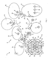
- reference numeral 9 has been generally identified a tyre manufacturing plant wherein the process for producing tyres according to the present invention is carried out.
- the tyre manufacturing plant 9 essentially comprises a building line 2 on which each tyre being processed is manufactured by assembling structural components of said tyre in a pre-established sequence, and a vulcanizing line 10 on which each tyre from the building line 2 is moulded and vulcanized within a respective mould 11.
- the different components of the tyre are made and/or assembled to form a green tyre with multiple carcass plies and corresponding multiple annular inserts.
- Said building line 2 essentially comprises a plurality of working stations 15, 16, 17, 18, 19, 20 disposed after each other along a manufacturing path, preferably in the form of a closed loop and represented, just as an indication, by arrows 12 in the drawing.
- the working stations 15, 16, 17, 18, 19, 20 lend themselves to operate simultaneously, each on at least one tyre being processed for assembling at least one of its structural components thereon.
- each tyre A, B, C, D, E, F are conveniently engaged on a support member, preferably consisting of a toroidal support the shape of which substantially matches the inner conformation of the tyre to be obtained.
- This toroidal support is preferably of the collapsible type or it is adapted to be divided into a plurality of sectors, so that it can be easily removed from the tyre when processing is over.
- Transport devices 22, 23, 24, 25, 26, 27, 28 operate on the building line 2 to sequentially transfer each of the tyres being processed A, B, C, D, E, F from one working station 15, 16, 17, 18, 19, 20, to the next working station, so as to cause sequential assembling of all tyre components, said tyre being then transferred to the vulcanizing line 10.
- these transport devices 22, 23, 24, 25, 26, 27, 28 comprise one or more robotized arms each of which is associated with at least one of the working stations 15, 16, 17, 18, 19, 20 and is adapted to operate on the individual toroidal supports A, B, C, D, E, F to carry out sequential transfer of each tyre being processed.
- a first robotized arm 22 which is possibly movable along a guide structure 21 and operates between the building line 2 and vulcanizing line 10, to pick up a finished tyre from the latter and transfer it to a first working station 15, where the tyre is removed from the respective toroidal support A through disassembling of said support.
- the toroidal support A is subsequently reassembled to be then transferred, still by the first robotized arm 22, to a first stand-by station 14 from which it will be picked up for subsequent use in the manufacture of a new tyre.
- a second robotized arm 23 lends itself to carry out transfer of the toroidal support F from the first stand-by station 14 to a second working station 16 where assembling of the first components for tyre construction is carried out.
- the assembling operation may, for example, involve coating of the outer surface of the toroidal support E with a thin layer of elastomer material impervious to air, usually called "liner", as well as application of optional elastomer bands close to the regions corresponding to the tyre beads, and/or formation of an additional coating layer of elastomer material, placed on top of the liner.
- each of the working stations 15, 16, 17, 18, 19, 20 is provided with one or more feeding devices adapted to supply the required base element for accomplishment of the corresponding structural component and operating in combination with application devices for applying the base element and/or the obtained structural component to the tyre being processed.
- the second robotized arm 23 lays down the toroidal support with the respective tyre which is being manufactured in a second stand-by station 14' that in the figure is occupied by toroidal support D, previously processed in the second station 16 itself.
- a third robotized arm 24 picks up the toroidal support D from the second stand-by station 14' to transfer it to a third working station 17.
- said third working station 17 comprises a working station 1, shown in more detail in figure 2 , adapted for assembling a carcass structure of a tyre, i.e. a structure comprising at least one carcass ply and one annular insert.
- the building line 2 includes one working station 1, however two or more working stations 1 may be provided in a building line 2 of a tyre manufacturing plant 9.
- Each working station 1 comprises two or more assembling apparatuses 3, 3', adapted for assembling at least a portion of the carcass structures of the tyres to be manufactured, and a first transferring device 13, adapted for transferring the toroidal support whereon the tyre is being built.
- said first transferring device 13 is adapted to perform three main functions:
- each working station 1 of the tyre building line 2 comprises a second transferring device 13' adapted to cooperate with the first transferring device 13.
- the first transferring device 13 comprises a robotized arm. More preferably also said second transferring device 13' comprises a robotized arm.
- the working station 1 may comprise a third transferring device adapted to move the toroidal support from the working station 1 to the building line 2.
- said third transferring device comprises a robotized arm.
- the working station 1 comprises at least one filler applying device 8, 8' adapted to lay a plurality of coils of a second elongated element on at least one radially inner side of the toroidal support in order to form a filling insert structure.
- the working station 1 comprises two filler applying devices 8, 8', as shown in fig. 1 .
- each of said two filler applying devices 8, 8' is placed downstream a relevant assembling apparatus 3, 3'.
- the assembling apparatus 3, 3' of the present embodiment of the invention comprises:
- the assembling apparatus 3, 3' may comprise two or more strip laying devices 4, two or more annular reinforcing insert laying devices 5 and/or two or more positioning devices 6.
- the positioning device 6 of the assembling apparatus 3, 3' comprises a sliding element which slides on suitable guides moving accordingly the toroidal support in different positions between the strip laying device 4 and the annular reinforcing insert laying device 5.
- the assembling apparatus 3, 3' of the preferred embodiment of the invention further comprises one or more cutting devices 7 adapted for suitably cutting said strip-like elements and comprising an upper cutting device and a lower cutting device.
- the fourth robotized arm 25 lays down the toroidal support on a third stand-by station 14" that in the figure is engaged by toroidal support F.
- a fifth robotized arm 26 picks up the toroidal support F from the third stand-by station 14" to carry it to a fourth working station 18 that in the example shown is occupied by toroidal support E.
- manufacture and assembling of the structural components adapted to define the so-called belt structure of the tyre are carried out.
- the fifth robotized arm 26 transfers the tyre being processed to a fifth working station 19 that in the example shown is occupied by toroidal support D.
- the toroidal support D is engaged by a sixth robotized arm 27 with the aid of which application of a tread band is carried out, said tread band being obtained by winding up an elastomer ribbon-like element in coils disposed consecutively in side by side relationship and superposed until achievement of a tread band of the desired conformation and thickness.
- the tyre is subsequently transferred to a sixth working station 20, occupied in this example by toroidal support C.
- the toroidal support C is engaged by a seventh robotized arm 28 causing appropriate handling of same in front of respective working apparatuses to carry out application of abrasion-resistant elements to the regions corresponding to the beads, as well as application of the sidewalls, which can be also obtained by winding up at least one elastomer band to form coils disposed in side by side and/or superposed relationship.
- the seventh robotized arm 28 lays down the manufactured tyre on an end stand-by station 14"', occupied, in this example, by toroidal support B, before transfer of the tyre itself to the vulcanizing line 10.
- Said vulcanizing line 10 advantageously comprises at least one series of vulcanization moulds 11 which are mounted on a turntable 30 to be driven in rotation in a step-by-step movement in the direction stated by arrow 31, so as to make the moulds carry out a closed-loop path along the vulcanizing line 10, sequentially carrying them, one after the other, to a loading-unloading station 32 of the tyres being processed.
- Said second step ii) comprises the sequentially building on the first toroidal support of a first toroidal carcass ply and a first pair of annular reinforcing inserts so as to associate each annular reinforcing insert to a respective radially internal edge of the first toroidal carcass ply.
- the first toroidal support is transferred to a second assembling apparatus 3' (step iii)) wherein subsequent step iv) is carried out: a second toroidal carcass ply and a second pair of annular reinforcing inserts are sequentially built on the first toroidal support, carrying the first toroidal carcass ply associated with the first pair of annular reinforcing inserts, so as to associate each annular reinforcing insert to a respective radially internal edge of the second toroidal carcass ply.
- a second toroidal support is transferred to the first assembling apparatus 3 (step v)) where a respective first toroidal carcass ply associated to a respective first pair of annular reinforcing inserts is built on said second toroidal support.
- the built tyres are subjected to a moulding and vulcanization step viii) which completes the tyre production process, as described above, in the vulcanizing line 10.
- the steps from i) to vii) are repeated at least once.
- the number of repetitions of said steps depends on the productivity needs.
- the process further comprises, between step ii) and step iv), the step of applying a first filler material on the first toroidal support carrying the first toroidal carcass ply associated with the first pair of annular reinforcing inserts.
- step vi) of completing the building of the tyre on the first toroidal support comprises applying a second filler material on the first toroidal support carrying the second toroidal carcass ply associated with the second pair of annular reinforcing inserts.
- the first filler material may be different from the second filler material. This may be used for example to obtain final tyres with specific performing features.
- At least one of said steps ii) and iv) is carried out by means of a positioning device 6 adapted to position the toroidal support in a position wherein a plurality of strip-like elements on side and crown portions of the toroidal support are laid, and in a position wherein a plurality of annular inserts on at least one radially inner side of the toroidal support are laid.
- At least one of said steps i), iii), v) is carried out by means of a first transferring device 13 adapted to transfer the toroidal support from a building line 2 containing a working station 1 comprising the first assembling apparatus 3 and the second assembling apparatus 3' into said working station 1 and viceversa and to transfer the toroidal support inside the working station 1, as mentioned above.
- steps i), iii), v) are carried out by means of a first transferring device 13 and the remaining steps are carried out by means of a second transferring device 13'.
- step iii) is carried out by means of a first transferring device 13 and steps i) and v) are carried out by means of a second transferring device 13'.
Landscapes
- Engineering & Computer Science (AREA)
- Mechanical Engineering (AREA)
- Tyre Moulding (AREA)
- Thermotherapy And Cooling Therapy Devices (AREA)
Claims (19)
- Verfahren zur Herstellung von Reifen, wobei die Reifen eine Karkassenstruktur aufweisen, die wenigstens zwei Karkassenlagen umfasst, wobei jede Karkassenlage mit wenigstens einem Paar von ringförmigen Verstärkungseinlagen assoziiert ist, wobei das Verfahren die folgenden Schritte umfasst:i) Übertragen eines ersten toroidförmigen Trägers an eine erste Montagevorrichtung (3);ii) In der ersten Montagevorrichtung (3), sequentielles Herstellen einer ersten toroidförmigen Karkassenlage und eines ersten Paars von ringförmigen Verstärkungseinlagen auf dem ersten toroidförmigen Träger, so dass jede ringförmige Verstärkungseinlage mit einer entsprechenden radialen Innenkante der ersten toroidförmigen Karkassenlage assoziiert ist;iii) Übertragen des ersten toroidförmigen Trägers an eine zweite Montagevorrichtung (3');iv) in der zweiten Montagevorrichtung (3'), sequentielles Herstellen auf dem ersten toroidförmigen Träger, der die erste toroidförmige Karkassenlage trägt, welche mit dem ersten Paar von ringförmigen Verstärkungseinlagen assoziiert ist, einer zweiten toroidförmigen Karkassenlage und eines zweiten Paars von ringförmigen Verstärkungseinlagen, so dass jede ringförmige Verstärkungseinlage mit einer entsprechenden radialen Innenkante der zweiten toroidförmigen Karkassenlage assoziiert ist;v) Übertragen eines zweiten toroidförmigen Trägers an die erste Montagevorrichtung (3), um eine entsprechende erste toroidförmige Karkassenlage darauf aufzubauen, welche mit einem entsprechenden ersten Paar von ringförmigen Verstärkungseinlagen assoziiert ist;vi) Abschließen des Herstellens des Reifens auf dem ersten toroidförmigen Träger;vii) Wiederholen der Schritte iv) und vi) auf dem zweiten toroidförmigen Träger;viii) Ausformen und Vulkanisieren der hergestellten Reifen;wobei der Schritt v) des Übertragens des zweiten toroidförmigen Trägers zur Montagevorrichtung (3') ausgeführt wird, wenn der erste toroidförmige Träger in der zweiten Montagevorrichtung (3') während des Schritts iv) bearbeitet wird.
- Verfahren nach Anspruch 1, das zwischen Schritt ii) und Schritt iv) ferner den Schritt des Aufbringens eines ersten Füllmaterials auf den ersten toroidförmigen Träger umfasst, der die erste toroidförmige Karkassenlage trägt, welche mit dem ersten Paar von ringförmigen Verstärkungseinlagen assoziiert ist.
- Verfahren nach einem der vorhergehenden Ansprüche, bei dem der Schritt vi) das Aufbringen eines zweiten Füllmaterials auf den ersten toroidförmigen Träger umfasst, der die zweite toroidförmige Karkassenlage trägt, welche mit dem zweiten Paar von ringförmigen Verstärkungseinlagen assoziiert ist.
- Verfahren nach einem der vorhergehenden Ansprüche, bei dem der Schritt ii) und/oder iv) mittels einer Positionierungseinrichtung (6) ausgeführt wird, welche ausgelegt ist, um den toroidförmigen Träger in eine Position zu bringen, wo eine Mehrzahl von streifenförmigen Elementen an Seiten- und Kronenabschnitten des toroidförmigen Trägers aufgebracht werden, und in eine Position, wo eine Mehrzahl von ringförmigen Einlagen auf wenigstens eine radiale Innenseite des toroidförmigen Trägers aufgebracht wird.
- Verfahren nach einem der vorhergehenden Ansprüche, bei dem wenigstens einer der Schritte i), iii), v) mittels einer ersten Übertragungseinrichtung (13) ausgeführt wird, die ausgelegt ist, um den toroidförmigen Träger von einer Montagelinie (2), welche eine Arbeitstation (1) enthält, welche die erste Montagevorrichtung (3) und die zweite Montagevorrichtung (3') umfasst, in die Arbeitsstation (1) und umgekehrt zu übertragen und um den toroidförmigen Träger in der Arbeitsstation (1) zu übertragen.
- Verfahren nach einem der vorhergehenden Ansprüche, bei dem der Schritt iii) mittels einer ersten Übertragungseinrichtung (13) ausgeführt wird und die Schritte i) und v) mittels einer zweiten Übertragungseinrichtung (13') ausgeführt werden.
- Verfahren nach Anspruch 3, bei dem das erste Füllmaterial sich von dem zweiten Füllmaterial unterscheidet.
- Reifenmontagelinie (2), welche wenigstens eine Arbeitsstation (1) zur Montage einer Karkassenstruktur enthält, wobei die Arbeitsstation (1) umfasst:wenigstens zwei Montagevorrichtungen (3, 3') der Karkassenstruktur, wobei jede Montagevorrichtung (3, 3') enthält:wenigstens eine Streifenschichtungseinrichtung (4), die ausgelegt ist, um eine Mehrzahl von streifenförmigen Elementen auf Seiten- und Kronenabschnitten eines toroidförmigen Trägers aufzubringen, um eine Karkassenlage auszubilden;wenigstens eine Schichtungseinrichtung der ringförmigen Verstärkungseinlage (5), welche ausgelegt ist, um eine Mehrzahl von Wicklungen eines ersten länglichen Elements auf wenigstens eine radiale Innenseite des toroidförmigen Trägers aufzubringen, um eine ringförmige Verstärkungseinlage auszubilden;wenigstens eine Übertragungseinrichtung (13, 13') zum Ausführen wenigstens eines Übertragungsschritts des toroidförmigen Trägers, ausgewählt aus:(i) einem Übertragungssahritt von der Montagelinie (2) in die Arbeitsstation (1);(ii) einem Übertragungsschritt in der Arbeitstation (1);(iii) einem Übertragungsschritt von der Arbeitsstation (1) zur Montagelinie (2).
- Reifenmontagelinie (2) nach Anspruch 8, bei der jede der Montagevorrichtungen (3, 3') wenigstens eine Positionierungseinrichtung (6) umfasst, die ausgelegt ist, um den toroidförmigen Träger an der Streifenschichtungseinrichtung (4) oder der Schichtungseinrichtung der ringförmigen Verstärkungseinlage (5) zu positionieren.
- Reifenmontagelinie (2) nach Anspruch 8 oder 9, bei der die Arbeitstation (1) zwei Übertragungseinrichtungen (13, 13') umfasst, die ausgelegt sind, um zusammenzuwirken.
- Reifenmontagelinie (2) nach einem der Ansprüche 8 bis 10, bei der eine erste Übertragungseinrichtung (13) einen Roboterarm umfasst.
- Reifenmontagelinie (2) nach Anspruch 10, bei der eine zweite Übertragungseinrichtung (13') einen Roboterarm umfasst.
- Reifenmontagelinie (2) nach einem der Ansprüche 8 bis 12, bei der die Arbeitstation (1) wenigstens eine Fülleraufbringeinrichtung (8, 8') umfasst, die ausgelegt ist, um eine Mehrzahl von Wicklungen aus einem zweiten länglichen Element auf wenigstens eine radiale Innenseite des toroidförmigen Trägers aufzubringen, um eine füllende Einlagenstruktur auszubilden.
- Reifenmontagelinie (2) nach Anspruch 13, bei der die Arbeitstation (1) zwei Fülleraufbringeinrichtungen (8, 8') umfasst.
- Montagelinie (3, 3') zur Montage wenigstens eines Abschnitts einer Karkassenstruktur, umfassend:wenigstens eine Streifenschichtungseinrichtung (4), die ausgelegt ist, um eine Mehrzahl von streifenförmigen Elementen auf Seiten- und Kronenabschnitte eines toroidförmigen Trägers aufzubringen, um eine Karkassenlage auszubilden;wenigstens eine Schichtungseinrichtung der ringförmigen Verstärkungseinlage (5) die ausgelegt ist, um eine Mehrzahl von Wicklungen eines ersten länglichen Elements auf wenigstens eine radiale Innenseite des toroidförmigen Trägers aufzubringen, um eine ringförmige Verstärkungseinlage auszubilden;wenigstens eine Positionierungseinrichtung (6), die ausgelegt ist, um den toroidförmigen Träger abwechselnd an der Streifenschichtungseinrichtung (4) und der Schichtungseinrichtung der ringförmigen Verstärkungseinlagen (5) zu positionieren,wobei die wenigstens eine Streifenschichtungseinrichtung (4), die wenigstens eine Schichtungseinrichtung der ringförmigen Verstärkungseinlage (5) und die wenigstens eine Positionierungseinrichtung (6) in derselben Montagevorrichtung (3, 3') integriert sind.
- Montagevorrichtung (3, 3') nach Anspruch 15, bei der die Positionierungseinrichtung (6) ein Gleitelement umfasst.
- Montagevorrichtung (3, 3') nach Anspruch 15 oder 16, die ferner wenigstens eine Schneideinrichtung (7) umfasst, die ausgelegt ist, um die streifenförmigen Elemente zu schneiden.
- Montagevorrichtung (3, 3') nach Anspruch 17, bei der die Schneideinrichtung (7) eine obere Schneideinrichtung und eine untere Schneideinrichtung umfasst.
- Reifenherstellungsanlage (9), welche eine Reifenmontagelinie (2) nach einem der Ansprüche 8 bis 14 und eine Vulkanisierungslinie (10) umfasst.
Applications Claiming Priority (1)
| Application Number | Priority Date | Filing Date | Title |
|---|---|---|---|
| PCT/EP2006/009872 WO2008043382A1 (en) | 2006-10-12 | 2006-10-12 | Producing process of a pneumatic tyre and relevant building line and assembling apparatus |
Publications (3)
| Publication Number | Publication Date |
|---|---|
| EP2076376A1 EP2076376A1 (de) | 2009-07-08 |
| EP2076376B1 EP2076376B1 (de) | 2011-01-05 |
| EP2076376B9 true EP2076376B9 (de) | 2011-11-02 |
Family
ID=38007915
Family Applications (1)
| Application Number | Title | Priority Date | Filing Date |
|---|---|---|---|
| EP06806229A Active EP2076376B9 (de) | 2006-10-12 | 2006-10-12 | Verfahren zur herstellung eines luftreifens und entsprechende aufbaulinie und montagevorrichtung |
Country Status (7)
| Country | Link |
|---|---|
| US (1) | US20100032864A1 (de) |
| EP (1) | EP2076376B9 (de) |
| CN (1) | CN101522403B (de) |
| AT (1) | ATE494134T1 (de) |
| BR (1) | BRPI0622026B1 (de) |
| DE (1) | DE602006019507D1 (de) |
| WO (1) | WO2008043382A1 (de) |
Families Citing this family (11)
| Publication number | Priority date | Publication date | Assignee | Title |
|---|---|---|---|---|
| WO2009157028A1 (en) | 2008-06-27 | 2009-12-30 | Pirelli Tyre S.P.A. | Process and plant for building tyres for vehicle wheels |
| BR112012015130B1 (pt) | 2009-12-21 | 2020-04-07 | Pirelli | processo para construir pneus, e, instalação para construir pneus para rodas de veículos |
| US8662122B2 (en) * | 2010-05-14 | 2014-03-04 | The Goodyear Tire & Rubber Company | System for non-pneumatic support of a vehicle |
| CN102892574B (zh) * | 2010-05-28 | 2015-12-16 | 倍耐力轮胎股份公司 | 在构建用于车轮的轮胎时控制成型鼓的管理的方法以及用于生产用于车轮的轮胎的设备 |
| ITMI20111320A1 (it) * | 2011-07-15 | 2013-01-16 | Pirelli | Metodo, processo e apparato per confezionare pneumatici per ruote di veicoli |
| ITMI20112370A1 (it) * | 2011-12-23 | 2013-06-24 | Pirelli | Processo e impianto di confezionamento di pneumatici per ruote di veicoli |
| ITMI20122214A1 (it) | 2012-12-21 | 2014-06-22 | Pirelli | Metodo e impianto per confezionare pneumatici per ruote di veicoli |
| CN106536174B (zh) | 2014-06-20 | 2021-09-03 | 倍耐力轮胎股份公司 | 用于构建用于车辆车轮的生轮胎的工艺和设备 |
| WO2016075576A1 (en) * | 2014-11-14 | 2016-05-19 | Pirelli Tyre S.P.A. | Process and plant for building tyres |
| JP7260028B1 (ja) | 2022-04-01 | 2023-04-18 | 横浜ゴム株式会社 | タイヤの製造方法および製造システム |
| JP7323835B1 (ja) | 2022-04-01 | 2023-08-09 | 横浜ゴム株式会社 | タイヤの製造方法および製造システム |
Family Cites Families (9)
| Publication number | Priority date | Publication date | Assignee | Title |
|---|---|---|---|---|
| US1818955A (en) * | 1929-06-28 | 1931-08-11 | Goodyear Tire & Rubber | Method of and apparatus for manufacturing pneumatic tires |
| DE2134904B1 (de) * | 1971-07-13 | 1973-01-04 | Leonhard Herbert Maschinenfabrik, 6000 Bergen-Enkheim | Einrichtung zum Aufbauen und Formen eines Rohlings für Gürtelreifen |
| US4134783A (en) * | 1976-06-16 | 1979-01-16 | The Goodyear Tire & Rubber Company | Tire building system |
| US6945295B2 (en) * | 2000-01-28 | 2005-09-20 | Pirelli Pneumatici S.P.A. | Tire for a vehicle wheel comprising a particular carcass structure |
| DE60113405T2 (de) * | 2000-05-26 | 2006-06-22 | Pirelli Pneumatici S.P.A. | Anlage zur simultanen herstellung von unterschiedlichen luftreifentypen |
| DE60210444T2 (de) * | 2001-05-29 | 2007-04-12 | Pirelli Pneumatici S.P.A. | Automatischer prozess und automatische anlage zur reifenherstellung |
| WO2003062113A1 (en) * | 2001-12-21 | 2003-07-31 | Gianni De Paoli | Dynamic storage unit for structural components of a tyre |
| US20040238102A1 (en) * | 2003-05-30 | 2004-12-02 | Jean-Claude Girard | Method for manufacturing tires on a flexible manufacturing system |
| US7195047B2 (en) * | 2003-12-11 | 2007-03-27 | The Goodyear Tire And Rubber Company | Tire manufacturing module and method of manufacturing tires |
-
2006
- 2006-10-12 BR BRPI0622026-6A patent/BRPI0622026B1/pt active IP Right Grant
- 2006-10-12 CN CN2006800560810A patent/CN101522403B/zh active Active
- 2006-10-12 EP EP06806229A patent/EP2076376B9/de active Active
- 2006-10-12 DE DE602006019507T patent/DE602006019507D1/de active Active
- 2006-10-12 WO PCT/EP2006/009872 patent/WO2008043382A1/en not_active Ceased
- 2006-10-12 US US12/311,432 patent/US20100032864A1/en not_active Abandoned
- 2006-10-12 AT AT06806229T patent/ATE494134T1/de not_active IP Right Cessation
Also Published As
| Publication number | Publication date |
|---|---|
| EP2076376A1 (de) | 2009-07-08 |
| CN101522403A (zh) | 2009-09-02 |
| DE602006019507D1 (de) | 2011-02-17 |
| ATE494134T1 (de) | 2011-01-15 |
| EP2076376B1 (de) | 2011-01-05 |
| BRPI0622026B1 (pt) | 2018-02-14 |
| WO2008043382A1 (en) | 2008-04-17 |
| BRPI0622026A2 (pt) | 2014-04-22 |
| US20100032864A1 (en) | 2010-02-11 |
| CN101522403B (zh) | 2012-08-29 |
Similar Documents
| Publication | Publication Date | Title |
|---|---|---|
| EP2258541B1 (de) | Verfahren und anlage zur herstellung von fahrzeugreifen | |
| EP1224074B1 (de) | Verfahren und vorrichtung zur herstellung von unterschiedlichen reifentypen | |
| US20110290403A1 (en) | Process and plant for building green tyres for vehicle wheels | |
| US20190152177A1 (en) | Process and plant for building green tyres for vehicle wheels | |
| US11090890B2 (en) | Process for building tyres for vehicle wheels | |
| US11993039B2 (en) | Plant for building green tyres for vehicle wheels | |
| EP2234799B1 (de) | Verfahren und Anlage zum Bau von Reifen für Fahrzeugräder | |
| US7005023B2 (en) | Method of manufacturing tires | |
| EP2076376B1 (de) | Verfahren zur herstellung eines luftreifens und entsprechende aufbaulinie und montagevorrichtung | |
| CN101870175B (zh) | 用于生产车轮用轮胎的工艺和设备 | |
| CN104797411A (zh) | 用于制造车轮轮胎的方法和设备 | |
| CN101193740A (zh) | 车轮轮胎的硫化方法和装置 |
Legal Events
| Date | Code | Title | Description |
|---|---|---|---|
| PUAI | Public reference made under article 153(3) epc to a published international application that has entered the european phase |
Free format text: ORIGINAL CODE: 0009012 |
|
| 17P | Request for examination filed |
Effective date: 20090319 |
|
| AK | Designated contracting states |
Kind code of ref document: A1 Designated state(s): AT BE BG CH CY CZ DE DK EE ES FI FR GB GR HU IE IS IT LI LT LU LV MC NL PL PT RO SE SI SK TR |
|
| 17Q | First examination report despatched |
Effective date: 20090902 |
|
| GRAP | Despatch of communication of intention to grant a patent |
Free format text: ORIGINAL CODE: EPIDOSNIGR1 |
|
| GRAS | Grant fee paid |
Free format text: ORIGINAL CODE: EPIDOSNIGR3 |
|
| GRAA | (expected) grant |
Free format text: ORIGINAL CODE: 0009210 |
|
| AK | Designated contracting states |
Kind code of ref document: B1 Designated state(s): AT BE BG CH CY CZ DE DK EE ES FI FR GB GR HU IE IS IT LI LT LU LV MC NL PL PT RO SE SI SK TR |
|
| REG | Reference to a national code |
Ref country code: GB Ref legal event code: FG4D |
|
| REG | Reference to a national code |
Ref country code: CH Ref legal event code: EP |
|
| REG | Reference to a national code |
Ref country code: IE Ref legal event code: FG4D |
|
| REF | Corresponds to: |
Ref document number: 602006019507 Country of ref document: DE Date of ref document: 20110217 Kind code of ref document: P |
|
| REG | Reference to a national code |
Ref country code: DE Ref legal event code: R096 Ref document number: 602006019507 Country of ref document: DE Effective date: 20110217 |
|
| REG | Reference to a national code |
Ref country code: RO Ref legal event code: EPE |
|
| REG | Reference to a national code |
Ref country code: NL Ref legal event code: VDEP Effective date: 20110105 |
|
| PG25 | Lapsed in a contracting state [announced via postgrant information from national office to epo] |
Ref country code: SI Free format text: LAPSE BECAUSE OF FAILURE TO SUBMIT A TRANSLATION OF THE DESCRIPTION OR TO PAY THE FEE WITHIN THE PRESCRIBED TIME-LIMIT Effective date: 20110105 |
|
| LTIE | Lt: invalidation of european patent or patent extension |
Effective date: 20110105 |
|
| PG25 | Lapsed in a contracting state [announced via postgrant information from national office to epo] |
Ref country code: ES Free format text: LAPSE BECAUSE OF FAILURE TO SUBMIT A TRANSLATION OF THE DESCRIPTION OR TO PAY THE FEE WITHIN THE PRESCRIBED TIME-LIMIT Effective date: 20110416 Ref country code: IS Free format text: LAPSE BECAUSE OF FAILURE TO SUBMIT A TRANSLATION OF THE DESCRIPTION OR TO PAY THE FEE WITHIN THE PRESCRIBED TIME-LIMIT Effective date: 20110505 Ref country code: PT Free format text: LAPSE BECAUSE OF FAILURE TO SUBMIT A TRANSLATION OF THE DESCRIPTION OR TO PAY THE FEE WITHIN THE PRESCRIBED TIME-LIMIT Effective date: 20110505 Ref country code: LV Free format text: LAPSE BECAUSE OF FAILURE TO SUBMIT A TRANSLATION OF THE DESCRIPTION OR TO PAY THE FEE WITHIN THE PRESCRIBED TIME-LIMIT Effective date: 20110105 Ref country code: LT Free format text: LAPSE BECAUSE OF FAILURE TO SUBMIT A TRANSLATION OF THE DESCRIPTION OR TO PAY THE FEE WITHIN THE PRESCRIBED TIME-LIMIT Effective date: 20110105 Ref country code: GR Free format text: LAPSE BECAUSE OF FAILURE TO SUBMIT A TRANSLATION OF THE DESCRIPTION OR TO PAY THE FEE WITHIN THE PRESCRIBED TIME-LIMIT Effective date: 20110406 Ref country code: SE Free format text: LAPSE BECAUSE OF FAILURE TO SUBMIT A TRANSLATION OF THE DESCRIPTION OR TO PAY THE FEE WITHIN THE PRESCRIBED TIME-LIMIT Effective date: 20110105 |
|
| PG25 | Lapsed in a contracting state [announced via postgrant information from national office to epo] |
Ref country code: NL Free format text: LAPSE BECAUSE OF FAILURE TO SUBMIT A TRANSLATION OF THE DESCRIPTION OR TO PAY THE FEE WITHIN THE PRESCRIBED TIME-LIMIT Effective date: 20110105 Ref country code: AT Free format text: LAPSE BECAUSE OF FAILURE TO SUBMIT A TRANSLATION OF THE DESCRIPTION OR TO PAY THE FEE WITHIN THE PRESCRIBED TIME-LIMIT Effective date: 20110105 Ref country code: FI Free format text: LAPSE BECAUSE OF FAILURE TO SUBMIT A TRANSLATION OF THE DESCRIPTION OR TO PAY THE FEE WITHIN THE PRESCRIBED TIME-LIMIT Effective date: 20110105 Ref country code: CY Free format text: LAPSE BECAUSE OF FAILURE TO SUBMIT A TRANSLATION OF THE DESCRIPTION OR TO PAY THE FEE WITHIN THE PRESCRIBED TIME-LIMIT Effective date: 20110105 Ref country code: BG Free format text: LAPSE BECAUSE OF FAILURE TO SUBMIT A TRANSLATION OF THE DESCRIPTION OR TO PAY THE FEE WITHIN THE PRESCRIBED TIME-LIMIT Effective date: 20110405 Ref country code: BE Free format text: LAPSE BECAUSE OF FAILURE TO SUBMIT A TRANSLATION OF THE DESCRIPTION OR TO PAY THE FEE WITHIN THE PRESCRIBED TIME-LIMIT Effective date: 20110105 Ref country code: PL Free format text: LAPSE BECAUSE OF FAILURE TO SUBMIT A TRANSLATION OF THE DESCRIPTION OR TO PAY THE FEE WITHIN THE PRESCRIBED TIME-LIMIT Effective date: 20110105 |
|
| PG25 | Lapsed in a contracting state [announced via postgrant information from national office to epo] |
Ref country code: EE Free format text: LAPSE BECAUSE OF FAILURE TO SUBMIT A TRANSLATION OF THE DESCRIPTION OR TO PAY THE FEE WITHIN THE PRESCRIBED TIME-LIMIT Effective date: 20110105 Ref country code: DK Free format text: LAPSE BECAUSE OF FAILURE TO SUBMIT A TRANSLATION OF THE DESCRIPTION OR TO PAY THE FEE WITHIN THE PRESCRIBED TIME-LIMIT Effective date: 20110105 |
|
| PLBE | No opposition filed within time limit |
Free format text: ORIGINAL CODE: 0009261 |
|
| STAA | Information on the status of an ep patent application or granted ep patent |
Free format text: STATUS: NO OPPOSITION FILED WITHIN TIME LIMIT |
|
| PG25 | Lapsed in a contracting state [announced via postgrant information from national office to epo] |
Ref country code: CZ Free format text: LAPSE BECAUSE OF FAILURE TO SUBMIT A TRANSLATION OF THE DESCRIPTION OR TO PAY THE FEE WITHIN THE PRESCRIBED TIME-LIMIT Effective date: 20110105 Ref country code: SK Free format text: LAPSE BECAUSE OF FAILURE TO SUBMIT A TRANSLATION OF THE DESCRIPTION OR TO PAY THE FEE WITHIN THE PRESCRIBED TIME-LIMIT Effective date: 20110105 |
|
| 26N | No opposition filed |
Effective date: 20111006 |
|
| REG | Reference to a national code |
Ref country code: DE Ref legal event code: R097 Ref document number: 602006019507 Country of ref document: DE Effective date: 20111006 |
|
| PG25 | Lapsed in a contracting state [announced via postgrant information from national office to epo] |
Ref country code: MC Free format text: LAPSE BECAUSE OF NON-PAYMENT OF DUE FEES Effective date: 20111031 |
|
| REG | Reference to a national code |
Ref country code: CH Ref legal event code: PL |
|
| PG25 | Lapsed in a contracting state [announced via postgrant information from national office to epo] |
Ref country code: CH Free format text: LAPSE BECAUSE OF NON-PAYMENT OF DUE FEES Effective date: 20111031 Ref country code: LI Free format text: LAPSE BECAUSE OF NON-PAYMENT OF DUE FEES Effective date: 20111031 |
|
| REG | Reference to a national code |
Ref country code: IE Ref legal event code: MM4A |
|
| PG25 | Lapsed in a contracting state [announced via postgrant information from national office to epo] |
Ref country code: IE Free format text: LAPSE BECAUSE OF NON-PAYMENT OF DUE FEES Effective date: 20111012 |
|
| PG25 | Lapsed in a contracting state [announced via postgrant information from national office to epo] |
Ref country code: LU Free format text: LAPSE BECAUSE OF NON-PAYMENT OF DUE FEES Effective date: 20111012 |
|
| PG25 | Lapsed in a contracting state [announced via postgrant information from national office to epo] |
Ref country code: HU Free format text: LAPSE BECAUSE OF FAILURE TO SUBMIT A TRANSLATION OF THE DESCRIPTION OR TO PAY THE FEE WITHIN THE PRESCRIBED TIME-LIMIT Effective date: 20110105 |
|
| REG | Reference to a national code |
Ref country code: FR Ref legal event code: PLFP Year of fee payment: 10 |
|
| REG | Reference to a national code |
Ref country code: FR Ref legal event code: PLFP Year of fee payment: 11 |
|
| REG | Reference to a national code |
Ref country code: FR Ref legal event code: PLFP Year of fee payment: 12 |
|
| REG | Reference to a national code |
Ref country code: FR Ref legal event code: PLFP Year of fee payment: 13 |
|
| PGFP | Annual fee paid to national office [announced via postgrant information from national office to epo] |
Ref country code: TR Payment date: 20250925 Year of fee payment: 20 |
|
| PGFP | Annual fee paid to national office [announced via postgrant information from national office to epo] |
Ref country code: RO Payment date: 20250925 Year of fee payment: 20 |
|
| PGFP | Annual fee paid to national office [announced via postgrant information from national office to epo] |
Ref country code: DE Payment date: 20251029 Year of fee payment: 20 |
|
| PGFP | Annual fee paid to national office [announced via postgrant information from national office to epo] |
Ref country code: GB Payment date: 20251027 Year of fee payment: 20 |
|
| PGFP | Annual fee paid to national office [announced via postgrant information from national office to epo] |
Ref country code: IT Payment date: 20251021 Year of fee payment: 20 |
|
| PGFP | Annual fee paid to national office [announced via postgrant information from national office to epo] |
Ref country code: FR Payment date: 20251027 Year of fee payment: 20 |