EP2076458B1 - Einrichtung zur überwachung einer förderanlage - Google Patents
Einrichtung zur überwachung einer förderanlage Download PDFInfo
- Publication number
- EP2076458B1 EP2076458B1 EP07787220.8A EP07787220A EP2076458B1 EP 2076458 B1 EP2076458 B1 EP 2076458B1 EP 07787220 A EP07787220 A EP 07787220A EP 2076458 B1 EP2076458 B1 EP 2076458B1
- Authority
- EP
- European Patent Office
- Prior art keywords
- conveyor belt
- light
- projector
- structured light
- running
- Prior art date
- Legal status (The legal status is an assumption and is not a legal conclusion. Google has not performed a legal analysis and makes no representation as to the accuracy of the status listed.)
- Not-in-force
Links
Images
Classifications
-
- B—PERFORMING OPERATIONS; TRANSPORTING
- B65—CONVEYING; PACKING; STORING; HANDLING THIN OR FILAMENTARY MATERIAL
- B65G—TRANSPORT OR STORAGE DEVICES, e.g. CONVEYORS FOR LOADING OR TIPPING, SHOP CONVEYOR SYSTEMS OR PNEUMATIC TUBE CONVEYORS
- B65G43/00—Control devices, e.g. for safety, warning or fault-correcting
- B65G43/02—Control devices, e.g. for safety, warning or fault-correcting detecting dangerous physical condition of load carriers, e.g. for interrupting the drive in the event of overheating
-
- G—PHYSICS
- G01—MEASURING; TESTING
- G01B—MEASURING LENGTH, THICKNESS OR SIMILAR LINEAR DIMENSIONS; MEASURING ANGLES; MEASURING AREAS; MEASURING IRREGULARITIES OF SURFACES OR CONTOURS
- G01B11/00—Measuring arrangements characterised by the use of optical techniques
- G01B11/24—Measuring arrangements characterised by the use of optical techniques for measuring contours or curvatures
- G01B11/25—Measuring arrangements characterised by the use of optical techniques for measuring contours or curvatures by projecting a pattern, e.g. one or more lines, moiré fringes on the object
- G01B11/2518—Projection by scanning of the object
- G01B11/2522—Projection by scanning of the object the position of the object changing and being recorded
-
- B—PERFORMING OPERATIONS; TRANSPORTING
- B65—CONVEYING; PACKING; STORING; HANDLING THIN OR FILAMENTARY MATERIAL
- B65G—TRANSPORT OR STORAGE DEVICES, e.g. CONVEYORS FOR LOADING OR TIPPING, SHOP CONVEYOR SYSTEMS OR PNEUMATIC TUBE CONVEYORS
- B65G2203/00—Indexing code relating to control or detection of the articles or the load carriers during conveying
- B65G2203/04—Detection means
- B65G2203/041—Camera
-
- B—PERFORMING OPERATIONS; TRANSPORTING
- B65—CONVEYING; PACKING; STORING; HANDLING THIN OR FILAMENTARY MATERIAL
- B65G—TRANSPORT OR STORAGE DEVICES, e.g. CONVEYORS FOR LOADING OR TIPPING, SHOP CONVEYOR SYSTEMS OR PNEUMATIC TUBE CONVEYORS
- B65G2203/00—Indexing code relating to control or detection of the articles or the load carriers during conveying
- B65G2203/04—Detection means
- B65G2203/042—Sensors
- B65G2203/044—Optical
Definitions
- the invention relates to a device for monitoring a conveyor system according to the preamble of claim 1.
- the DE 100 48 552 A1 relates to a device for monitoring a conveyor system, wherein an area in which no material transport takes place, is provided with an optoelectronic system which optically detects and reports damage to the conveyor belt while observing the support side.
- the DE 100 63 293 A1 relates to a method and an apparatus for multi-channel inspection of surfaces in the run.
- a number of parallel short lines are projected onto the surface to be inspected by a structured light projector.
- the short projected lines and the examination line of the camera are perpendicular to each other and intersect each other.
- a line scan camera is used as image capture device, so that the examination lines of the line scan camera run across the width of the object to be examined. Since the projected lines of the projector are perpendicular to the examination curves, the structured light runs in the direction of movement of the object to be examined.
- the object of the invention is to detect the depth of conveyor belt damage in addition to the areal (two-dimensional) damage detection in order to draw conclusions about the severity of the damage can.
- the invention will now be explained with reference to an embodiment with reference to a schematic drawing.
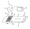
- the single figure shows a conveyor system with projector, which throws a structured light on the support side of a conveyor belt.
- the conveyor 1 comprises a conveyor belt 2 made of elastomeric material having a support side 3 and running side 4.
- the opto-electronic system 5 optically detects the support side of the conveyor belt.
- the conveyor system 1 further comprises a projector 7 which throws a structured light 8 onto a material-free zone of the conveyor belt 2.
- the structured light is formed here in the form of pararallel light strips 9 with light and dark zones or different color zones.
- the projector is adjusted so that the structured light (light stripe) in its main extension direction X extends transversely to the conveying direction Y and also detects the entire conveyor belt width A.
- the structured light (light strip) has an extension dimension B which occupies at least half the conveyor belt width A.
- the parallel strips of light assume an unchanged structural constellation on an undamaged conveyor belt on the belt surface (in this case the support side).
- the patterned light 8 encounters an anomaly caused by damage 10, it will curve according to the depth or height of the anomaly.
- the light (light stripe) is offset laterally.
- the opto-electronic system 5 in particular in the form of a digital camera system, recognizes this structural change by offset.
- the process computer 6 processes the trigonometric relation and calculates the depth of the damage 10 by triangulation.
- the opto-electronic system 5 is programmed so that a warning signal and / or the automatic shutdown of the conveyor 1 is triggered, for example, if the depth of the damage exceeds 10 two millimeters.
- the opto-electronic system 5 and the projector 7 thereby capture the carrying side in the region of a material-free drum, for example in the region of the reversing drum.
- the previously known conveyor systems which include an optoelectronic system according to the cited prior art, without complicated additional measures with the projector, which emits the structured light, are equipped.
- the technology can be used according to WO 2005/023668 A1 can be applied by integrating the projector into the plant design disclosed in this document.
Landscapes
- Engineering & Computer Science (AREA)
- Computer Vision & Pattern Recognition (AREA)
- Physics & Mathematics (AREA)
- General Physics & Mathematics (AREA)
- Control Of Conveyors (AREA)
- Length Measuring Devices By Optical Means (AREA)
Description
- Die Erfindung betrifft eine Einrichtung zur Überwachung einer Förderanlage gemäß dem Oberbegriff des Anspruchs 1.
- Da Fördergurte in Minenanlagen oft die wichtigsten Teile der Anlage darstellen, deren Versagen häufig einen kompletten Produktionsstillstand bedeuten kann, werden Verfahren zur automatischen, kontinuierlichen Überwachung der Fördergurte verlangt. Neben den bekannten Verfahren der Schlitzüberwachung (
DE 44 44 264 C2 ) und der Verbindungsüberwachung (EP 1 053 447 B1 ) sind auch Methoden zur Überwachung der gesamten Gurtoberfläche gefragt, um Verschleißschäden oder oberflächliche Beaufschlagungsschäden und deren Weiterentwicklung während des Betriebes zu erkennen und bei Erreichen eines kritischen Zustandes den Gurt still zu setzen, um rechtzeitig Reparaturmaßnahmen einzuleiten. - Zur Erreichung dieses Zieles wird der Einsatz opto-elektronischer Systeme, insbesondere in Form elektronischer Kamerasysteme (Zeilenkamera oder Flächenkamera), vorgeschlagen, wobei insbesondere auf folgenden Stand der Technik verwiesen wird:
-
DE 42 40 094 A1 -
DE 100 29 545 A1 -
DE 101 00 813 A1 -
DE 101 29 091 A1 -
DE 101 40 920 A1 -
EP 1 187 781 B1 -
EP 1 222 126 B1 - Diese opto-elektronischen Systeme generieren Bilder von der zu überwachenden Gurtoberfläche, insbesondere die der Tragseite, verbunden mit einer automatischen Auswertung und Beurteilung der so gewonnenen Bildinformation. Um eine wirksame automatische Überwachung des gesamten Gurtes durchführen zu können, ist ferner die millimetergenaue Lokalisierung jeder beliebigen Stelle des Gurtes entwickelt worden, da nur so mit Hilfe automatischer Bildverarbeitungssoftware eine Verfolgung der Schadensentwicklung über einen gewissen Zeitraum bewerkstelligt werden kann (
WO 2005/023688A1 ). - Aus der Offenlegungschrift
DE 42 40 094 A1 ist eine Einrichtung zur Überwachung einer Förderanlage bekannt, wo zusätzlich zu dem opto-elektronischen System ein Projektor vorhanden ist, der Licht auf das Fördermaterial wirft. Zielsetzung ist es, den Materialstrom zu überwachen. Erfasst wir dabei der Oberkantenverlauf des Fördermaterials. - Die
DE 100 48 552 A1 betrifft eine Einrichtung zur Überwachung einer Förderanlage, wobei ein Bereich, in dem keine Materialbeförderung stattfindet, mit einem optoelektronischen System versehen ist, welches unter Beobachtung der Tragseite eine Beschädigung des Fördergurtes optisch erfasst und meldet. - Die
DE 100 63 293 A1 betrifft ein Verfahren und eine Vorrichtung zur mehrkanaligen Inspektion von Oberflächen im Durchlauf. Hierzu wird durch einen Projektor für strukturiertes Licht eine Anzahl von parallelen kurzen Linien auf die zu inspizierende Oberfläche projiziert. Die kurzen projizierten Linien und die Untersuchungslinie der Kamera stehen senkrecht zueinander und schneiden einander. Es wird eine Zeilenkamera als Bilderfassungsvorrichtung verwendet, so dass die Untersuchungslinien der Zeilenkamera über die Breite des zu untersuchenden Gegenstandes verlaufen. Da die projizierten Linien des Projektors senkrecht zu den Untersuchungskennlinien stehen, verläuft das strukturierte Licht in Bewegungsrichtung des zu untersuchenden Objekts. - Im Rahmen einer Weiterentwicklung unter Einsatz eines opto-elektronischen Systems in Verbindung mit einem Projektor besteht die Aufgabe der Erfindung darin, neben der flächenmäßigen (zweidimensionalen) Schadenserfassung auch die Tiefe von Fördergurtschäden zu erfassen, um Rückschlüsse auf die Schwere der Beschädigung ziehen zu können.
- Gelöst wird diese Aufgabe durch eine Vorrichtung mit den Merkmalen gemäß Patentanspruch 1.
- Zweckmäßige Ausgestaltungen der neuen Einrichtung sind in den Patentansprüchen 2 bis 7 genannt.
- Die Erfindung wird nun anhand eines Ausführungsbeispieles unter Bezugnahme auf eine schematische Zeichnung erläutert. Die einzige Figur zeigt dabei eine Förderanlage mit Projektor, der ein strukturiertes Licht auf die Tragseite eines Fördergurtes wirft.
- Nach der einzigen Figur umfasst die Förderanlage 1 einen Fördergurt 2 aus elastomerem Werkstoff mit einer Tragseite 3 und Laufseite 4. Das opto-elektronische System 5 erfasst optisch die Tragseite des Fördergurtes. Ein Prozessrechner 6, der mit dem optoelektronischen System gekoppelt ist, wertet die Daten aus, wobei der Prozessrechner mit einem Warnmelder und/oder einer Antriebssteuerung in Verbindung steht.
- Die Förderanlage 1 umfasst ferner einen Projektor 7, der ein strukturiertes Licht 8 auf eine materialfreie Zone des Fördergurtes 2 wirft. Das strukturierte Licht ist hier in Form von pararallel verlaufenden Lichtstreifen 9 mit Hell- und Dunkelzonen oder unterschiedlichen Farbzonen ausgebildet. Der Projektor ist dabei so eingestellt, dass das strukturierte Licht (Lichtstreifen) in seiner Haupterstreckungsrichtung X quer zur Förderrichtung Y verläuft und zudem die gesamte Fördergurtbreite A erfasst. In Förderrichtung Y weist das strukturierte Licht (Lichtstreifen) eine Erstreckungsdimension B auf, die wenigstens die halbe Fördergurtbreite A einnimmt.
- Bei einem unbeschädigten Fördergurt, der keine Vertiefungen aufweist, findet im Vergleich zum ausgesendeten strukturierten Licht 8 keine Strukturänderung statt, jedenfalls keine signifikante Strukturänderung. Im vorliegenden bevorzugten Ausführungsbeispiel nehmen die parallel verlaufenden Lichtstreifen bei einem unbeschädigten Fördergurt auf der Gurtoberfläche (hier Tragseite) eine unveränderte Strukturkonstellation ein.
- Fällt jedoch das strukturierte Licht 8 auf eine Anomalie, hervorgerufen durch eine Beschädigung 10, so krümmt es sich entsprechend der Tiefe oder Höhe der Anomalie. Das Licht (Lichtstreifen) wird seitlich versetzt.
- Das opto-elektronische System 5, insbesondere in Form eines digitalen Kamerasystems, erkennt diese Strukturänderung durch Versatz. Der Prozessrechner 6 verarbeitet die trigonometrische Relation und errechnet die Tiefe der Beschädigung 10 durch Triangulation.
- Je nach Betriebsbedingung und Art des Fördergurtes 2 wird das opto-elektronische System 5 so programmiert, dass ein Warnsignal und/oder die automatische Abschaltung der Förderanlage 1 ausgelöst wird, wenn beispielsweise die Tiefe der Beschädigung 10 zwei Millimeter übersteigt.
- Von besonderer Bedeutung ist die Schadenserfassung der Tragseite eines Fördergurtes. Das opto-elektronische System 5 und der Projektor 7 erfassen dabei die Tragseite im Bereich einer materialfreien Trommel, beispielsweise im Bereich der Umkehrtrommel.
- Ansonsten können die bisher bekannten Förderanlagen, die ein opto-elektronisches System gemäß dem eingangs zitierten Stand der Technik umfassen, ohne aufwendige Zusatzmaßnahmen mit dem Projektor, der das strukturierte Licht aussendet, ausgestattet werden. So kann beispielsweise im Hinblick auf die millimetergenaue Schadenslokalisierung die Technologie gemäß
WO 2005/023668 A1 angewandt werden, indem der Projektor in die in dieser Druckschrift offenbarten Anlagenkonstruktion integriert wird. -
- 1
- Förderanlage
- 2
- Fördergurt
- 3
- Tragseite (Gurtoberfläche)
- 4
- Laufseite (Gurtoberfläche)
- 5
- opto-elektronisches System
- 6
- Prozessrechner mit Bildauswertung
- 7
- Projektor
- 8
- strukturiertes Licht
- 9
- Lichtstreifen
- 10
- Schäden/Beschädigung
- X
- Haupterstreckungsrichtung des strukturierten Lichtes
- Y
- Förderrichtung
- A
- Fördergurtbreite
- B
- Erstreckungsdimension des strukturierten Lichtes in Förderrichtung
Claims (4)
- Einrichtung zur Überwachung einer Förderanlage (1), umfassend:einen Fördergurt (2) aus elastomerem Werkstoff mit einer Tragseite (3) für das Fördermaterial und einer Laufseite (4), wobei der Fördergurt insbesondere einen eingebetteten Festigkeitsträger aufweist;ein opto-elektronisches System (5), das die Tragseite (3) und/oder Laufseite (4) optisch erfasst, indem es Schäden (10) während des Betriebes erkennt und bei Erreichen eines kritischen Zustandes des Fördergurtes (2) einen Warnmelder auslöst und/oder insbesondere eine automatische Abschaltung der Förderanlage (1) bewirkt;einen Projektor (7), der ein Licht (8) auf die Tragseite (3) und/oder Laufseite (4) wirft;einen Prozessrechner (6), der mit dem opto-elektronischen System (5) gekoppelt ist, zwecks Auswertung aller Daten, wobei der Prozessrechner mit dem Warnmelder und/oder einer Antriebssteuerung in Verbindung steht; sowie sonstige Anlagenteile, nämlich Trommeln, Tragrollen, Traggerüste sowie gegebenenfalls weitere Bauteile;
wobei der Projektor (7) ein strukturiertes Licht (8) auf eine materialfreie Zone der Tragseite (3) und/oder auf die Laufseite (4) wirft,
wobei die Strukturänderung des Lichtes (8) auf der Gurtoberfläche (3, 4), die durch eine Beschädigung (10) des Fördergurtes (2) hervorgerufen wird, vom optoelektronischen System (5) erfasst und vom Prozessrechner (6) ausgewertet wird, und wobei der Projektor (7) so eingestellt ist, dass das strukturierte Licht (8) in Form von parallel verlaufenden Lichtstreifen (9) ausgebildet ist,
dadurch gekennzeichnet, dass
die Lichtstreifen (9) Hell- und Dunkelzonen oder unterschiedlichen Farbzonen aufweisen, quer zur Förderrichtung (Y) verlaufen und die gesamte Fördergurtbreite (A) erfassen. - Einrichtung nach Anspruch 1 , dadurch gekennzeichnet, dass der Projektor (7) so eingestellt ist, dass das strukturierte Licht (8) in Förderrichtung (Y) eine Erstreckungsdimension (B) aufweist, die wenigstens die halbe Fördergurtbreite (A) einnimmt.
- Einrichtung nach einem der Ansprüche 1 oder 2, dadurch gekennzeichnet, dass das strukturierte Licht (8) ausschließlich die Tragseite (3) des Fördergurtes (2) erfasst.
- Einrichtung nach Anspruch 3, dadurch gekennzeichnet, dass das strukturierte Licht (8) die Tragseite (3) im Bereich einer materialfreien Trommel erfasst.
Applications Claiming Priority (2)
| Application Number | Priority Date | Filing Date | Title |
|---|---|---|---|
| DE200610042907 DE102006042907A1 (de) | 2006-09-13 | 2006-09-13 | Einrichtung zur Überwachung einer Förderanlage |
| PCT/EP2007/056943 WO2008031648A1 (de) | 2006-09-13 | 2007-07-09 | Einrichtung zur überwachung einer förderanlage |
Publications (2)
| Publication Number | Publication Date |
|---|---|
| EP2076458A1 EP2076458A1 (de) | 2009-07-08 |
| EP2076458B1 true EP2076458B1 (de) | 2015-09-09 |
Family
ID=38535583
Family Applications (1)
| Application Number | Title | Priority Date | Filing Date |
|---|---|---|---|
| EP07787220.8A Not-in-force EP2076458B1 (de) | 2006-09-13 | 2007-07-09 | Einrichtung zur überwachung einer förderanlage |
Country Status (3)
| Country | Link |
|---|---|
| EP (1) | EP2076458B1 (de) |
| DE (1) | DE102006042907A1 (de) |
| WO (1) | WO2008031648A1 (de) |
Cited By (2)
| Publication number | Priority date | Publication date | Assignee | Title |
|---|---|---|---|---|
| EP3153242B1 (de) | 2015-10-09 | 2022-12-28 | Deutsche Post AG | Ansteuerung einer förderanlage |
| IT202300008751A1 (it) * | 2023-05-03 | 2024-11-03 | Gd Spa | Metodo di rilevamento di un’anomalia in una macchina industriale e relativa macchina industriale |
Families Citing this family (27)
| Publication number | Priority date | Publication date | Assignee | Title |
|---|---|---|---|---|
| EP2456613A1 (de) * | 2009-07-24 | 2012-05-30 | Bobst Sa | Vorrichtung zur untersuchung der topografie einer substratoberfläche |
| DE102010017801A1 (de) | 2010-07-08 | 2012-01-12 | Contitech Ag | Einrichtung zur Überwachung einer Förderanlage unter Einsatz eines Elektrodenbauteils zur Erfassung von Schäden eines Fördergurtes |
| DE102010036637A1 (de) | 2010-07-27 | 2012-02-02 | Phoenix Conveyor Belt Systems Gmbh | Einrichtung zur zerstörungsfreien Inspektion eines Fördergurtes während der Produktion mittels energiereicher Strahlen, Insbesondere Röntgenstrahlen |
| DE102010061242A1 (de) | 2010-12-15 | 2012-06-21 | Phoenix Conveyor Belt Systems Gmbh | Förderanlage mit einer Einrichtung zur Funkenerkennung |
| RU2603178C2 (ru) | 2011-06-07 | 2016-11-20 | Кэафьюжн Германи 326 Гмбх | Устройство для разделения штучных товаров, предназначенных для хранения в автоматизированных складских помещениях |
| DE102011051187B4 (de) | 2011-06-20 | 2024-03-07 | Phoenix Conveyor Belt Systems Gmbh | Förderanlage mit einer Einrichtung zur Stromerzeugung |
| DE102011051343A1 (de) | 2011-06-27 | 2012-12-27 | Phoenix Conveyor Belt Systems Gmbh | Förderanlage mit einem luftreinigenden Fördergurt |
| DE102011051592B4 (de) | 2011-07-06 | 2024-11-07 | Contitech Transportbandsysteme Gmbh | Einrichtung zur Überwachung einer Förderanlage zur Erfassung von Längsschlitzen eines Fördergurtes mittels eines Schlitzschutzsystems |
| DE102011051923B4 (de) | 2011-07-19 | 2024-11-07 | Contitech Transportbandsysteme Gmbh | Einrichtung zur Überwachung einer Förderanlage zur Erfassung von Schäden eines Fördergurtes mittels sequentieller Leiterschleifen und eines sequentiellen Schlitzschutzsystems |
| CN102381547B (zh) * | 2011-09-15 | 2013-04-10 | 武汉武大卓越科技有限责任公司 | 一种传送带在线监控系统及其使用方法 |
| US20130108406A1 (en) * | 2011-11-02 | 2013-05-02 | Varian Semiconductor Equipment Associates, Inc. | High-throughput workpiece handling |
| CN104132628B (zh) * | 2014-07-27 | 2017-06-23 | 四川大学 | 用相位计算实现线结构光三维测量的方法 |
| JP6596429B2 (ja) * | 2014-09-04 | 2019-10-23 | 株式会社Fuji | 基板搬送装置および搬送ベルト検査方法 |
| DE102014112886A1 (de) * | 2014-09-08 | 2016-03-24 | Khs Gmbh | Polarisationskamera zur Überwachung von Förderbändern |
| CN105059868B (zh) * | 2015-06-01 | 2017-04-05 | 中国矿业大学 | 一种矿用带式输送机断带检测方法 |
| JP6554355B2 (ja) * | 2015-07-30 | 2019-07-31 | 大成建設株式会社 | ベルトコンベアの監視システム |
| CN105692121B (zh) * | 2016-03-24 | 2017-12-19 | 安徽科创新能源科技有限责任公司 | 一种运输机皮带毛刺识别系统及其识别方法 |
| JP2018197736A (ja) * | 2016-10-27 | 2018-12-13 | 日本コンベヤ株式会社 | コンベヤベルトの欠陥検出装置 |
| CN107804719A (zh) * | 2017-10-13 | 2018-03-16 | 贵州开磷集团股份有限公司 | 一种砂石自动装车系统 |
| EP3852558B1 (de) | 2018-09-21 | 2023-09-06 | G.D S.p.A. | Vorrichtung zur inspektion eines bandes der tabakverarbeitenden industrie |
| PL236717B1 (pl) * | 2018-12-27 | 2021-02-08 | Akademia Gorniczo Hutnicza Im Stanislawa Staszica W Krakowie | Sposób i urządzenie do oceny stanu taśmy przenośnikowej, zwłaszcza osnowy gumowej |
| CN110864650A (zh) * | 2019-11-25 | 2020-03-06 | 天津大学 | 基于条纹投影的平面度测量方法 |
| CN111661590B (zh) * | 2020-06-08 | 2021-10-26 | 天地(常州)自动化股份有限公司 | 矿用带式输送机输送带撕裂损伤检测方法 |
| DE102020006637A1 (de) | 2020-10-29 | 2022-05-05 | Siempelkamp Maschinen- Und Anlagenbau Gmbh | Verfahren zur Überwachung eines Stahlbandes in einer kontinuierlichen Presse auf Materialanhaftungen und kontinuierliche Presse |
| CN116135744B (zh) * | 2023-03-20 | 2023-12-15 | 北京众驰自动化设备有限公司 | 带式输送机输送带磨损的检测方法及装置 |
| CN117383192B (zh) * | 2023-12-08 | 2024-04-09 | 山西潞安环保能源开发股份有限公司五阳煤矿 | 一种对输送带在线3d建模的装置 |
| CN117800039B (zh) * | 2024-02-23 | 2024-05-14 | 太原理工大学 | 带式输送机皮带跑偏检测系统 |
Family Cites Families (18)
| Publication number | Priority date | Publication date | Assignee | Title |
|---|---|---|---|---|
| DE2413543A1 (de) * | 1974-03-21 | 1975-10-02 | Licentia Gmbh | Ueberwachungseinrichtung zum feststellen von laengsrissen in einem foerderband |
| JPH06127663A (ja) | 1992-10-21 | 1994-05-10 | Nippon Steel Corp | ベルトコンベア上の粉粒塊状物の積載状態の測定方法及びコンベア蛇行制御方法 |
| DE4240094C2 (de) | 1992-11-28 | 1995-10-26 | Abb Patent Gmbh | System zur Überwachung eines Fördergutstromes einer Förderanlage mit Gurtbandförderer |
| DE4444264C2 (de) | 1994-12-13 | 2002-05-08 | Continental Ag | Verfahren und Anordnung zur Überwachung eines Fördergurtes |
| JPH08244954A (ja) | 1995-03-08 | 1996-09-24 | Kajima Corp | ベルトコンベア上のズリ出し量計測装置 |
| EP1053447B1 (de) | 1998-02-13 | 2002-09-18 | Phoenix Aktiengesellschaft | Einrichtung zur kontinuierlichen überwachung einer verbindung eines fördergurtes |
| DE19929099A1 (de) | 1999-06-24 | 2000-12-28 | Phoenix Ag | Einrichtung zur Überwachung einer Fördergurtanlage |
| US6702103B1 (en) | 1999-06-29 | 2004-03-09 | Phoenix Ag | Device for monitoring a tubular belt conveyor system |
| DE50005722D1 (de) | 1999-10-22 | 2004-04-22 | Phoenix Ag | Einrichtung zur überwachung einer förderanlage |
| AU2001237214A1 (en) | 2000-02-02 | 2001-08-14 | Phoenix Ag | Device for monitoring a conveyor facility |
| DE10035402A1 (de) | 2000-07-19 | 2002-01-31 | Phoenix Ag | Einrichtung zur Überwachung einer Förderanlage |
| FI111754B (fi) | 2000-08-25 | 2003-09-15 | Outokumpu Oy | Tapa mitata kuljetinhihnalla olevan ja lämpökäsiteltävän materiaalipatjan pinnankorkeutta |
| DE10140920A1 (de) | 2000-10-11 | 2002-05-23 | Phoenix Ag | Einrichtung zur Überwachung einer Förderanlage |
| DE10063293A1 (de) | 2000-12-19 | 2002-07-04 | Fraunhofer Ges Forschung | Verfahren und Vorrichtung zur mehrkanaligen Inspektion von Oberflächen im Durchlauf |
| WO2003059789A2 (en) | 2002-01-14 | 2003-07-24 | Carnegie Mellon University | Conveyor belt inspection system and method |
| ATE361888T1 (de) | 2003-09-03 | 2007-06-15 | Phoenix Conveyor Belt Sys Gmbh | Einrichtung zur überwachung einer förderanlage |
| GB0320997D0 (en) | 2003-09-09 | 2003-10-08 | Stanelco Fibre Optics Ltd | Food sachets |
| US7084989B2 (en) | 2004-04-19 | 2006-08-01 | Sick Ivp Aktiebolag | Measuring apparatus and method in a distribution system |
-
2006
- 2006-09-13 DE DE200610042907 patent/DE102006042907A1/de not_active Withdrawn
-
2007
- 2007-07-09 EP EP07787220.8A patent/EP2076458B1/de not_active Not-in-force
- 2007-07-09 WO PCT/EP2007/056943 patent/WO2008031648A1/de not_active Ceased
Cited By (3)
| Publication number | Priority date | Publication date | Assignee | Title |
|---|---|---|---|---|
| EP3153242B1 (de) | 2015-10-09 | 2022-12-28 | Deutsche Post AG | Ansteuerung einer förderanlage |
| IT202300008751A1 (it) * | 2023-05-03 | 2024-11-03 | Gd Spa | Metodo di rilevamento di un’anomalia in una macchina industriale e relativa macchina industriale |
| WO2024228219A1 (en) * | 2023-05-03 | 2024-11-07 | G.D S.P.A | Method for detecting an anomaly in an industrial machine and related industrial machine |
Also Published As
| Publication number | Publication date |
|---|---|
| WO2008031648A1 (de) | 2008-03-20 |
| EP2076458A1 (de) | 2009-07-08 |
| DE102006042907A1 (de) | 2008-03-27 |
Similar Documents
| Publication | Publication Date | Title |
|---|---|---|
| EP2076458B1 (de) | Einrichtung zur überwachung einer förderanlage | |
| DE112018004648B4 (de) | Überwachungsanlage für ein Förderband | |
| EP1910195B1 (de) | Einrichtung zur überwachung einer förderanlage | |
| EP1660393B1 (de) | Einrichtung zur überwachung einer förderanlage | |
| EP1833744B1 (de) | Einrichtung zur zerstörungsfreien inspektion eines fördergurtes | |
| EP1222126B1 (de) | Einrichtung zur überwachung einer förderanlage | |
| EP1187781B1 (de) | Einrichtung zur überwachung einer förderanlage | |
| EP2304105B1 (de) | Verfahren und vorrichtung zur erkennung des zustandes eines bandes | |
| EP3627137A2 (de) | Vorrichtung zur klassifizierung von altreifen | |
| DE102013108485A1 (de) | Vorrichtung und Verfahren zum Fehlertracking bei Bandmaterialien | |
| DE102017110301A1 (de) | Verfahren zur Überwachung wenigstens einer Komponente eines Rollstangenteppichs einer kontinuierlich arbeitenden Presse, Überwachungsvorrichtung und kontinuierlich arbeitende Presse | |
| EP3433576B1 (de) | Inspektionsanlage für das optische prüfen einer flachglasscheibe | |
| EP3858590B1 (de) | Verfahren zur überwachung eines stahlbandes in einer kontinuierlichen presse und kontinuierliche presse | |
| EP4237234A1 (de) | Verfahren zur überwachung eines stahlbandes in einer kontinuierlichen presse auf materialanhaftungen und kontinuierliche presse | |
| DE102018117687A1 (de) | Vorrichtung und Verfahren zum optischen Überwachen der Anordnung wenigstens eines Zugmittels sowie Verwendung | |
| DE102020108460A1 (de) | Förderanlage sowie Verfahren zum Betreiben einer solchen Förderanlage | |
| DE3522809C2 (de) | ||
| DE102016224000B4 (de) | Verfahren und Vorrichtung zur Detektion eines Werkzeugbruches | |
| EP1967471A1 (de) | Prüfeinrichtung für ein Transportsystem für Stückgutbehälter | |
| DE2414956B2 (de) | Vorrichtung zum Unterscheiden der An- und Abwesenheit von Gegenständen | |
| EP2297700B1 (de) | Optisches kontrollverfahren bei der druckweiterverarbeitung | |
| EP4276450A1 (de) | Vorrichtung und verfahren zum inspizieren von behältnissen mit positionserfassung | |
| DE102018132138A1 (de) | Verfahren zur Detektion und Kommunikation von Fehlerzuständen in Ketten | |
| DE10317569B4 (de) | Fördergurtanlage | |
| EP3429946B1 (de) | Behälterbehandlungsanlage |
Legal Events
| Date | Code | Title | Description |
|---|---|---|---|
| PUAI | Public reference made under article 153(3) epc to a published international application that has entered the european phase |
Free format text: ORIGINAL CODE: 0009012 |
|
| 17P | Request for examination filed |
Effective date: 20090414 |
|
| AK | Designated contracting states |
Kind code of ref document: A1 Designated state(s): AT BE BG CH CY CZ DE DK EE ES FI FR GB GR HU IE IS IT LI LT LU LV MC MT NL PL PT RO SE SI SK TR |
|
| 17Q | First examination report despatched |
Effective date: 20111003 |
|
| R17C | First examination report despatched (corrected) |
Effective date: 20111010 |
|
| DAX | Request for extension of the european patent (deleted) | ||
| RIC1 | Information provided on ipc code assigned before grant |
Ipc: G01B 11/30 20060101ALN20150121BHEP Ipc: B65G 43/02 20060101AFI20150121BHEP Ipc: G01B 11/25 20060101ALI20150121BHEP |
|
| TPAC | Observations filed by third parties |
Free format text: ORIGINAL CODE: EPIDOSNTIPA |
|
| GRAP | Despatch of communication of intention to grant a patent |
Free format text: ORIGINAL CODE: EPIDOSNIGR1 |
|
| RIC1 | Information provided on ipc code assigned before grant |
Ipc: G01B 11/25 20060101ALI20150409BHEP Ipc: G01B 11/30 20060101ALN20150409BHEP Ipc: B65G 43/02 20060101AFI20150409BHEP |
|
| INTG | Intention to grant announced |
Effective date: 20150422 |
|
| GRAS | Grant fee paid |
Free format text: ORIGINAL CODE: EPIDOSNIGR3 |
|
| GRAA | (expected) grant |
Free format text: ORIGINAL CODE: 0009210 |
|
| AK | Designated contracting states |
Kind code of ref document: B1 Designated state(s): AT BE BG CH CY CZ DE DK EE ES FI FR GB GR HU IE IS IT LI LT LU LV MC MT NL PL PT RO SE SI SK TR |
|
| REG | Reference to a national code |
Ref country code: GB Ref legal event code: FG4D Free format text: NOT ENGLISH |
|
| REG | Reference to a national code |
Ref country code: AT Ref legal event code: REF Ref document number: 747948 Country of ref document: AT Kind code of ref document: T Effective date: 20150915 Ref country code: CH Ref legal event code: EP |
|
| REG | Reference to a national code |
Ref country code: IE Ref legal event code: FG4D Free format text: LANGUAGE OF EP DOCUMENT: GERMAN |
|
| REG | Reference to a national code |
Ref country code: DE Ref legal event code: R096 Ref document number: 502007014209 Country of ref document: DE |
|
| REG | Reference to a national code |
Ref country code: NL Ref legal event code: MP Effective date: 20150909 |
|
| PG25 | Lapsed in a contracting state [announced via postgrant information from national office to epo] |
Ref country code: FI Free format text: LAPSE BECAUSE OF FAILURE TO SUBMIT A TRANSLATION OF THE DESCRIPTION OR TO PAY THE FEE WITHIN THE PRESCRIBED TIME-LIMIT Effective date: 20150909 Ref country code: LV Free format text: LAPSE BECAUSE OF FAILURE TO SUBMIT A TRANSLATION OF THE DESCRIPTION OR TO PAY THE FEE WITHIN THE PRESCRIBED TIME-LIMIT Effective date: 20150909 Ref country code: LT Free format text: LAPSE BECAUSE OF FAILURE TO SUBMIT A TRANSLATION OF THE DESCRIPTION OR TO PAY THE FEE WITHIN THE PRESCRIBED TIME-LIMIT Effective date: 20150909 Ref country code: GR Free format text: LAPSE BECAUSE OF FAILURE TO SUBMIT A TRANSLATION OF THE DESCRIPTION OR TO PAY THE FEE WITHIN THE PRESCRIBED TIME-LIMIT Effective date: 20151210 |
|
| REG | Reference to a national code |
Ref country code: LT Ref legal event code: MG4D |
|
| PG25 | Lapsed in a contracting state [announced via postgrant information from national office to epo] |
Ref country code: SE Free format text: LAPSE BECAUSE OF FAILURE TO SUBMIT A TRANSLATION OF THE DESCRIPTION OR TO PAY THE FEE WITHIN THE PRESCRIBED TIME-LIMIT Effective date: 20150909 Ref country code: ES Free format text: LAPSE BECAUSE OF FAILURE TO SUBMIT A TRANSLATION OF THE DESCRIPTION OR TO PAY THE FEE WITHIN THE PRESCRIBED TIME-LIMIT Effective date: 20150909 |
|
| PG25 | Lapsed in a contracting state [announced via postgrant information from national office to epo] |
Ref country code: NL Free format text: LAPSE BECAUSE OF FAILURE TO SUBMIT A TRANSLATION OF THE DESCRIPTION OR TO PAY THE FEE WITHIN THE PRESCRIBED TIME-LIMIT Effective date: 20150909 |
|
| PG25 | Lapsed in a contracting state [announced via postgrant information from national office to epo] |
Ref country code: EE Free format text: LAPSE BECAUSE OF FAILURE TO SUBMIT A TRANSLATION OF THE DESCRIPTION OR TO PAY THE FEE WITHIN THE PRESCRIBED TIME-LIMIT Effective date: 20150909 Ref country code: CZ Free format text: LAPSE BECAUSE OF FAILURE TO SUBMIT A TRANSLATION OF THE DESCRIPTION OR TO PAY THE FEE WITHIN THE PRESCRIBED TIME-LIMIT Effective date: 20150909 Ref country code: IS Free format text: LAPSE BECAUSE OF FAILURE TO SUBMIT A TRANSLATION OF THE DESCRIPTION OR TO PAY THE FEE WITHIN THE PRESCRIBED TIME-LIMIT Effective date: 20160109 Ref country code: SK Free format text: LAPSE BECAUSE OF FAILURE TO SUBMIT A TRANSLATION OF THE DESCRIPTION OR TO PAY THE FEE WITHIN THE PRESCRIBED TIME-LIMIT Effective date: 20150909 Ref country code: IT Free format text: LAPSE BECAUSE OF FAILURE TO SUBMIT A TRANSLATION OF THE DESCRIPTION OR TO PAY THE FEE WITHIN THE PRESCRIBED TIME-LIMIT Effective date: 20150909 |
|
| PG25 | Lapsed in a contracting state [announced via postgrant information from national office to epo] |
Ref country code: RO Free format text: LAPSE BECAUSE OF FAILURE TO SUBMIT A TRANSLATION OF THE DESCRIPTION OR TO PAY THE FEE WITHIN THE PRESCRIBED TIME-LIMIT Effective date: 20150909 Ref country code: PT Free format text: LAPSE BECAUSE OF FAILURE TO SUBMIT A TRANSLATION OF THE DESCRIPTION OR TO PAY THE FEE WITHIN THE PRESCRIBED TIME-LIMIT Effective date: 20160111 Ref country code: PL Free format text: LAPSE BECAUSE OF FAILURE TO SUBMIT A TRANSLATION OF THE DESCRIPTION OR TO PAY THE FEE WITHIN THE PRESCRIBED TIME-LIMIT Effective date: 20150909 |
|
| REG | Reference to a national code |
Ref country code: DE Ref legal event code: R097 Ref document number: 502007014209 Country of ref document: DE |
|
| PLBE | No opposition filed within time limit |
Free format text: ORIGINAL CODE: 0009261 |
|
| STAA | Information on the status of an ep patent application or granted ep patent |
Free format text: STATUS: NO OPPOSITION FILED WITHIN TIME LIMIT |
|
| REG | Reference to a national code |
Ref country code: FR Ref legal event code: PLFP Year of fee payment: 10 |
|
| 26N | No opposition filed |
Effective date: 20160610 |
|
| PG25 | Lapsed in a contracting state [announced via postgrant information from national office to epo] |
Ref country code: DK Free format text: LAPSE BECAUSE OF FAILURE TO SUBMIT A TRANSLATION OF THE DESCRIPTION OR TO PAY THE FEE WITHIN THE PRESCRIBED TIME-LIMIT Effective date: 20150909 Ref country code: SI Free format text: LAPSE BECAUSE OF FAILURE TO SUBMIT A TRANSLATION OF THE DESCRIPTION OR TO PAY THE FEE WITHIN THE PRESCRIBED TIME-LIMIT Effective date: 20150909 |
|
| PG25 | Lapsed in a contracting state [announced via postgrant information from national office to epo] |
Ref country code: BE Free format text: LAPSE BECAUSE OF NON-PAYMENT OF DUE FEES Effective date: 20160731 |
|
| REG | Reference to a national code |
Ref country code: CH Ref legal event code: PL |
|
| PG25 | Lapsed in a contracting state [announced via postgrant information from national office to epo] |
Ref country code: MC Free format text: LAPSE BECAUSE OF FAILURE TO SUBMIT A TRANSLATION OF THE DESCRIPTION OR TO PAY THE FEE WITHIN THE PRESCRIBED TIME-LIMIT Effective date: 20150909 |
|
| PG25 | Lapsed in a contracting state [announced via postgrant information from national office to epo] |
Ref country code: LI Free format text: LAPSE BECAUSE OF NON-PAYMENT OF DUE FEES Effective date: 20160731 Ref country code: CH Free format text: LAPSE BECAUSE OF NON-PAYMENT OF DUE FEES Effective date: 20160731 |
|
| REG | Reference to a national code |
Ref country code: IE Ref legal event code: MM4A |
|
| REG | Reference to a national code |
Ref country code: FR Ref legal event code: PLFP Year of fee payment: 11 |
|
| PG25 | Lapsed in a contracting state [announced via postgrant information from national office to epo] |
Ref country code: IE Free format text: LAPSE BECAUSE OF NON-PAYMENT OF DUE FEES Effective date: 20160709 |
|
| PG25 | Lapsed in a contracting state [announced via postgrant information from national office to epo] |
Ref country code: LU Free format text: LAPSE BECAUSE OF NON-PAYMENT OF DUE FEES Effective date: 20160709 |
|
| REG | Reference to a national code |
Ref country code: AT Ref legal event code: MM01 Ref document number: 747948 Country of ref document: AT Kind code of ref document: T Effective date: 20160709 |
|
| PG25 | Lapsed in a contracting state [announced via postgrant information from national office to epo] |
Ref country code: AT Free format text: LAPSE BECAUSE OF NON-PAYMENT OF DUE FEES Effective date: 20160709 |
|
| PG25 | Lapsed in a contracting state [announced via postgrant information from national office to epo] |
Ref country code: HU Free format text: LAPSE BECAUSE OF FAILURE TO SUBMIT A TRANSLATION OF THE DESCRIPTION OR TO PAY THE FEE WITHIN THE PRESCRIBED TIME-LIMIT; INVALID AB INITIO Effective date: 20070709 Ref country code: CY Free format text: LAPSE BECAUSE OF FAILURE TO SUBMIT A TRANSLATION OF THE DESCRIPTION OR TO PAY THE FEE WITHIN THE PRESCRIBED TIME-LIMIT Effective date: 20150909 |
|
| PG25 | Lapsed in a contracting state [announced via postgrant information from national office to epo] |
Ref country code: MT Free format text: LAPSE BECAUSE OF FAILURE TO SUBMIT A TRANSLATION OF THE DESCRIPTION OR TO PAY THE FEE WITHIN THE PRESCRIBED TIME-LIMIT Effective date: 20150909 Ref country code: TR Free format text: LAPSE BECAUSE OF FAILURE TO SUBMIT A TRANSLATION OF THE DESCRIPTION OR TO PAY THE FEE WITHIN THE PRESCRIBED TIME-LIMIT Effective date: 20150909 |
|
| REG | Reference to a national code |
Ref country code: FR Ref legal event code: PLFP Year of fee payment: 12 |
|
| PG25 | Lapsed in a contracting state [announced via postgrant information from national office to epo] |
Ref country code: BG Free format text: LAPSE BECAUSE OF FAILURE TO SUBMIT A TRANSLATION OF THE DESCRIPTION OR TO PAY THE FEE WITHIN THE PRESCRIBED TIME-LIMIT Effective date: 20150909 |
|
| REG | Reference to a national code |
Ref country code: DE Ref legal event code: R084 Ref document number: 502007014209 Country of ref document: DE |
|
| PGFP | Annual fee paid to national office [announced via postgrant information from national office to epo] |
Ref country code: DE Payment date: 20240731 Year of fee payment: 18 |
|
| PGFP | Annual fee paid to national office [announced via postgrant information from national office to epo] |
Ref country code: GB Payment date: 20240723 Year of fee payment: 18 |
|
| PGFP | Annual fee paid to national office [announced via postgrant information from national office to epo] |
Ref country code: FR Payment date: 20240729 Year of fee payment: 18 |
|
| REG | Reference to a national code |
Ref country code: DE Ref legal event code: R119 Ref document number: 502007014209 Country of ref document: DE |
|
| GBPC | Gb: european patent ceased through non-payment of renewal fee |
Effective date: 20250709 |
|
| PG25 | Lapsed in a contracting state [announced via postgrant information from national office to epo] |
Ref country code: GB Free format text: LAPSE BECAUSE OF NON-PAYMENT OF DUE FEES Effective date: 20250709 |
|
| PG25 | Lapsed in a contracting state [announced via postgrant information from national office to epo] |
Ref country code: DE Free format text: LAPSE BECAUSE OF NON-PAYMENT OF DUE FEES Effective date: 20260203 |
|
| PG25 | Lapsed in a contracting state [announced via postgrant information from national office to epo] |
Ref country code: FR Free format text: LAPSE BECAUSE OF NON-PAYMENT OF DUE FEES Effective date: 20250731 |