EP2076748B1 - Capteur de couple optique - Google Patents
Capteur de couple optique Download PDFInfo
- Publication number
- EP2076748B1 EP2076748B1 EP07838072.2A EP07838072A EP2076748B1 EP 2076748 B1 EP2076748 B1 EP 2076748B1 EP 07838072 A EP07838072 A EP 07838072A EP 2076748 B1 EP2076748 B1 EP 2076748B1
- Authority
- EP
- European Patent Office
- Prior art keywords
- sensor
- encoder
- torque
- encoder wheel
- transmitted
- Prior art date
- Legal status (The legal status is an assumption and is not a legal conclusion. Google has not performed a legal analysis and makes no representation as to the accuracy of the status listed.)
- Not-in-force
Links
- 230000003287 optical effect Effects 0.000 title claims description 45
- 230000008878 coupling Effects 0.000 claims description 14
- 238000010168 coupling process Methods 0.000 claims description 14
- 238000005859 coupling reaction Methods 0.000 claims description 14
- 230000005540 biological transmission Effects 0.000 description 7
- 239000000463 material Substances 0.000 description 5
- 230000007423 decrease Effects 0.000 description 4
- 238000010276 construction Methods 0.000 description 3
- 239000012858 resilient material Substances 0.000 description 2
- 239000007787 solid Substances 0.000 description 2
- 230000000007 visual effect Effects 0.000 description 2
- 229910000831 Steel Inorganic materials 0.000 description 1
- 230000003247 decreasing effect Effects 0.000 description 1
- 230000001419 dependent effect Effects 0.000 description 1
- 239000010959 steel Substances 0.000 description 1
- 230000002463 transducing effect Effects 0.000 description 1
- 239000012780 transparent material Substances 0.000 description 1
Images


Classifications
-
- B—PERFORMING OPERATIONS; TRANSPORTING
- B25—HAND TOOLS; PORTABLE POWER-DRIVEN TOOLS; MANIPULATORS
- B25B—TOOLS OR BENCH DEVICES NOT OTHERWISE PROVIDED FOR, FOR FASTENING, CONNECTING, DISENGAGING OR HOLDING
- B25B23/00—Details of, or accessories for, spanners, wrenches, screwdrivers
- B25B23/14—Arrangement of torque limiters or torque indicators in wrenches or screwdrivers
- B25B23/147—Arrangement of torque limiters or torque indicators in wrenches or screwdrivers specially adapted for electrically operated wrenches or screwdrivers
-
- B—PERFORMING OPERATIONS; TRANSPORTING
- B25—HAND TOOLS; PORTABLE POWER-DRIVEN TOOLS; MANIPULATORS
- B25B—TOOLS OR BENCH DEVICES NOT OTHERWISE PROVIDED FOR, FOR FASTENING, CONNECTING, DISENGAGING OR HOLDING
- B25B23/00—Details of, or accessories for, spanners, wrenches, screwdrivers
- B25B23/14—Arrangement of torque limiters or torque indicators in wrenches or screwdrivers
- B25B23/145—Arrangement of torque limiters or torque indicators in wrenches or screwdrivers specially adapted for fluid operated wrenches or screwdrivers
- B25B23/1456—Arrangement of torque limiters or torque indicators in wrenches or screwdrivers specially adapted for fluid operated wrenches or screwdrivers having electrical components
-
- G—PHYSICS
- G01—MEASURING; TESTING
- G01L—MEASURING FORCE, STRESS, TORQUE, WORK, MECHANICAL POWER, MECHANICAL EFFICIENCY, OR FLUID PRESSURE
- G01L3/00—Measuring torque, work, mechanical power, or mechanical efficiency, in general
- G01L3/02—Rotary-transmission dynamometers
- G01L3/04—Rotary-transmission dynamometers wherein the torque-transmitting element comprises a torsionally-flexible shaft
- G01L3/10—Rotary-transmission dynamometers wherein the torque-transmitting element comprises a torsionally-flexible shaft involving electric or magnetic means for indicating
- G01L3/12—Rotary-transmission dynamometers wherein the torque-transmitting element comprises a torsionally-flexible shaft involving electric or magnetic means for indicating involving photoelectric means
-
- G—PHYSICS
- G01—MEASURING; TESTING
- G01L—MEASURING FORCE, STRESS, TORQUE, WORK, MECHANICAL POWER, MECHANICAL EFFICIENCY, OR FLUID PRESSURE
- G01L3/00—Measuring torque, work, mechanical power, or mechanical efficiency, in general
- G01L3/02—Rotary-transmission dynamometers
- G01L3/14—Rotary-transmission dynamometers wherein the torque-transmitting element is other than a torsionally-flexible shaft
- G01L3/1407—Rotary-transmission dynamometers wherein the torque-transmitting element is other than a torsionally-flexible shaft involving springs
- G01L3/1421—Rotary-transmission dynamometers wherein the torque-transmitting element is other than a torsionally-flexible shaft involving springs using optical transducers
Definitions
- the present invention generally relates to torque sensors and more particularly to an optical torque sensor.
- the present teachings provide a torque sensor according to claim 1.
- Figure 1 is a side elevation view of an assembly constructed in accordance with the teachings of the present disclosure
- Figure 2 is an exploded perspective view of the assembly of Figure 1 ;
- Figure 3 is a side elevation view of a portion of the assembly of Figure 1 , illustrating the sensor portion in more detail;
- Figure 4 is a longitudinal section view of the sensor portion
- Figure 5 is a schematic illustration of a portion of the senor portion, illustrating the connection between the sensor input member and the sensor output member;
- Figure 6 is a rear view of a portion of the sensor portion, illustrating the first encoder wheel in more detail
- Figure 7 is a rear view of a portion of the sensor portion, illustrating the second encoder wheel in more detail
- Figure 8A is a partially sectioned perspective view of a portion of the sensor portion illustrating the light guide in more detail
- Figure 8B is a view similar to that of Figure 8A but which illustrates the first encoder wheel in more detail;
- Figure 9 is a view similar to that of Figure 8B but which illustrates the second encoder wheel in more detail;
- Figure 10 is a view similar to that of Figure 9 but which illustrates the second light guide in more detail;
- Figure 11 is a plot illustrating the output of the single optical sensor as a function of relative rotation between the sensor input member and the sensor output member;
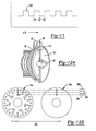
- Figure 12A is a view similar to that of Figure 10 but which illustrates the cover in more detail;
- Figure 12B is an exploded view of an alternately constructed optical sensor system that is configured to provide absolute position data
- Figure 13 is a partially sectioned perspective view of a portion of another sensor portion constructed in accordance with the teachings of the present disclosure
- Figure 14 is an exploded, partially sectioned perspective view of the sensor portion of Figure 13 ;
- Figure 15 is a partially sectioned perspective view of the sensor portion of Figure 13 , illustrating the sensor portion with the first annular light guide removed and the single window aligned to a tooth on the annular encoder;
- Figure 16 is a view similar to that of Figure 15 but illustrating the single window aligned to a space between adjacent teeth on the annular encoder wheel;
- Figure 17 is an exploded view of a portion of yet another sensor portion constructed in accordance with the teachings of the present disclosure.
- Figure 18 is a plot showing a relationship between the output of the optical sensor of the sensor portion of Figure 17 as a function of relative rotation between the sensor input member and the sensor output member;
- Figure 19 is similar to Figure 17 but illustrates first and second encoder wheels with relatively longer encoder windows that permit the sensor portion to measure torque in two rotary directions;
- Figure 20 is a plot showing a relationship between the output of the optical sensor of the sensor portion of Figure 19 as a function of relative rotation between the sensor input member and the sensor output member.
- Figure 21 is an exploded view of a portion of yet another sensor portion constructed in accordance with the teachings of the present disclosure.
- Figure 22 is a plot showing a relationship between the output of the optical sensor of the sensor portion of Figure 21 as a function of relative rotation between the sensor input member and the sensor output member.
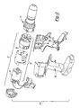
- an assembly constructed in accordance with the teachings of the present disclosure is generally indicated by reference numeral 10.
- the assembly 10 can include a tool portion 12 and a sensor portion 14.
- the assembly 10 is a driver having an integral torque sensor, but as those of ordinary skill will appreciate from this disclosure, the torque sensor (i.e., the sensor portion 14) can be fabricated as a stand-alone component and coupled in a suitable manner to a device that is configured to apply a torque (e.g., a power tool, a manual ratchet wrench).
- a torque e.g., a power tool, a manual ratchet wrench
- the tool portion 12 can be generally similar to the drill/driver that is described in U.S. Patent No. 6,431,289 entitled "Multi-Speed Power Tool Transmission".
- the tool portion 12 can include a housing 20 and a motor assembly 22 that can be housed in the housing 20.
- the motor assembly 22 can include a motor 24 and a transmission 26.
- the motor 24 can be an electric (e.g., battery powered and/or AC powered) motor that can provide a rotary input to the transmission 26.
- the transmission 26 can be operated in one or more speed reduction ratios that can be employed to multiply the torque and reduce the speed of the rotary power provided by the motor 24.
- the sensor portion 14 can include a sensor housing 40, a sensor input member 42, a sensor output member 44, a coupling member 46 and an optical sensor system 48.
- the sensor housing 40 can be non-rotatably coupled to the housing 20 ( Fig. 2 ) of the tool portion 12 ( Fig. 2 ) in an appropriate manner and can house the optical sensor system 48, as well as the sensor input member 42, the sensor output member 44 and the coupling member 46.
- the sensor input member 42 can include a first shank member 50, a piloting member 52 and a first body member 54 that can be disposed between the first shank member 50 and the piloting member 52.
- the first shank member 50 can be coupled for rotation with an output member 58 of the transmission 26.
- the piloting member 52 can be a shaft-like structure that can be received into an aperture 60 that can be formed in the sensor output member 44.
- the sensor output member 44 can include a second body member 62 and a second shank member 64.
- the second body member 62 can be generally cup-shaped in its construction to receive the coupling member 46 therein.
- the second shank member 64 can extend from the second body member 62 in a direction opposite the sensor input member 42.
- the coupling member 46 can be formed of a torsionally resilient material and can rotatably couple the sensor input member 42 to the sensor output member 44.
- the coupling member 46 includes a torsion spring 70 that is formed of a steel wire, but those of ordinary skill in the art will appreciate from this disclosure that the coupling member can be formed (in part or in whole) from any appropriate resilient material.
- the coupling member 46 is configured to deflect in a predetermined rotational direction when torque is transmitted between the sensor input member 42 and the sensor output member 44 in the predetermined rotational direction. As the coupling member 46 can have a predetermined torsional spring rate, the magnitude by which the coupling member 46 deflects is dependent upon the magnitude of the torque that is transmitted therethrough in the predetermined rotational direction.
- the torsion spring 70 includes a first end segment 72 that is non-rotatably coupled to the first body member 54 of the sensor input member 42, and a second end segment 74 that is non-rotatably coupled to the second body member 62 of the sensor output member 44.
- the first and second end segments 72 and 74 can be received into holes 76 and 78 that are formed into the first and second body members 54 and 62, respectively.
- the torsion spring 70 can be configured to expand radially when the tool portion 12 drives the sensor portion 14 in a rotational direction opposite the predetermined rotational direction to thereby lock the torsion spring 70 to the sensor output member 44.
- the torsion spring 70 can expand against the sensor housing 40 when the tool portion 12 drives the sensor portion 14 in a reverse or counterclockwise direction.
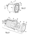
- the optical sensor system 48 can include a light source 90, a light guide 92, a first encoder wheel 94, a second encoder wheel 96, one or more optical sensors 98 and a controller 100.
- the light source 90 can be any appropriate light source, such as an incandescent lamp or a light emitting diode, and can generate light, such as visible light or infra red light.
- the light source 90 can be housed in the sensor housing 40 and directed toward the light guide 92.
- the light guide 92 can be an annular structure that can be formed of a transparent material.
- the light guide 92 can be configured to receive the light from the light source 90 and transmit the light toward the first encoder wheel 94.
- a reflector 102 can be formed into the light guide 92 to cause the light from the light source to reflect within the light guide 92 in a direction toward the first encoder wheel 94.
- Each of the first and second encoder wheels 94 and 96 can be formed of an opaque material.
- the first encoder wheel 94 can be non-rotatably coupled to the sensor output member 44
- the second encoder wheel 96 can be non-rotatably coupled to the sensor input member 42.
- a plurality of circumferentially spaced-apart windows 110 are formed in the first encoder wheel 94 at a distance (R) from the rotational center of the first encoder wheel 94, while a single window 112 is formed in the second encoder wheel 96 at the distance (R) from the rotational center of the second encoder wheel 96.
- the first encoder wheel 94 is positioned relative to the second encoder wheel 96 so that a first solid part 114a of the first encoder wheel 94 is positioned in-line with the single window 112 in the second encoder wheel 96 when no torque is transmitted between the sensor input member 42 and the sensor output member 44.
- the second encoder wheel 96 When increasing torque is applied in a predetermined rotational direction through the sensor portion 14, the second encoder wheel 96 will rotate relative to the first encoder wheel 94 due to the torsionally resilient nature of the coupling member 46. Accordingly, the single window 112 will rotate and sequentially align with the windows 110a, 110b, 110c, 110d and 110e. It will be appreciated that light can be transmitted through the second encoder wheel 96 when the single window 112 is aligned to one of the windows 110 in the first encoder wheel 94 and that light will not be transmitted through the second encoder wheel 96 when the single window 112 is aligned to a solid part 114 of the first encoder wheel 94 between adjacent ones of the windows 110.
- the optical sensor(s) 98 can be configured to detect light that is transmitted through the second encoder wheel 96.
- a single optical sensor 120 is employed and receives light from a second light guide 122.
- the single optical sensor 120 can be any type of optical sensor, such as a photo diode.
- the single optical sensor 120 can be housed by the sensor housing 40 and can be positioned at an appropriate position, such as spaced radially outwardly from the circumference of the second light guide 122.
- the second light guide 122 can be coupled to an appropriate structure, such as the sensor housing 40, and is configured to receive the light that is transmitted through the second encoder wheel 96 and to re-direct that light toward the single optical sensor 120.
- the second light guide 122 can employ a reflector 126 that can cause the light that is directed into the second light guide 122 to reflect in a desired direction, such as a radially outward direction.
- a reflector 126 that can cause the light that is directed into the second light guide 122 to reflect in a desired direction, such as a radially outward direction.
- the single optical sensor 120 will generate a first signal when light is not transmitted through the single window 112 of the second encoder wheel 96 and that the single optical sensor 120 will generate a second, different signal when light is transmitted through the single window 112.
- a plot showing the output of the single optical sensor 120 as a function of the magnitude of the rotation of the first encoder wheel 94 relative to the second encoder wheel 96 is illustrated in Figure 11 .
- the plot includes a plurality of pulses 140, each of which corresponding to a situation where the single window 112 ( Fig. 7 ) in the second encoder wheel 96 ( Fig. 7 ) is aligned to a corresponding one of the windows 110 ( Fig. 6 ) in the first encoder wheel 94 ( Fig. 6 ).
- an optional cover 150 can be coupled to the sensor housing 40 on a side of the second light guide 122 opposite the second encoder wheel 96.
- the controller 100 can be coupled to the single optical sensor 120 and can receive the signals generated by the single optical sensor 120.
- the controller 100 can be configured in an appropriate manner to interpret the signals received from the single optical sensor 120 to thereby gauge the magnitude of the torque that is being transmitted through the sensor portion 14.
- the controller 100 is configured to count the number (n) of pulses 140 ( Fig. 11 ) that are generated by the single optical sensor 120 and to employ the number (n) of pulses 140 ( Fig. 11 ) in the calculation of the magnitude of the transmitted torque. It will be appreciated that each pulse 140 ( Fig.
- the controller 100 can be coupled to a device 160 that can provide information (e.g., audible, visual, audible and visual) to the user of the tool portion 12.
- information e.g., audible, visual, audible and visual
- the device 160 can include a display 162 that can provide a readout with a numeric value of the torque that is transmitted through the sensor portion 14.
- the controller 100 may be programmed or programmable to permit the user to select the torque at which an appropriate action can be taken. Such actions include the generation of an audible signal, the generation of a control signal that is employed to halt the operation of the motor 24 that drives the tool portion 12 ( Fig. 1 ), the operation of the motor 24 in a second, slower speed, and/or the operation of the motor 24 such that it drives the sensor output member 44 (via the transmission 26 ( Fig. 2 ), the sensor input member 42 and the coupling member 46) through a predetermined angle of rotation, which may or may not be greater than 360°.
- the optical sensor system 48 in the particular example provided is configured to provide "incremental" torque data. More specifically, the optical sensor system 48 is configured to count pulses 140 ( Fig. 11 ) and assumes that the pulses 140 ( Fig. 11 ) are being generated via motion in a single predetermined rotational direction. As will be appreciated, if the torque applied to a work element first increases and then decreases so that pulses 140 ( Fig. 11 ) will be generated both as torque applied to the sensor output member 44 increases and as the torque applied to the sensor output member 44 diminishes, the optical sensor system 48 will not be able to differentiate between the pulses 140 ( Fig. 11 ) that were generated in the two rotational directions.
- optical sensor system 48 could be configured in the alternative as an absolute encoder rather than as an incremental encoder, which is described above as shown in Figure 12B , through the use of two or more optical sensors (e.g., optical sensors 98a, 98b, 98c) and first and second encoder wheels 94a and 96a that facilitate the transmission of a multi-bit set of data that uniquely identifies the relative position of the first and second encoder wheels 94a and 96a at each angular position.
- optical sensors 98a, 98b, 98c optical sensors 98a, 98b, 98c
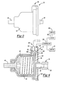
- FIG. 13 and 14 another sensor portion 14b is illustrated to be generally similar to the sensor portion 14 described above, except that the optical sensor system 48b has been aligned to an axis that is generally parallel to the rotational axis of the sensor input and output members 42b and 44b.
- a first annular light guide 92b is received into the sensor housing 40b and is configured to receive light from the light source 90b and to direct (e.g., reflect) the light from the light source 90b in a radially inward direction toward the second body member 62b of the sensor output member 44b.
- a single window 200 can be formed through the second body member 62b, which permits light to be transmitted toward an opaque annular encoder 202 that is fixed for rotation with the sensor input member 42b.
- the opaque annular encoder 202 can include a backing portion 204 and a plurality of circumferentially spaced apart teeth 206 that extend rearwardly from the backing portion 204.
- a second annular light guide 208 can be disposed radially inwardly of the opaque annular encoder 202 and can be non-rotatably coupled to the sensor housing 40b. It will be appreciated that light from the light source 90ba is transmitted into the first annular light guide 92b and directed through the single window 200 in the sensor output member 44b toward the opaque annular encoder 202.
- the second annular light guide 208 can include a reflector 220 that can direct light toward a single optical sensor 120b.
- FIG. 17 A portion of another sensor portion 14c constructed in accordance with the teachings of the present disclosure is illustrated in Figure 17 . It will be appreciated that while Figure 17 illustrates only the first and second encoder wheels 94c and 96c, respectively, these encoder wheels could be incorporated into the sensor portion 14 of Figure 3 . As such, the illustration and description of the remainder of the sensor portion 14c has not been (and need not be) included herein.
- the first encoder wheel 94c which can be formed of an opaque material, can include a window 500c that extends circumferentially about a portion of the first encoder wheel 94c.
- the second encoder wheel 96c which can be formed of an opaque material, includes a window 502c that extends about a portion of the second encoder wheel 96c.
- the window 502c can be positioned so as to overlap a space 504c on the first encoder wheel 94c so that light from a light source 90c is not transmitted through the second encoder wheel 96c and received by an optical sensor 98c.
- the window 502c can be increasingly aligned to the window 500c when the torque transmitted through the sensor portion 14c (in the predetermined direction) meets and then exceeds the predetermined threshold.
- the window 502c will overlap the window 500c by a relatively small amount when the torque transmitted through the sensor portion 14c (in the predetermined direction) equals the predetermined threshold, and that the amount of the overlap will increase as the amount of torque that is transmitted through the sensor portion 14c (in the predetermined direction) increases. It will also be appreciated from this disclosure that that as a consequence of the increasing overlapping of the window 502c with the window 500c, the amount of light transmitted through the second encoder wheel 96c will increase as the amount of torque that is transmitted through the sensor portion 14c (in the predetermined direction) increases beyond the predetermined threshold.
- the optical sensor 98c can be any type of sensor that can detect the relative magnitude or intensity of the light that is transmitted through the second encoder wheel 96c and generate an output responsively.
- An example of one suitable output of the optical sensor 98c is illustrated in the plot of Figure 18 .
- FIG. 19 A portion of another sensor portion 14d constructed in accordance with the teachings of the present disclosure is illustrated in Figure 19 . It will be appreciated that while Figure 19 illustrates only the first and second encoder wheels 94d and 96d, respectively, these encoder wheels could be incorporated into the sensor portion 14 of Figure 3 . As such, the illustration and description of the remainder of the sensor portion 14d has not been (and need not be) included herein.
- the first encoder wheel 94d which can be formed of an opaque material, can include a window 500d that extends circumferentially about a portion of the first encoder wheel 94d.
- the second encoder wheel 96d which can be formed of an opaque material, includes a window 502d that extends about a portion of the second encoder wheel 96d.
- the window 502d can be positioned so as to overlap a the window 500d on the first encoder wheel 94d so that a portion of the light from a light source 90d is transmitted through the second encoder wheel 96d and received by an optical sensor 98d.
- the window 502d can be increasingly aligned to the window 500d when the torque transmitted through the sensor portion 14d in the predetermined direction and can be decreasingly aligned to the window 500d when torque transmitted through the sensor portion 14d increases in a direction opposite the predetermined direction.
- the window 502d will overlap the window 500d by a first amount when no torque is transmitted the sensor portion 14d, that the amount of the overlap will increase as the amount of increasing torque is transmitted through the sensor portion 14d in the predetermined direction, and that the amount of the overlap will decrease as the amount of torque that is transmitted through the sensor portion 14d in the direction opposite the predetermined direction increases.
- the optical sensor 98d can be any type of sensor that can detect the relative magnitude or intensity of the light that is transmitted through the second encoder wheel 96d and generate an output responsively. An example of one suitable output of the optical sensor 98d is illustrated in the plot of Figure 20 .
- windows 500c and 502c of Figure 17 and the windows 500d and 502d of Figure 19 have been illustrated as a pair of slots having concentric inner and outer edges, it will be appreciated that the windows 500c, 502c, 500d and 502d could be formed somewhat differently.
- the windows 500c, 502c, 500d and 502d could be formed such that the amount of overlap increases and/or decreases in a non-linear manner.
- An example illustrating the construction of a first encoder wheel 94e and a second encoder wheel 96e with such windows is illustrated in Figure 21 .
- the first and second encoders 94e and 96e are initially arranged such that when the sensor portion 14e is not transmitting torque (in the predetermined direction) in excess of a predetermined threshold, the window 502e can be positioned so as to overlap a space 504e on the first encoder wheel 94c so that light from a light source 90e is not transmitted through the second encoder wheel 96e and received by an optical sensor 98e.
- the window 502e can be increasingly aligned to the window 500e when the torque transmitted through the sensor portion 14e (in the predetermined direction) meets and then exceeds the predetermined threshold.
- the window 502e will overlap the window 500e by a relatively small amount when the torque transmitted through the sensor portion 14e (in the predetermined direction) equals the predetermined threshold, and that the amount of the overlap will increase as the amount of torque that is transmitted through the sensor portion 14e (in the predetermined direction) increases.
- the amount of overlap between the windows 500e and 502e can increase in a non-linear manner as shown in Figure 22 .
Landscapes
- Engineering & Computer Science (AREA)
- Mechanical Engineering (AREA)
- Physics & Mathematics (AREA)
- General Physics & Mathematics (AREA)
- Optical Transform (AREA)
- Portable Power Tools In General (AREA)
- Force Measurement Appropriate To Specific Purposes (AREA)
- Details Of Spanners, Wrenches, And Screw Drivers And Accessories (AREA)
Claims (7)
- Capteur de couple (14, 14b, 14c, 14d, 14e) comprenant:un logement de capteur (40, 40b) ;un organe d'entrée de capteur (42, 42b) au moins partiellement reçu dans le logement de capteur ;un organe de sortie de capteur (44, 44b) au moins partiellement reçu dans le logement de capteur ;un organe de couplage résilient en torsion (46) qui couple l'organe d'entrée de capteur à l'organe de sortie de capteur ; etun système de capteur optique (48, 48b) qui inclut une source de lumière (90, 90b, 90c, 90d, 90e), au moins un encodeur et au moins un capteur optique (98, 98a, 98b, 98c, 98d, 98e), le au moins un encodeur transmettant périodiquement la lumière entre la source de lumière et le au moins un capteur optique en se basant sur une quantité de rotation relative entre l'organe d'entrée de capteur et l'organe de sortie de capteur ;caractérisé en ce que :le au moins un encodeur inclut une bague annulaire (202) avec une pluralité de dents circonférentiellement espacées (206) et une ouverture (200) qui est formée à travers l'organe de sortie de capteur ; et en ce queun premier guide de lumière annulaire (92, 92b) est disposé autour de l'organe de sortie de capteur et un second guide de lumière annulaire (122, 208) est disposé vers l'intérieur de la bague annulaire.
- Capteur de couple selon la revendication 1, dans lequel le au moins un capteur optique (98) est un capteur optique unique (120, 120b).
- Capteur de couple selon la revendication 1, dans lequel le au moins un encodeur inclut une première roue d'encodeur (94, 94a, 94b, 94c, 94d, 94e) qui est couplée pour rotation avec l'organe d'entrée de capteur (42).
- Capteur de couple selon la revendication 3, dans lequel le au moins un encodeur inclut une seconde roue d'encodeur (96, 96a, 96b, 96c, 96d, 96e) qui est couplée pour rotation avec l'organe de sortie de capteur (44).
- Capteur de couple selon la revendication 4, dans lequel les première et seconde roues d'encodeur sont espacées l'une de l'autre le long d'un axe de rotation de l'organe d'entrée de capteur (42).
- Capteur de couple selon la revendication 1, dans lequel l'organe de couplage (46) inclut un ressort de torsion (70) qui est formé de fil.
- Capteur de couple selon la revendication 1, dans lequel le système de capteur optique (48) est un encodeur incrémental.
Priority Applications (1)
| Application Number | Priority Date | Filing Date | Title |
|---|---|---|---|
| EP11177219.0A EP2397259A3 (fr) | 2006-09-12 | 2007-09-12 | Capteur de couple optique |
Applications Claiming Priority (2)
| Application Number | Priority Date | Filing Date | Title |
|---|---|---|---|
| US82533906P | 2006-09-12 | 2006-09-12 | |
| PCT/US2007/019794 WO2008033386A2 (fr) | 2006-09-12 | 2007-09-12 | Capteur de couple optique |
Related Child Applications (2)
| Application Number | Title | Priority Date | Filing Date |
|---|---|---|---|
| EP11177219.0A Division EP2397259A3 (fr) | 2006-09-12 | 2007-09-12 | Capteur de couple optique |
| EP11177219.0 Division-Into | 2011-08-11 |
Publications (3)
| Publication Number | Publication Date |
|---|---|
| EP2076748A2 EP2076748A2 (fr) | 2009-07-08 |
| EP2076748A4 EP2076748A4 (fr) | 2010-10-27 |
| EP2076748B1 true EP2076748B1 (fr) | 2013-08-28 |
Family
ID=39184313
Family Applications (3)
| Application Number | Title | Priority Date | Filing Date |
|---|---|---|---|
| EP11177219.0A Withdrawn EP2397259A3 (fr) | 2006-09-12 | 2007-09-12 | Capteur de couple optique |
| EP07838072.2A Not-in-force EP2076748B1 (fr) | 2006-09-12 | 2007-09-12 | Capteur de couple optique |
| EP07811753.8A Not-in-force EP2073953B1 (fr) | 2006-09-12 | 2007-09-12 | Organe d'entraînement avec indicateur de valeur de couple externe intégré à un verrouillage de broche et procédé apparenté |
Family Applications Before (1)
| Application Number | Title | Priority Date | Filing Date |
|---|---|---|---|
| EP11177219.0A Withdrawn EP2397259A3 (fr) | 2006-09-12 | 2007-09-12 | Capteur de couple optique |
Family Applications After (1)
| Application Number | Title | Priority Date | Filing Date |
|---|---|---|---|
| EP07811753.8A Not-in-force EP2073953B1 (fr) | 2006-09-12 | 2007-09-12 | Organe d'entraînement avec indicateur de valeur de couple externe intégré à un verrouillage de broche et procédé apparenté |
Country Status (4)
| Country | Link |
|---|---|
| US (2) | US7578357B2 (fr) |
| EP (3) | EP2397259A3 (fr) |
| CN (1) | CN201419340Y (fr) |
| WO (1) | WO2008033386A2 (fr) |
Families Citing this family (51)
| Publication number | Priority date | Publication date | Assignee | Title |
|---|---|---|---|---|
| JP4754395B2 (ja) * | 2006-04-20 | 2011-08-24 | 株式会社マキタ | ねじ締め機 |
| US7578357B2 (en) * | 2006-09-12 | 2009-08-25 | Black & Decker Inc. | Driver with external torque value indicator integrated with spindle lock and related method |
| US8732896B2 (en) | 2006-10-17 | 2014-05-27 | Mtd Products Inc | Hybrid electric cleaning device |
| WO2008048618A2 (fr) | 2006-10-17 | 2008-04-24 | Desa Ip. Llc | Dispositif électrique hybride |
| US8076873B1 (en) * | 2007-06-01 | 2011-12-13 | Mtd Products Inc | Hybrid outdoor power equipment |
| US8269612B2 (en) | 2008-07-10 | 2012-09-18 | Black & Decker Inc. | Communication protocol for remotely controlled laser devices |
| US20100096152A1 (en) * | 2008-10-16 | 2010-04-22 | Top Gearbox Industry Co., Ltd. | Lever type output shaft locking device |
| US9016398B2 (en) * | 2008-12-04 | 2015-04-28 | Ingersoll-Rand Company | Disc-shaped torque transducer |
| DE102009027442A1 (de) * | 2009-07-03 | 2011-01-05 | Robert Bosch Gmbh | Handwerkzeugmaschine |
| US8205510B2 (en) * | 2009-10-27 | 2012-06-26 | Diluigi And Associates, Llc | Hand brake torque input coupler and indicator |
| WO2011109930A1 (fr) * | 2010-03-08 | 2011-09-15 | Techtronic Power Tools Technology Limited | Outil électrique comprenant un dispositif de blocage de broche |
| US8584770B2 (en) | 2010-03-23 | 2013-11-19 | Black & Decker Inc. | Spindle bearing arrangement for a power tool |
| US8529567B2 (en) | 2010-06-03 | 2013-09-10 | Biomet Microfixation, Llc | Surgical device with smart bit recognition collet assembly to set a desired application mode |
| US20110303432A1 (en) * | 2010-06-14 | 2011-12-15 | Stauffer Joseph G | Power tool transmission |
| US8393231B2 (en) * | 2010-11-15 | 2013-03-12 | Legend Lifestyle Products Corp. | Multifunctional torque tool detection device |
| EP2707177B1 (fr) * | 2011-05-13 | 2019-01-09 | ABAS Inc. | Outil portatif à moteur pré-réglable |
| CN102814792B (zh) * | 2011-06-09 | 2014-12-17 | 苏州宝时得电动工具有限公司 | 动力工具及应用于该动力工具的工作头和转接器 |
| US8801569B2 (en) | 2011-12-14 | 2014-08-12 | Massachusetts Institute Of Technology | Methods and apparatus for flexure-based torque sensor in a bicycle |
| US8704904B2 (en) | 2011-12-23 | 2014-04-22 | H4 Engineering, Inc. | Portable system for high quality video recording |
| US9908182B2 (en) | 2012-01-30 | 2018-03-06 | Black & Decker Inc. | Remote programming of a power tool |
| US8836508B2 (en) | 2012-02-03 | 2014-09-16 | H4 Engineering, Inc. | Apparatus and method for securing a portable electronic device |
| JP6250568B2 (ja) | 2012-03-01 | 2017-12-20 | エイチ4 エンジニアリング, インコーポレイテッドH4 Engineering, Inc. | 自動ビデオ記録用の装置及び方法 |
| US9723192B1 (en) | 2012-03-02 | 2017-08-01 | H4 Engineering, Inc. | Application dependent video recording device architecture |
| CA2866131A1 (fr) | 2012-03-02 | 2013-06-09 | H4 Engineering, Inc. | Dispositif d'enregistrement video automatique multifonction |
| JP5895159B2 (ja) * | 2012-03-13 | 2016-03-30 | パナソニックIpマネジメント株式会社 | 動力工具 |
| US9193055B2 (en) | 2012-04-13 | 2015-11-24 | Black & Decker Inc. | Electronic clutch for power tool |
| US8919456B2 (en) | 2012-06-08 | 2014-12-30 | Black & Decker Inc. | Fastener setting algorithm for drill driver |
| US20130327552A1 (en) | 2012-06-08 | 2013-12-12 | Black & Decker Inc. | Power tool having multiple operating modes |
| US9007476B2 (en) | 2012-07-06 | 2015-04-14 | H4 Engineering, Inc. | Remotely controlled automatic camera tracking system |
| EP2720018A1 (fr) | 2012-10-15 | 2014-04-16 | Continental Automotive GmbH | Mesure de couple de torsion pour arbres rotatifs |
| CN104070490B (zh) * | 2013-03-29 | 2016-11-23 | 南京德朔实业有限公司 | 电动工具 |
| US9395257B2 (en) * | 2013-05-10 | 2016-07-19 | Snap-On Incorporated | Electronic torque tool with integrated real-time clock |
| DE102013209173A1 (de) * | 2013-05-17 | 2014-11-20 | Robert Bosch Gmbh | Handwerkzeugmaschine mit einer Spindellockvorrichtung |
| EP3021767B1 (fr) | 2013-07-19 | 2018-12-12 | Pro-Dex Inc. | Tournevis de limitation de couple |
| DE102014226325A1 (de) * | 2014-12-17 | 2016-06-23 | Sirona Dental Systems Gmbh | Zahnärztliches Instrument mit einem Getriebe zum Antrieb eines Werkzeugs |
| DE102014019547B3 (de) * | 2014-12-23 | 2016-05-12 | Samson Ag | Drehmoment- und Winkelsensor und Stellantrieb |
| WO2016196899A1 (fr) | 2015-06-05 | 2016-12-08 | Ingersoll-Rand Company | Boîtiers d'outil électrique |
| WO2016196984A1 (fr) * | 2015-06-05 | 2016-12-08 | Ingersoll-Rand Company | Machines portatives à moteur à modes de fonctionnement sélectionnables par l'utilisateur |
| WO2016196979A1 (fr) | 2015-06-05 | 2016-12-08 | Ingersoll-Rand Company | Outils de percussion avec fonctionnalités d'alignement de couronne dentée |
| US10615670B2 (en) | 2015-06-05 | 2020-04-07 | Ingersoll-Rand Industrial U.S., Inc. | Power tool user interfaces |
| CN114404015B (zh) | 2016-06-07 | 2024-06-21 | 普罗德克斯有限公司 | 扭矩限制装置 |
| US11453105B2 (en) | 2016-09-13 | 2022-09-27 | Milwaukee Electric Tool Corporation | Powered ratcheting torque wrench |
| US10625405B2 (en) | 2016-09-13 | 2020-04-21 | Milwaukee Electric Tool Corporation | Powered ratcheting torque wrench |
| GB2569764B (en) * | 2016-11-10 | 2022-01-12 | Nitto Kohki Co | Electric motor-driven tool, and control device and control circuit therefor |
| CA3105137A1 (fr) | 2018-08-20 | 2020-02-27 | Pro-Dex, Inc. | Dispositifs, systemes et procedes de limitation de couple |
| GB201904786D0 (en) | 2019-04-04 | 2019-05-22 | Norbar Torque Tools | Torque application tool |
| SE543291C2 (en) * | 2019-07-24 | 2020-11-17 | Atlas Copco Ind Technique Ab | Power tool attachment part with a torque sensor measuring strain |
| WO2021167880A1 (fr) | 2020-02-17 | 2021-08-26 | Milwaukee Electric Tool Corporation | Verrouillage de broche électronique pour un outil électrique |
| US11691259B2 (en) * | 2020-05-18 | 2023-07-04 | Techtronic Cordless Gp | Rotary tool |
| JP7628240B2 (ja) | 2020-10-15 | 2025-02-10 | 多摩川精機株式会社 | トルクセンサ |
| CN113059216B (zh) * | 2021-04-02 | 2023-05-09 | 浙江时中电器有限公司 | 一种防屑环保型电钻 |
Family Cites Families (73)
| Publication number | Priority date | Publication date | Assignee | Title |
|---|---|---|---|---|
| US3783682A (en) * | 1971-12-16 | 1974-01-08 | Bell Telephone Labor Inc | Torque testing screwdriver with automatic torque indicating means |
| SU386289A1 (ru) * | 1972-02-01 | 1973-06-14 | Устройство для определения крутящего момента валов сельскохозяйственных агрегатов | |
| US4019363A (en) * | 1973-10-09 | 1977-04-26 | Masoneilan International, Inc. | Calibration apparatus and method |
| US4249435A (en) * | 1979-07-30 | 1981-02-10 | Smith William J | Workpiece turning hand tool with torque control |
| US4540318A (en) * | 1982-07-29 | 1985-09-10 | Robert Bosch, Gmbh | Rotary electrical tool with speed control, especially drill |
| US4471280A (en) * | 1983-05-06 | 1984-09-11 | The Bendix Corporation | Anti-log power amplifier for reversible D.C. motor in automotive steering controls |
| GB2148493A (en) | 1983-09-12 | 1985-05-30 | Crane Electronics | Torque transducing attachments for air-driven impact tools |
| US4558601A (en) * | 1984-01-06 | 1985-12-17 | J. S. Technology, Inc. | Digital indicating torque wrench |
| ES8605898A1 (es) * | 1985-03-14 | 1986-03-16 | Bendiberica Sa | Perfeccionamientos en dispositivos captadores de par para mecanismo de accionamiento, especialmente de timoneria o ruedas orientables de un vehiculo |
| JPS62157523A (ja) * | 1985-12-28 | 1987-07-13 | Aisin Warner Ltd | 光式ロ−タリエンコ−ダ |
| US4845998A (en) * | 1988-02-01 | 1989-07-11 | Kent-Moore Corporation | Apparatus for precision tensioning of threaded fasteners |
| US5025903A (en) * | 1990-01-09 | 1991-06-25 | Black & Decker Inc. | Dual mode rotary power tool with adjustable output torque |
| US5686672A (en) * | 1990-12-10 | 1997-11-11 | Klauber; Robert D. | Stress and load variation detector |
| DE4039794A1 (de) * | 1990-12-13 | 1992-06-17 | Forst Saltus Werk | Drehmomentschluessel |
| DE59200150D1 (de) * | 1991-02-19 | 1994-06-09 | Horst Glonner | Auswertungseinrichtung für eine auf einer drehbaren welle erfasste messgrösse. |
| US5335557A (en) * | 1991-11-26 | 1994-08-09 | Taizo Yasutake | Touch sensitive input control device |
| US6597347B1 (en) * | 1991-11-26 | 2003-07-22 | Itu Research Inc. | Methods and apparatus for providing touch-sensitive input in multiple degrees of freedom |
| GB9202868D0 (en) * | 1992-02-12 | 1992-03-25 | Lucas Ind Plc | Optical torque sensors and steering systems for vehicles incorporating them |
| US5490430A (en) * | 1992-05-14 | 1996-02-13 | Anderson; Philip M. | Optical torque sensor utilizing change in reflectance grating line spacing |
| US5389780A (en) * | 1992-05-14 | 1995-02-14 | Anderson; Philip M. | Optical torque sensor utilizing single polarizing area filters and mechanical amplifier |
| JP3098358B2 (ja) * | 1992-11-27 | 2000-10-16 | 三菱電機株式会社 | 位置検出素子、その位置検出素子を用いた位置検出方法、および光学式ロータリーエンコーダ |
| DE4307131C2 (de) * | 1993-03-06 | 1995-11-16 | Albert Kipfelsberger | Kraftschrauber mit elektronischer Drehmomentbegrenzung |
| JPH06293265A (ja) * | 1993-04-07 | 1994-10-21 | Rhythm Corp | 電動パワーステアリング装置 |
| US5426986A (en) * | 1993-07-15 | 1995-06-27 | Northern Research & Engineering Corporation | Absorption dynamometer torque measuring device and calibration method |
| GB9316851D0 (en) * | 1993-08-13 | 1993-09-29 | Lucas Ind Plc | Enhanced position signals in optical torque sensors |
| GB9316841D0 (en) * | 1993-08-13 | 1993-09-29 | Lucas Ind Plc | Optical torque sensor incorporating sensor failure diagnostics |
| GB9316842D0 (en) * | 1993-08-13 | 1993-09-29 | Lucas Ind Plc | Improved optical torque sensor |
| US5535867A (en) * | 1993-11-01 | 1996-07-16 | Coccaro; Albert V. | Torque regulating coupling |
| GB9400511D0 (en) * | 1994-01-12 | 1994-03-09 | Lucas Ind Plc | Optical torque sensors |
| US5451127A (en) * | 1994-04-12 | 1995-09-19 | Chung; Lee-Hsin-Chih | Dual-function electrical hand drill |
| DE69520511T2 (de) * | 1994-08-25 | 2001-08-23 | Trw Lucas Varity Electric Steering Ltd., Solihull | Capteur de deplacement et capteur de couple |
| DE19708058A1 (de) * | 1997-02-28 | 1998-09-03 | Bock Orthopaed Ind | Muskelbetriebenes Radfahrzeug |
| US5788021A (en) * | 1997-06-05 | 1998-08-04 | Tsai; Feng Chun | Automatic outputshaft locking mechanism for electric tools |
| FR2774470B1 (fr) * | 1998-02-04 | 2000-03-03 | Roulements Soc Nouvelle | Capteur de couple et colonne de direction pourvue d'un tel capteur |
| JP2000002603A (ja) * | 1998-06-17 | 2000-01-07 | Koyo Seiko Co Ltd | トルクセンサ |
| US5984022A (en) * | 1998-07-09 | 1999-11-16 | Black & Decker Inc. | Automatic shaft lock |
| US6095020A (en) * | 1999-01-11 | 2000-08-01 | Beere Precision Medical Instruments, Inc. | Hand tool having a variable torque-limiting in-line drive |
| DE60036162T2 (de) * | 1999-02-11 | 2008-05-21 | Trw Automotive U.S. Llc, Livonia | Vorrichtung und verfahren zur steuerung einer elektrischen servolenkung |
| US6037735A (en) * | 1999-03-01 | 2000-03-14 | Eastman Kodak Company | Slow-speed servomechanism |
| US6536536B1 (en) * | 1999-04-29 | 2003-03-25 | Stephen F. Gass | Power tools |
| US6587211B1 (en) * | 1999-07-28 | 2003-07-01 | Creo Srl | Interferometric torque and power sensor |
| DE29914341U1 (de) * | 1999-08-16 | 1999-10-07 | Chung, Lee-Hsin-Chih, Chung-Li, Taoyuan | Drehknopf-Schalteinrichtung |
| US6729812B2 (en) * | 1999-12-06 | 2004-05-04 | Theodore G. Yaksich | Power driver having geared tool holder |
| US20020035876A1 (en) * | 2000-03-08 | 2002-03-28 | Donaldson Robert D. | Torque process control method and apparatus for fluid powered tools |
| CA2339430A1 (fr) * | 2000-03-10 | 2001-09-10 | Black & Decker Inc. | Marteau |
| US6268790B1 (en) * | 2000-03-24 | 2001-07-31 | Trw Inc. | Anti-theft method and apparatus |
| US6311787B1 (en) * | 2000-04-18 | 2001-11-06 | Black & Decker Inc. | Power driven rotary device |
| US6520274B1 (en) * | 2000-04-25 | 2003-02-18 | Visteon Global Technologies, Inc. | Modular electric steering gear assembly |
| US6805207B2 (en) * | 2001-01-23 | 2004-10-19 | Black & Decker Inc. | Housing with functional overmold |
| US6502648B2 (en) * | 2001-01-23 | 2003-01-07 | Black & Decker Inc. | 360 degree clutch collar |
| US6431289B1 (en) * | 2001-01-23 | 2002-08-13 | Black & Decker Inc. | Multi-speed power tool transmission |
| US7101300B2 (en) * | 2001-01-23 | 2006-09-05 | Black & Decker Inc. | Multispeed power tool transmission |
| US6676557B2 (en) * | 2001-01-23 | 2004-01-13 | Black & Decker Inc. | First stage clutch |
| US6460649B2 (en) * | 2001-02-16 | 2002-10-08 | Delphi Technologies, Inc. | Passive starting of a torque-ripple-free electric power steering system |
| JP2002254336A (ja) * | 2001-03-02 | 2002-09-10 | Hitachi Koki Co Ltd | 電動工具 |
| US6702090B2 (en) * | 2001-03-14 | 2004-03-09 | Milwaukee Electric Tool Corporation | Power tool and spindle lock system |
| US6547053B2 (en) * | 2001-03-30 | 2003-04-15 | Zf Meritor, Llc | Torsional vibration damper |
| US6817528B2 (en) * | 2001-07-17 | 2004-11-16 | Honeywell International Inc. | Reflective apparatus and method for optically sensing relative torque employing Moirè fringes |
| US7222862B2 (en) * | 2001-10-26 | 2007-05-29 | Black & Decker Inc. | Tool holder |
| US6915710B2 (en) * | 2001-11-06 | 2005-07-12 | Delphi Technology, Inc. | Method and apparatus for correcting attenuation in an optical torque sensor |
| US7063201B2 (en) * | 2001-11-27 | 2006-06-20 | Milwaukee Electric Tool Corporation | Power tool and spindle lock system |
| US6948381B1 (en) * | 2002-04-09 | 2005-09-27 | Rockwell Automation Technologies, Inc. | System and method for sensing torque on a rotating shaft |
| US7395871B2 (en) * | 2003-04-24 | 2008-07-08 | Black & Decker Inc. | Method for detecting a bit jam condition using a freely rotatable inertial mass |
| US6926095B2 (en) * | 2003-08-11 | 2005-08-09 | Power Network Industry Co., Ltd. | Power tool transmission device |
| JP4227028B2 (ja) * | 2004-01-09 | 2009-02-18 | 株式会社マキタ | ドライバドリル |
| JP4405900B2 (ja) * | 2004-03-10 | 2010-01-27 | 株式会社マキタ | インパクトドライバ |
| JP3899086B2 (ja) * | 2004-05-11 | 2007-03-28 | ミネベア株式会社 | 回転体トルク測定装置 |
| EP1792039A4 (fr) * | 2004-08-11 | 2010-09-15 | William Szieff | Outil dote d'indicateurs de mouvement et d'orientation |
| US7308948B2 (en) * | 2004-10-28 | 2007-12-18 | Makita Corporation | Electric power tool |
| US7377331B2 (en) * | 2005-04-06 | 2008-05-27 | Power Network Industry Co., Ltd. | Damping driving axle |
| US7588398B2 (en) * | 2005-04-19 | 2009-09-15 | Black & Decker Inc. | Tool chuck with power take off and dead spindle features |
| JP4754395B2 (ja) * | 2006-04-20 | 2011-08-24 | 株式会社マキタ | ねじ締め機 |
| US7578357B2 (en) * | 2006-09-12 | 2009-08-25 | Black & Decker Inc. | Driver with external torque value indicator integrated with spindle lock and related method |
-
2007
- 2007-09-11 US US11/853,600 patent/US7578357B2/en not_active Expired - Fee Related
- 2007-09-12 WO PCT/US2007/019794 patent/WO2008033386A2/fr not_active Ceased
- 2007-09-12 CN CN2007900000895U patent/CN201419340Y/zh not_active Expired - Fee Related
- 2007-09-12 EP EP11177219.0A patent/EP2397259A3/fr not_active Withdrawn
- 2007-09-12 EP EP07838072.2A patent/EP2076748B1/fr not_active Not-in-force
- 2007-09-12 EP EP07811753.8A patent/EP2073953B1/fr not_active Not-in-force
- 2007-09-12 US US11/854,110 patent/US7591195B2/en not_active Expired - Fee Related
Also Published As
| Publication number | Publication date |
|---|---|
| EP2073953A4 (fr) | 2017-10-04 |
| EP2397259A3 (fr) | 2017-12-27 |
| EP2073953B1 (fr) | 2019-06-26 |
| US7578357B2 (en) | 2009-08-25 |
| CN201419340Y (zh) | 2010-03-10 |
| US7591195B2 (en) | 2009-09-22 |
| US20080060487A1 (en) | 2008-03-13 |
| WO2008033386A3 (fr) | 2008-07-03 |
| EP2076748A4 (fr) | 2010-10-27 |
| EP2073953A2 (fr) | 2009-07-01 |
| EP2076748A2 (fr) | 2009-07-08 |
| US20080060451A1 (en) | 2008-03-13 |
| WO2008033386A2 (fr) | 2008-03-20 |
| EP2397259A2 (fr) | 2011-12-21 |
Similar Documents
| Publication | Publication Date | Title |
|---|---|---|
| EP2076748B1 (fr) | Capteur de couple optique | |
| US7757587B2 (en) | Bolt or nut tightening device | |
| US7395871B2 (en) | Method for detecting a bit jam condition using a freely rotatable inertial mass | |
| US9175745B2 (en) | Handheld power tool having a planetary gear | |
| EP2205401B1 (fr) | Outil électrique doté d'un embrayage à friction | |
| AU2380100A (en) | Torque indicator ratchet wrench for dentistry | |
| US20090194305A1 (en) | Power tool | |
| US10197146B2 (en) | Reducer module with real-time torque sensing | |
| CN104626069A (zh) | 手持式工具机 | |
| US7311027B1 (en) | Electric screwdriver | |
| EP2164680A1 (fr) | Unité de détection de couple pour outil électrique et outil électrique comprenant une telle unité de détection de couple | |
| WO2004048899A3 (fr) | Dispositif et procede de detection d'un angle de rotation | |
| US5901807A (en) | Electrical drive for a bicycle | |
| US6035746A (en) | Gear transmission cartridge | |
| EP1403173A3 (fr) | Dispositif pour détecter l'état de direction | |
| JP2003166887A (ja) | トルク検出装置 | |
| US20250229401A1 (en) | Power tool | |
| US9555534B2 (en) | Rotary screw driving tool without reactionary force in the handle | |
| KR102920175B1 (ko) | 펄스 유닛을 포함하는 동력 공구 | |
| WO2002062602A3 (fr) | Detection de couple pour systeme de direction | |
| EP1930123B1 (fr) | Tournevis électrique | |
| JP2009061541A (ja) | 過負荷検出機構及びそれを備えた産業用ロボット | |
| CN114144283A (zh) | 动力工具附接部件 | |
| ATE292277T1 (de) | Vorrichtung zum messen von drehmomenten und der drehrichtung in einer antriebsanordnung | |
| JP2002062202A (ja) | パワーステアリング用トルク検出装置 |
Legal Events
| Date | Code | Title | Description |
|---|---|---|---|
| PUAI | Public reference made under article 153(3) epc to a published international application that has entered the european phase |
Free format text: ORIGINAL CODE: 0009012 |
|
| 17P | Request for examination filed |
Effective date: 20090401 |
|
| AK | Designated contracting states |
Kind code of ref document: A2 Designated state(s): AT BE BG CH CY CZ DE DK EE ES FI FR GB GR HU IE IS IT LI LT LU LV MC MT NL PL PT RO SE SI SK TR |
|
| A4 | Supplementary search report drawn up and despatched |
Effective date: 20100923 |
|
| RIC1 | Information provided on ipc code assigned before grant |
Ipc: B25B 23/145 20060101ALI20100917BHEP Ipc: G01L 3/00 20060101AFI20090409BHEP |
|
| REG | Reference to a national code |
Ref country code: DE Ref legal event code: R079 Ref document number: 602007032571 Country of ref document: DE Free format text: PREVIOUS MAIN CLASS: G01L0003000000 Ipc: B25B0023147000 |
|
| GRAP | Despatch of communication of intention to grant a patent |
Free format text: ORIGINAL CODE: EPIDOSNIGR1 |
|
| RIC1 | Information provided on ipc code assigned before grant |
Ipc: B25B 23/147 20060101AFI20130318BHEP Ipc: B25B 23/145 20060101ALI20130318BHEP Ipc: G01L 3/12 20060101ALI20130318BHEP |
|
| INTG | Intention to grant announced |
Effective date: 20130410 |
|
| GRAS | Grant fee paid |
Free format text: ORIGINAL CODE: EPIDOSNIGR3 |
|
| GRAA | (expected) grant |
Free format text: ORIGINAL CODE: 0009210 |
|
| AK | Designated contracting states |
Kind code of ref document: B1 Designated state(s): AT BE BG CH CY CZ DE DK EE ES FI FR GB GR HU IE IS IT LI LT LU LV MC MT NL PL PT RO SE SI SK TR |
|
| REG | Reference to a national code |
Ref country code: GB Ref legal event code: FG4D |
|
| REG | Reference to a national code |
Ref country code: CH Ref legal event code: EP |
|
| REG | Reference to a national code |
Ref country code: AT Ref legal event code: REF Ref document number: 629019 Country of ref document: AT Kind code of ref document: T Effective date: 20130915 |
|
| REG | Reference to a national code |
Ref country code: IE Ref legal event code: FG4D |
|
| REG | Reference to a national code |
Ref country code: DE Ref legal event code: R096 Ref document number: 602007032571 Country of ref document: DE Effective date: 20131024 |
|
| REG | Reference to a national code |
Ref country code: AT Ref legal event code: MK05 Ref document number: 629019 Country of ref document: AT Kind code of ref document: T Effective date: 20130828 |
|
| REG | Reference to a national code |
Ref country code: LT Ref legal event code: MG4D |
|
| REG | Reference to a national code |
Ref country code: NL Ref legal event code: VDEP Effective date: 20130828 |
|
| PG25 | Lapsed in a contracting state [announced via postgrant information from national office to epo] |
Ref country code: PT Free format text: LAPSE BECAUSE OF FAILURE TO SUBMIT A TRANSLATION OF THE DESCRIPTION OR TO PAY THE FEE WITHIN THE PRESCRIBED TIME-LIMIT Effective date: 20131230 Ref country code: CY Free format text: LAPSE BECAUSE OF FAILURE TO SUBMIT A TRANSLATION OF THE DESCRIPTION OR TO PAY THE FEE WITHIN THE PRESCRIBED TIME-LIMIT Effective date: 20130731 Ref country code: AT Free format text: LAPSE BECAUSE OF FAILURE TO SUBMIT A TRANSLATION OF THE DESCRIPTION OR TO PAY THE FEE WITHIN THE PRESCRIBED TIME-LIMIT Effective date: 20130828 Ref country code: LT Free format text: LAPSE BECAUSE OF FAILURE TO SUBMIT A TRANSLATION OF THE DESCRIPTION OR TO PAY THE FEE WITHIN THE PRESCRIBED TIME-LIMIT Effective date: 20130828 Ref country code: SE Free format text: LAPSE BECAUSE OF FAILURE TO SUBMIT A TRANSLATION OF THE DESCRIPTION OR TO PAY THE FEE WITHIN THE PRESCRIBED TIME-LIMIT Effective date: 20130828 Ref country code: IS Free format text: LAPSE BECAUSE OF FAILURE TO SUBMIT A TRANSLATION OF THE DESCRIPTION OR TO PAY THE FEE WITHIN THE PRESCRIBED TIME-LIMIT Effective date: 20131228 |
|
| REG | Reference to a national code |
Ref country code: NL Ref legal event code: VDEP Effective date: 20130828 |
|
| PG25 | Lapsed in a contracting state [announced via postgrant information from national office to epo] |
Ref country code: GR Free format text: LAPSE BECAUSE OF FAILURE TO SUBMIT A TRANSLATION OF THE DESCRIPTION OR TO PAY THE FEE WITHIN THE PRESCRIBED TIME-LIMIT Effective date: 20131129 Ref country code: PL Free format text: LAPSE BECAUSE OF FAILURE TO SUBMIT A TRANSLATION OF THE DESCRIPTION OR TO PAY THE FEE WITHIN THE PRESCRIBED TIME-LIMIT Effective date: 20130828 Ref country code: BE Free format text: LAPSE BECAUSE OF FAILURE TO SUBMIT A TRANSLATION OF THE DESCRIPTION OR TO PAY THE FEE WITHIN THE PRESCRIBED TIME-LIMIT Effective date: 20130828 Ref country code: FI Free format text: LAPSE BECAUSE OF FAILURE TO SUBMIT A TRANSLATION OF THE DESCRIPTION OR TO PAY THE FEE WITHIN THE PRESCRIBED TIME-LIMIT Effective date: 20130828 Ref country code: SI Free format text: LAPSE BECAUSE OF FAILURE TO SUBMIT A TRANSLATION OF THE DESCRIPTION OR TO PAY THE FEE WITHIN THE PRESCRIBED TIME-LIMIT Effective date: 20130828 Ref country code: LV Free format text: LAPSE BECAUSE OF FAILURE TO SUBMIT A TRANSLATION OF THE DESCRIPTION OR TO PAY THE FEE WITHIN THE PRESCRIBED TIME-LIMIT Effective date: 20130828 |
|
| PG25 | Lapsed in a contracting state [announced via postgrant information from national office to epo] |
Ref country code: CY Free format text: LAPSE BECAUSE OF FAILURE TO SUBMIT A TRANSLATION OF THE DESCRIPTION OR TO PAY THE FEE WITHIN THE PRESCRIBED TIME-LIMIT Effective date: 20130828 |
|
| PG25 | Lapsed in a contracting state [announced via postgrant information from national office to epo] |
Ref country code: SK Free format text: LAPSE BECAUSE OF FAILURE TO SUBMIT A TRANSLATION OF THE DESCRIPTION OR TO PAY THE FEE WITHIN THE PRESCRIBED TIME-LIMIT Effective date: 20130828 Ref country code: DK Free format text: LAPSE BECAUSE OF FAILURE TO SUBMIT A TRANSLATION OF THE DESCRIPTION OR TO PAY THE FEE WITHIN THE PRESCRIBED TIME-LIMIT Effective date: 20130828 Ref country code: RO Free format text: LAPSE BECAUSE OF FAILURE TO SUBMIT A TRANSLATION OF THE DESCRIPTION OR TO PAY THE FEE WITHIN THE PRESCRIBED TIME-LIMIT Effective date: 20130828 Ref country code: NL Free format text: LAPSE BECAUSE OF FAILURE TO SUBMIT A TRANSLATION OF THE DESCRIPTION OR TO PAY THE FEE WITHIN THE PRESCRIBED TIME-LIMIT Effective date: 20130828 Ref country code: EE Free format text: LAPSE BECAUSE OF FAILURE TO SUBMIT A TRANSLATION OF THE DESCRIPTION OR TO PAY THE FEE WITHIN THE PRESCRIBED TIME-LIMIT Effective date: 20130828 Ref country code: CZ Free format text: LAPSE BECAUSE OF FAILURE TO SUBMIT A TRANSLATION OF THE DESCRIPTION OR TO PAY THE FEE WITHIN THE PRESCRIBED TIME-LIMIT Effective date: 20130828 |
|
| REG | Reference to a national code |
Ref country code: CH Ref legal event code: PL |
|
| PG25 | Lapsed in a contracting state [announced via postgrant information from national office to epo] |
Ref country code: MC Free format text: LAPSE BECAUSE OF FAILURE TO SUBMIT A TRANSLATION OF THE DESCRIPTION OR TO PAY THE FEE WITHIN THE PRESCRIBED TIME-LIMIT Effective date: 20130828 Ref country code: IT Free format text: LAPSE BECAUSE OF FAILURE TO SUBMIT A TRANSLATION OF THE DESCRIPTION OR TO PAY THE FEE WITHIN THE PRESCRIBED TIME-LIMIT Effective date: 20130828 Ref country code: ES Free format text: LAPSE BECAUSE OF FAILURE TO SUBMIT A TRANSLATION OF THE DESCRIPTION OR TO PAY THE FEE WITHIN THE PRESCRIBED TIME-LIMIT Effective date: 20130828 |
|
| REG | Reference to a national code |
Ref country code: DE Ref legal event code: R097 Ref document number: 602007032571 Country of ref document: DE |
|
| REG | Reference to a national code |
Ref country code: IE Ref legal event code: MM4A |
|
| PLBE | No opposition filed within time limit |
Free format text: ORIGINAL CODE: 0009261 |
|
| STAA | Information on the status of an ep patent application or granted ep patent |
Free format text: STATUS: NO OPPOSITION FILED WITHIN TIME LIMIT |
|
| PG25 | Lapsed in a contracting state [announced via postgrant information from national office to epo] |
Ref country code: IE Free format text: LAPSE BECAUSE OF NON-PAYMENT OF DUE FEES Effective date: 20130912 Ref country code: CH Free format text: LAPSE BECAUSE OF NON-PAYMENT OF DUE FEES Effective date: 20130930 Ref country code: LI Free format text: LAPSE BECAUSE OF NON-PAYMENT OF DUE FEES Effective date: 20130930 |
|
| 26N | No opposition filed |
Effective date: 20140530 |
|
| REG | Reference to a national code |
Ref country code: DE Ref legal event code: R097 Ref document number: 602007032571 Country of ref document: DE Effective date: 20140530 |
|
| PG25 | Lapsed in a contracting state [announced via postgrant information from national office to epo] |
Ref country code: TR Free format text: LAPSE BECAUSE OF FAILURE TO SUBMIT A TRANSLATION OF THE DESCRIPTION OR TO PAY THE FEE WITHIN THE PRESCRIBED TIME-LIMIT Effective date: 20130828 Ref country code: MT Free format text: LAPSE BECAUSE OF FAILURE TO SUBMIT A TRANSLATION OF THE DESCRIPTION OR TO PAY THE FEE WITHIN THE PRESCRIBED TIME-LIMIT Effective date: 20130828 |
|
| PG25 | Lapsed in a contracting state [announced via postgrant information from national office to epo] |
Ref country code: BG Free format text: LAPSE BECAUSE OF FAILURE TO SUBMIT A TRANSLATION OF THE DESCRIPTION OR TO PAY THE FEE WITHIN THE PRESCRIBED TIME-LIMIT Effective date: 20130828 Ref country code: HU Free format text: LAPSE BECAUSE OF FAILURE TO SUBMIT A TRANSLATION OF THE DESCRIPTION OR TO PAY THE FEE WITHIN THE PRESCRIBED TIME-LIMIT; INVALID AB INITIO Effective date: 20070912 Ref country code: LU Free format text: LAPSE BECAUSE OF NON-PAYMENT OF DUE FEES Effective date: 20130912 |
|
| REG | Reference to a national code |
Ref country code: FR Ref legal event code: PLFP Year of fee payment: 10 |
|
| REG | Reference to a national code |
Ref country code: FR Ref legal event code: PLFP Year of fee payment: 11 |
|
| REG | Reference to a national code |
Ref country code: FR Ref legal event code: PLFP Year of fee payment: 12 |
|
| PGFP | Annual fee paid to national office [announced via postgrant information from national office to epo] |
Ref country code: SE Payment date: 20180911 Year of fee payment: 17 |
|
| PGFP | Annual fee paid to national office [announced via postgrant information from national office to epo] |
Ref country code: GB Payment date: 20190912 Year of fee payment: 13 |
|
| PG25 | Lapsed in a contracting state [announced via postgrant information from national office to epo] |
Ref country code: FR Free format text: LAPSE BECAUSE OF NON-PAYMENT OF DUE FEES Effective date: 20190930 |
|
| PGFP | Annual fee paid to national office [announced via postgrant information from national office to epo] |
Ref country code: DE Payment date: 20200901 Year of fee payment: 14 |
|
| GBPC | Gb: european patent ceased through non-payment of renewal fee |
Effective date: 20200912 |
|
| PG25 | Lapsed in a contracting state [announced via postgrant information from national office to epo] |
Ref country code: GB Free format text: LAPSE BECAUSE OF NON-PAYMENT OF DUE FEES Effective date: 20200912 |
|
| REG | Reference to a national code |
Ref country code: DE Ref legal event code: R119 Ref document number: 602007032571 Country of ref document: DE |
|
| PG25 | Lapsed in a contracting state [announced via postgrant information from national office to epo] |
Ref country code: DE Free format text: LAPSE BECAUSE OF NON-PAYMENT OF DUE FEES Effective date: 20220401 |