EP2077068B1 - Vorrichtung zur Pflanzenkultivierung - Google Patents
Vorrichtung zur Pflanzenkultivierung Download PDFInfo
- Publication number
- EP2077068B1 EP2077068B1 EP08291251A EP08291251A EP2077068B1 EP 2077068 B1 EP2077068 B1 EP 2077068B1 EP 08291251 A EP08291251 A EP 08291251A EP 08291251 A EP08291251 A EP 08291251A EP 2077068 B1 EP2077068 B1 EP 2077068B1
- Authority
- EP
- European Patent Office
- Prior art keywords
- tray
- water
- reserve
- pump
- assembly according
- Prior art date
- Legal status (The legal status is an assumption and is not a legal conclusion. Google has not performed a legal analysis and makes no representation as to the accuracy of the status listed.)
- Not-in-force
Links
- XLYOFNOQVPJJNP-UHFFFAOYSA-N water Substances O XLYOFNOQVPJJNP-UHFFFAOYSA-N 0.000 claims abstract description 87
- 239000000758 substrate Substances 0.000 claims abstract description 34
- 230000008635 plant growth Effects 0.000 claims abstract 2
- 230000000007 visual effect Effects 0.000 claims description 2
- 239000011248 coating agent Substances 0.000 claims 1
- 238000000576 coating method Methods 0.000 claims 1
- 238000000034 method Methods 0.000 abstract description 5
- 230000005484 gravity Effects 0.000 abstract description 4
- 238000004519 manufacturing process Methods 0.000 abstract description 4
- 239000012530 fluid Substances 0.000 abstract description 2
- 238000005461 lubrication Methods 0.000 abstract 1
- 239000003643 water by type Substances 0.000 abstract 1
- 230000008901 benefit Effects 0.000 description 6
- 238000007664 blowing Methods 0.000 description 3
- 238000001175 rotational moulding Methods 0.000 description 3
- 230000035939 shock Effects 0.000 description 3
- 230000009471 action Effects 0.000 description 2
- 239000003651 drinking water Substances 0.000 description 2
- 235000020188 drinking water Nutrition 0.000 description 2
- 230000002262 irrigation Effects 0.000 description 2
- 238000003973 irrigation Methods 0.000 description 2
- 239000000463 material Substances 0.000 description 2
- 238000000465 moulding Methods 0.000 description 2
- 239000004033 plastic Substances 0.000 description 2
- 229920003023 plastic Polymers 0.000 description 2
- -1 polyethylene Polymers 0.000 description 2
- 235000019640 taste Nutrition 0.000 description 2
- 238000011282 treatment Methods 0.000 description 2
- 241000256113 Culicidae Species 0.000 description 1
- 239000004698 Polyethylene Substances 0.000 description 1
- 239000004743 Polypropylene Substances 0.000 description 1
- 241001080024 Telles Species 0.000 description 1
- 241000607479 Yersinia pestis Species 0.000 description 1
- 238000010521 absorption reaction Methods 0.000 description 1
- 239000011324 bead Substances 0.000 description 1
- 230000009286 beneficial effect Effects 0.000 description 1
- 230000033228 biological regulation Effects 0.000 description 1
- 230000009194 climbing Effects 0.000 description 1
- 239000003086 colorant Substances 0.000 description 1
- 238000005034 decoration Methods 0.000 description 1
- 238000001514 detection method Methods 0.000 description 1
- 238000009826 distribution Methods 0.000 description 1
- 238000005553 drilling Methods 0.000 description 1
- 230000008030 elimination Effects 0.000 description 1
- 238000003379 elimination reaction Methods 0.000 description 1
- 230000008029 eradication Effects 0.000 description 1
- 230000002349 favourable effect Effects 0.000 description 1
- 230000036541 health Effects 0.000 description 1
- 230000006872 improvement Effects 0.000 description 1
- 238000002347 injection Methods 0.000 description 1
- 239000007924 injection Substances 0.000 description 1
- 238000009434 installation Methods 0.000 description 1
- 238000009413 insulation Methods 0.000 description 1
- 238000002955 isolation Methods 0.000 description 1
- 231100001231 less toxic Toxicity 0.000 description 1
- 239000002184 metal Substances 0.000 description 1
- 239000000203 mixture Substances 0.000 description 1
- 238000003032 molecular docking Methods 0.000 description 1
- 235000015097 nutrients Nutrition 0.000 description 1
- 238000010422 painting Methods 0.000 description 1
- 238000005192 partition Methods 0.000 description 1
- 230000002093 peripheral effect Effects 0.000 description 1
- 229920000573 polyethylene Polymers 0.000 description 1
- 229920001155 polypropylene Polymers 0.000 description 1
- 230000008569 process Effects 0.000 description 1
- 230000002035 prolonged effect Effects 0.000 description 1
- 238000005086 pumping Methods 0.000 description 1
- 238000011084 recovery Methods 0.000 description 1
- 230000009467 reduction Effects 0.000 description 1
- 230000001629 suppression Effects 0.000 description 1
- 239000012815 thermoplastic material Substances 0.000 description 1
- 230000001960 triggered effect Effects 0.000 description 1
- 238000003466 welding Methods 0.000 description 1
- 239000002023 wood Substances 0.000 description 1
Images



Classifications
-
- A—HUMAN NECESSITIES
- A01—AGRICULTURE; FORESTRY; ANIMAL HUSBANDRY; HUNTING; TRAPPING; FISHING
- A01G—HORTICULTURE; CULTIVATION OF VEGETABLES, FLOWERS, RICE, FRUIT, VINES, HOPS OR SEAWEED; FORESTRY; WATERING
- A01G27/00—Self-acting watering devices, e.g. for flower-pots
- A01G27/005—Reservoirs connected to flower-pots through conduits
-
- A—HUMAN NECESSITIES
- A01—AGRICULTURE; FORESTRY; ANIMAL HUSBANDRY; HUNTING; TRAPPING; FISHING
- A01G—HORTICULTURE; CULTIVATION OF VEGETABLES, FLOWERS, RICE, FRUIT, VINES, HOPS OR SEAWEED; FORESTRY; WATERING
- A01G27/00—Self-acting watering devices, e.g. for flower-pots
- A01G27/02—Self-acting watering devices, e.g. for flower-pots having a water reservoir, the main part thereof being located wholly around or directly beside the growth substrate
Definitions
- the present invention relates to a device for growing plants, comprising a tray for a growth substrate of a plant and a water reserve.
- These devices are typically in the form of a tray for containing the culture substrate for the plant, and comprising a double bottom in which a reserve of water is formed.
- This double bottom is not waterproof but has openings allowing the water to rise by capillarity in the substrate to be absorbed by the roots of the plant.
- this type of reserve has a limited volume that corresponds to an autonomy of a few days, insufficient in case of prolonged absence of the owner of the plants (holidays).
- this principle has a disadvantage for the bottom roots which are constantly subjected to high humidity, and can cause their decay and death of a part of the plant.
- this principle by capillarity is also related to the quality of the substrate, which makes it therefore random.
- the most favorable watering mode for a harmonious growth of the plant is a permanent drip irrigation on the surface of the substrate, which allows a homogeneous distribution of the water through the thickness of the latter and absorption by the roots without exposing them to excessive moisture.
- the autonomous devices are very rudimentary: they are for example in the form of a bottle of water spilled on the tray with a device capillarity by gravity, or a water tank with capillaries to feed several bins.
- the bins proposed in the trade have a simple wall which has no function of insulating the roots of the plant vis-à-vis thermal shocks. Indeed plants outside are particularly exposed to frost in winter and burns in summer, particularly due to the action of infra-red on the walls of the tray, especially, as is common, if they are of dark color.
- a set for the cultivation of plants according to the preamble of claim 1 is disclosed in the document DE 9006 9884 .
- One of the aims of the invention is therefore to overcome all the disadvantages of the aforementioned devices by providing a device for growing plants with a water tank or nutrient mixture with greater autonomy.
- Another object of the invention is to allow a regular, permanent, simple and economical, watering the plant healthier.
- Another object of the invention is to provide root insulation with respect to thermal shocks; finally, a last object of the invention is to provide an aesthetic device.
- an assembly for growing plants comprising a tray for a growth substrate of a plant and a water supply according to claim 1.
- said additional reservoir is supplied with water from the reserve by a pump.
- the pump is immersed in the reserve.
- the assembly advantageously comprises a control means of the pump adapted to control the operation of the pump at specific times.
- the watering means preferably comprises a dripper, so that the plant is watered by a permanent drip.
- the assembly preferably comprises means for indicating the level of the water in the reserve.
- the inner wall is sealed, so that the tray containing the substrate is sealed against the water supply.
- the main tray comprises on its outer face at least one aspect skin, interchangeable, thus obtaining a global modular aesthetic assembly (the plant and its tray).
- the bottom of the main tray comprises on its outer face pads and the upper edge of the main tray comprises housings adapted to receive pads of a second tray similar to said tray.
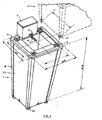
- the device comprises a tray 2 for the substrate, for example placed on a water reserve 3 whose interior volume is sufficient to meet the water requirements of the plant for a fixed period.
- the water supply 3 comprises a filling orifice provided with a stopper 34, and a drain orifice 37.
- a light indicator such as a light-emitting diode (LED) or a buzzer.
- One of the original features of the assembly according to the invention is that it comprises an additional water reservoir 4 situated above the upper surface 21 of the substrate 20.
- the additional reservoir 4 is for this purpose provided with at least one watering means 5 operating simply by gravity.
- the volume of the additional tank is for example between half a liter and two liters.
- the watering means 5 comprises a capillary tube 50 provided at its free end with a dripper 51.
- the dripper 51 may be bought commercially and the amount of water that passes is adjustable according to the needs of the plant.
- the outlet of the additional tank can be closed by means of a tap 52 (illustrated for example in FIG. figure 5 ).
- the tap is usually integrated into the dripper.
- watering means is not limited: indeed, as on the figure 4 several watering means can be provided, each of which makes it possible to water, in a differentiated manner, different portions of the tank.
- one of the watering means can be connected to a capillary which also feeds traditional pots arranged nearby.
- the additional reservoir 4 is in fluid relation with the water reserve 3.
- the pump can also be disposed outside the water reserve 3, (the pump is then self-priming, and equipped with a capillary which is immersed in the water reserve) and for example, in the form of a module comprising the additional reservoir, the pump and an electronic device for controlling the pump.
- the pump 31 is supplied with energy by any appropriate means 32.
- 1.5-volt batteries or rechargeable batteries may be arranged in a housing provided for this purpose in the water supply, or in a housing of the additional reservoir 4, and connected to the pump by means of a wire electrical 44 housed in a waterproof sheath.
- a solar collector can be arranged on the water reserve and the pump can then be powered by a battery system associated with solar energy.
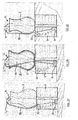
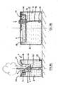
- FIGS. 2A to 2D illustrate different variants of arrangement of the water reserve 3 with respect to the tank 2 containing the plant and to the additional water tank 4.
- the tray 2 is placed on the water reserve 3.
- a pump 31 is immersed in the reserve 3 and supplies water to the tank 4 situated above the tank 2, by means of a capillary 35.
- the capillary 35 is external to the tank 2 and connects the pump to the additional tank.
- This embodiment is particularly suitable in the case where there is a plant installed in a tray that is desired to keep.
- the capillary 35 can pass inside the substrate of the tray 2, which makes its presence even more discreet.
- the reserve 3 can be buried in the ground, thus making the reserve 3 completely invisible.
- reserve 3 can also be installed on the ground, behind the tray 2.
- the device therefore gives the user complete freedom of arrangement according to the place where the plants are installed (interior, courtyard or garden), and his intention to keep or not the original tray of plants.
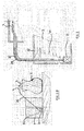
- the figure 3 illustrates in detail the principle of the filling device of the additional reservoir 4 (here partially illustrated).
- the pump 31 is immersed in the water reserve 3 (only part of which is shown).
- the capillary 35 which connects the pump 31 to the reservoir 4 is inserted into a sheath 36 of inside diameter greater than the outside diameter of the capillary 35.
- the gap between the capillary 35 and the sheath 36 constitutes an overflow device by means of which excess water in the tank 4 is discharged towards the reserve 3 (as indicated by the arrows).
- the orifice of the sheath 36 should always be at least a few millimeters lower than the capillary inlet of the fountain.
- a reliable fastening means at least 5 mm above the end of the sheath 36 of overflow
- the plant is watered by a continuous drip from the water of the additional tank 4. It thus benefits from the most beneficial watering mode for its growth, thus getting closer to from the principle of nature, by gravity, the rain.
- the device is provided with a switch 17 (not shown on the figure 3 ), which makes it possible to put in operation the control device of the pump or its stop. It is also possible to turn off the ignition by unplugging the batteries.
- the additional water tank 4 is periodically filled by means of the pump 31, which is equipped with an electronic module 40 which is particularly simple and inexpensive, controlling its operation at predetermined regular intervals, for example every 6 hours, or triggered by a water level sensor of the fountain, itself connected to the electronic module 40 (not shown in the figures).
- an electronic module 40 which is particularly simple and inexpensive, controlling its operation at predetermined regular intervals, for example every 6 hours, or triggered by a water level sensor of the fountain, itself connected to the electronic module 40 (not shown in the figures).
- the invention makes it possible to provide a reserve of water of a large volume, but not disposed, as in the prior art, above the tray for the substrate, which is unsightly, but below, or next, which allows to make it more discreet (likened to a support for the tank of the plant or possibly hidden behind it).
- the additional water tank located above the surface of the substrate can then be of a low volume, which makes it less visible and easier to integrate with the substrate tray (for example simply placed discreetly on the substrate).
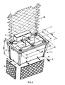
- the volume between the outer wall 1b and the inner wall 1a constitutes the water reserve 3.
- the inner wall 1a is sealed, so that the substrate of the tray 2 is not in contact with the water of the reserve 3.
- a substantially horizontal upper edge 1c connects the outer wall 1b to the inner wall 1a.
- This flange comprises at least one orifice for filling the water reserve 3.
- the main tank can have the following dimensions of about 30 to 75 liters of water and 4 to 15 liters for the substrate, which allows to obtain a range of one month minimum, at a rate of 0.5 to 1.5 liters of consumption per day.
- This double-walled tank therefore provides a large volume for a water reserve, which guarantees a much greater autonomy than that of commercial bins.
- the double wall 1a, 1b improves the isolation of the roots of the plant vis-à-vis the differences in ambient temperature.
- the tray 2 for the substrate can be divided into the medium in several portions that can receive substrates of different nature. This subdivision may for example be carried out at means of a partition 22, for example slid into corresponding grooves provided on the inner walls of the tray 2.
- tray 2 empty substrate one or more simple pots (transport jars) containing plants (such as marketed garden center or nursery), nested in the tray, provided that their dimensions are adapted at the baccalaureate.
- simple pots transport jars
- plants such as marketed garden center or nursery
- an orifice 23 provided with a grid to retain the substrate but to let an excess of water directly outside the tank.
- the water of the reserve 3 is insulated by a seal 24 of the substrate of the tank 2 (in the case where the main tank 1 is made in two parts).
- the pump 31 is controlled by an electronic module, itself powered by any appropriate means.
- electronic module and batteries can be arranged in a sealed housing 40, provided for this purpose in the rim of the main tray, or in a housing of the additional tank 4, and connected to the pump by means of an electric wire 44 housed in a waterproof sheath.
- a solar collector can be arranged on the main tank and the pump can then be powered by a battery system associated with solar energy.
- the device according to the invention can be made of any suitable material in contact with water and earth.
- the main tray 1 and the additional tank 4 may be made of thermoplastic material (for example, polyethylene or polypropylene), which has the following advantages: low cost, lightness, impact resistance, freedom of the shapes that can be achieved ...
- thermoplastic material for example, polyethylene or polypropylene
- the tray 1 can be made of several parts, for example in the form of a large tray whose envelope is defined by the outer wall 1b, and a small tray whose envelope is defined by the inner wall 1a, and equipped with a peripheral edge 1c allowing it to be placed on the edge of the large bin.
- the double walled main pan can be advantageously manufactured in one piece, by a suitable method such as blowing or rotomolding.
- the thickness of the walls is of the order of 3 mm to 5 mm.
- the tray 1 can be used as a molding die, simply requiring the drilling of at least one orifice for inserting the pump into the reserve 3 and an orifice for filling the reserve.
- the additional water tank can be manufactured with the main tank and then cut to make it available in its position of use. This minimizes the number of molds and molding operations.
- the reserve 3 has in its central part a boss on which bears the lower face of the tray 2, which allows to stiffen the structure and to center the two elements.
- an O-ring 24 is placed between the two parts so as to prevent the water of the reserve from leaking through the gap and back into the substrate 20 through the orifice 23.
- the main tray can receive, on one or more of its sides, skins of appearance 14 of varied colors and textures.
- These appearance skins are typically in the form of flat or curved plates, whose length and width are slightly smaller than those of the sides of the main tray. These plates can be themselves the appearance skin with a texture and an integrated color. They can be made of different materials (plastic, metal, terracotta, ......). These plates can also be simple support plates, on which it is possible for example to stick to or to bring back by any other means of connection (overmolding, welding, clipping, screwing, ....), wallpaper , wooden cannets, paintings, pebbles ...
- the tray can be decorated according to the taste of the user and contribute as such to the decor.
- the main tray has, on its outer wall, means for fixing the appearance skin.
- the appearance skin has an upper edge which can fit under a lip provided for this purpose on the main tray.
- the appearance skins can be secured to the tray, in their lower part, for example by means of screws 15 or any other removable attachment means.
- the bottom of the tray 1 can advantageously be provided with rollers 11, which allow to move it more easily.
- rollers 11 which allow to move it more easily.
- handles can be arranged reported or integrated to move the tray.
- the tray 1 can also be equipped with a palisade 16 which allows to grow climbing plants.
- the palisade 16 will for example also be made of plastic or wood, with amounts whose base is threaded, and adapted to be screwed into tapped holes located on one of the horizontal edges of the main tray 1.
- the bottom of the main tray may also include interlocking shapes on the upper rim of the tray, or studs 12 projecting from the bottom, forming feet - preferably four in number; the upper flange 1c then comprises housings 13 able to receive studs 12 'of a second tray 1' similar to tray 1.
- the tank may be equipped with means for indicating the water level in the reserve 3. It may be, in a conventional manner, a transparent portion of the outer wall of the tank, which allows a visual control of the water level in the reserve.
- the buzzer can be put into action, and also stop the operation. of the pump to avoid damaging it due to lack of water in the main tank.
- the major benefits of continuous drip watering are in the significantly improved plant health, reduced water consumption and reduced substrate volume. , the eradication of mosquito larvae (no stagnant water in contact with the surrounding air), and the reduction of phytosanitary treatments, harmful to humans.
Landscapes
- Engineering & Computer Science (AREA)
- Water Supply & Treatment (AREA)
- Life Sciences & Earth Sciences (AREA)
- Environmental Sciences (AREA)
- Cultivation Receptacles Or Flower-Pots, Or Pots For Seedlings (AREA)
- Hydroponics (AREA)
- Crystals, And After-Treatments Of Crystals (AREA)
- Glass Compositions (AREA)
Claims (10)
- Einheit zum Züchten von Pflanzen mit einem Behälter (2) für ein Wachstumssubstrat (20) einer Pflanze und einem ersten Wasservorratstank (3), dadurch gekennzeichnet, dass sie einen zusätzlichen Wasservorratstank (4) mit einem geringeren Fassungsvermögen als der erste Vorratstank enthält, der oberhalb der Oberfläche (21) des Substrats (20) in Strömungsverbindung mit dem ersten Wasservorratstank (3) angeordnet und mit einer Vorrichtung zum Befördern des Wasser ausgestattet ist, sowie mit einer Vorrichtung (5) zum ununterbrochenen Gießen der Pflanze durch die Schwerkraft ausgehend vom besagten zusätzlichen Wasservorratstank (4).
- Einheit nach Anspruch 1, dadurch gekennzeichnet, dass der zusätzliche Wasservorratstank (4) vom ersten Vorratstank (3) über eine Pumpe (31) mit Wasser versorgt wird.
- Einheit nach Anspruch 2, dadurch gekennzeichnet, dass die Pumpe (31) in den ersten Vorratstank (3) eingetaucht ist oder eine nicht eingetauchte selbstansaugende Pumpe mit einer Kapillare ist, die in den Vorratstank (3) eingetaucht wird.
- Einheit nach einem der Ansprüche 2 oder 3, dadurch gekennzeichnet, dass sie eine Steuervorrichtung (40) für die Pumpe (31) enthält, die in der Lage ist, den Betrieb der Pumpe zu bestimmten Zeitpunkten anzusteuern.
- Einheit nach Anspruch 1, dadurch gekennzeichnet, dass die Gießvorrichtung (5) einen Tropfer (51) enthält, sodass die Pflanze durch eine permanente Tröpfchenbewässerung gegossen wird.
- Einheit nach Anspruch 1, dadurch gekennzeichnet, dass sie eine Vorrichtung zur Anzeige des Wasserstandes im ersten Wasservorratstank (3) enthält.
- Einheit nach Anspruch 1, dadurch gekennzeichnet, dass sie einen Hauptbehälter (1) mit einer Doppelwand (1 a, 1 b) enthält, in dem:- der Behälter (2) für das Substrat dem Volumen entspricht, das von der Innenwand (1a) des Hauptbehälters (1) gebildet wird- der erste Wasservorratstank (3) dem Volumen entspricht, das zwischen der Innenwand (1a) und der Außenwand (1b) des Hauptbehälters (1) enthalten ist.
- Einheit nach Anspruch 7, dadurch gekennzeichnet, dass die Innenwand (1a) dicht ist, sodass der Behälter (2), in dem das Substrat enthalten ist, gegenüber dem ersten Wasservorratstank (3) abgedichtet wird.
- Einheit nach einem der Ansprüche 7 oder 8, dadurch gekennzeichnet, dass der Hauptbehälter (1) an seiner Außenseite zumindest eine auswechselbare Hülle in einer Erscheinungsform (14) enthält, anhand derer man eine globale modulare ästhetische Einheit erhalten kann.
- Einheit nach einem der Ansprüche 7 bis 9, dadurch gekennzeichnet, dass der Boden des Hauptbehälters (1) an seiner Außenseite Stifte (12) enthält, und dadurch, dass der obere Rand (1c) des Hauptbehälters (1) Aufnahmen (13) enthält, die in der Lage sind, die Stifte (12') eines zweiten Behälters (1') aufzunehmen, der dem besagten Behälter (1) ähnelt.
Applications Claiming Priority (1)
| Application Number | Priority Date | Filing Date | Title |
|---|---|---|---|
| FR0800033A FR2926003B1 (fr) | 2008-01-04 | 2008-01-04 | Dispositif pour la culture de vegetaux comprenant un bac pour substrat et une reserve d'eau pour arrosage par gravite |
Publications (2)
| Publication Number | Publication Date |
|---|---|
| EP2077068A1 EP2077068A1 (de) | 2009-07-08 |
| EP2077068B1 true EP2077068B1 (de) | 2011-03-02 |
Family
ID=39681005
Family Applications (1)
| Application Number | Title | Priority Date | Filing Date |
|---|---|---|---|
| EP08291251A Not-in-force EP2077068B1 (de) | 2008-01-04 | 2008-12-30 | Vorrichtung zur Pflanzenkultivierung |
Country Status (6)
| Country | Link |
|---|---|
| EP (1) | EP2077068B1 (de) |
| AT (1) | ATE499830T1 (de) |
| DE (1) | DE602008005248D1 (de) |
| ES (1) | ES2362381T3 (de) |
| FR (1) | FR2926003B1 (de) |
| PT (1) | PT2077068E (de) |
Cited By (1)
| Publication number | Priority date | Publication date | Assignee | Title |
|---|---|---|---|---|
| WO2021096046A1 (en) * | 2019-11-12 | 2021-05-20 | Lg Electronics Inc. | Plant cultivation apparatus and method of detecting error occurrence in the plant cultivation apparatus |
Families Citing this family (4)
| Publication number | Priority date | Publication date | Assignee | Title |
|---|---|---|---|---|
| CN103053357A (zh) * | 2013-01-17 | 2013-04-24 | 李吉世 | 一种智能型花盆 |
| US20150237814A1 (en) * | 2014-02-21 | 2015-08-27 | Broker Alliance Network, Inc. | Automated tree and plant watering system |
| FR3055180B1 (fr) * | 2016-08-31 | 2018-09-28 | Biopratic | Dispositif pour la culture de plantes, en particulier de plantes potageres |
| FR3070575B1 (fr) * | 2017-09-06 | 2020-04-03 | Maxence Rochefort | Systeme d'alimentation en eau pour plante |
Family Cites Families (8)
| Publication number | Priority date | Publication date | Assignee | Title |
|---|---|---|---|---|
| US650614A (en) * | 1899-02-21 | 1900-05-29 | Alexander Roeseler | Flower-pot. |
| ES425543A1 (es) * | 1974-04-20 | 1976-06-16 | Martinez Martinez | Sistema automatico perfeccionado de riego para macetas, jardineras y plantas en el suelo. |
| DE8808877U1 (de) * | 1988-07-11 | 1988-09-08 | Hong, Jue-Jong, Panchiao | Gewächskasten |
| US5136807A (en) * | 1990-01-26 | 1992-08-11 | Gro-Max Systems, Inc. | Arrangement for growing plants |
| AU7821591A (en) * | 1990-06-10 | 1991-12-12 | Gro-Max Systems, Inc. | Column planter |
| DE9006988U1 (de) * | 1990-06-22 | 1991-10-17 | Fischer, Klaus, 8440 Straubing | Bewässerungsanlage |
| US6622430B1 (en) * | 2002-06-17 | 2003-09-23 | Yuan-Song Lai | Flowerpot |
| US7607257B2 (en) | 2005-03-29 | 2009-10-27 | Leonard Goldberg | Automatic watering apparatus for houseplants |
-
2008
- 2008-01-04 FR FR0800033A patent/FR2926003B1/fr not_active Expired - Fee Related
- 2008-12-30 DE DE602008005248T patent/DE602008005248D1/de active Active
- 2008-12-30 PT PT08291251T patent/PT2077068E/pt unknown
- 2008-12-30 AT AT08291251T patent/ATE499830T1/de active
- 2008-12-30 EP EP08291251A patent/EP2077068B1/de not_active Not-in-force
- 2008-12-30 ES ES08291251T patent/ES2362381T3/es active Active
Cited By (1)
| Publication number | Priority date | Publication date | Assignee | Title |
|---|---|---|---|---|
| WO2021096046A1 (en) * | 2019-11-12 | 2021-05-20 | Lg Electronics Inc. | Plant cultivation apparatus and method of detecting error occurrence in the plant cultivation apparatus |
Also Published As
| Publication number | Publication date |
|---|---|
| ATE499830T1 (de) | 2011-03-15 |
| PT2077068E (pt) | 2011-06-08 |
| EP2077068A1 (de) | 2009-07-08 |
| FR2926003B1 (fr) | 2012-11-02 |
| DE602008005248D1 (de) | 2011-04-14 |
| ES2362381T3 (es) | 2011-07-04 |
| FR2926003A1 (fr) | 2009-07-10 |
Similar Documents
| Publication | Publication Date | Title |
|---|---|---|
| EP2077068A1 (de) | Vorrichtung zur Pflanzenkultivierung | |
| EP3544410B1 (de) | Pflanzenzuchtvorrichtung | |
| FR2701352A1 (fr) | Dispositif d'auto-arrosage pour cultures en pots ou similaires. | |
| FR2913303A1 (fr) | Dispositif de culture hors sol | |
| EP4108075B1 (de) | Vorrichtung zur wasserversorgung von mindestens einer pflanze, insbesondere einer gemüsepflanze, und anlage mit mindestens einer solchen vorrichtung | |
| FR2543794A1 (fr) | Dispositif autonome d'irrigation | |
| FR2501961A1 (fr) | Cache-pot a reservoir avec dispositif d'irrigation de la plante mise en terre dans le pot | |
| EP1790214B1 (de) | Pflanztopf | |
| BE1011658A3 (fr) | Bac de forcage hydroponique pour la culture des endives et installation de forcage hydroponique. | |
| FR2956282A1 (fr) | Structure pour la culture vegetale | |
| WO2019185534A1 (fr) | Dispositif de culture hors-sol a structure verticale et contenant pour plante | |
| FR2663193A1 (fr) | Dispositif de culture de plantes en pot, a grande reserve d'eau. | |
| FR3152208A1 (fr) | Recipient de culture de vegetaux muni d’un dispositif de sonorisation | |
| EP3874939A1 (de) | Vorrichtung zur luft- und wasserversorgung der wurzeln von pflanzen in erdloser kultur | |
| FR2976769A1 (fr) | Tableau vegetal | |
| FR2458994A1 (fr) | Dispositif irrigateur autonome pour plantes | |
| FR2932359A1 (fr) | Dispositif permettant la culture des vegetaux. | |
| EP1064841B1 (de) | Blumentopfeinrichtung mit Wasservorrat | |
| FR3158609A1 (fr) | Jardinière bioclimatique destinée à la culture de végétaux | |
| EP4588339A1 (de) | Zubehör zur zumindest teilweisen aufnahme einer pflanze und vorrichtung mit solch einem zubehör | |
| EP0075636A1 (de) | Bewässerungsvorrichtung für Pflanzen in Gefässen | |
| EP4331350A1 (de) | Kulturvorrichtung | |
| FR2595535A1 (fr) | Bac a fleurs, a plantes ou autres avec reserve d'eau | |
| FR2763791A1 (fr) | Dispositif d'arrosage pour les vegetaux | |
| WO1992019097A1 (fr) | Dispositif autonome programmable d'arrosage de plantes en pot |
Legal Events
| Date | Code | Title | Description |
|---|---|---|---|
| PUAI | Public reference made under article 153(3) epc to a published international application that has entered the european phase |
Free format text: ORIGINAL CODE: 0009012 |
|
| AK | Designated contracting states |
Kind code of ref document: A1 Designated state(s): AT BE BG CH CY CZ DE DK EE ES FI FR GB GR HR HU IE IS IT LI LT LU LV MC MT NL NO PL PT RO SE SI SK TR |
|
| AX | Request for extension of the european patent |
Extension state: AL BA MK RS |
|
| 17P | Request for examination filed |
Effective date: 20091223 |
|
| AKX | Designation fees paid |
Designated state(s): AT BE BG CH CY CZ DE DK EE ES FI FR GB GR HR HU IE IS IT LI LT LU LV MC MT NL NO PL PT RO SE SI SK TR |
|
| GRAP | Despatch of communication of intention to grant a patent |
Free format text: ORIGINAL CODE: EPIDOSNIGR1 |
|
| GRAS | Grant fee paid |
Free format text: ORIGINAL CODE: EPIDOSNIGR3 |
|
| GRAA | (expected) grant |
Free format text: ORIGINAL CODE: 0009210 |
|
| AK | Designated contracting states |
Kind code of ref document: B1 Designated state(s): AT BE BG CH CY CZ DE DK EE ES FI FR GB GR HR HU IE IS IT LI LT LU LV MC MT NL NO PL PT RO SE SI SK TR |
|
| REG | Reference to a national code |
Ref country code: GB Ref legal event code: FG4D Free format text: NOT ENGLISH |
|
| REG | Reference to a national code |
Ref country code: CH Ref legal event code: EP |
|
| REG | Reference to a national code |
Ref country code: IE Ref legal event code: FG4D Free format text: LANGUAGE OF EP DOCUMENT: FRENCH |
|
| REF | Corresponds to: |
Ref document number: 602008005248 Country of ref document: DE Date of ref document: 20110414 Kind code of ref document: P |
|
| REG | Reference to a national code |
Ref country code: DE Ref legal event code: R096 Ref document number: 602008005248 Country of ref document: DE Effective date: 20110414 |
|
| REG | Reference to a national code |
Ref country code: PT Ref legal event code: SC4A Free format text: AVAILABILITY OF NATIONAL TRANSLATION Effective date: 20110601 |
|
| REG | Reference to a national code |
Ref country code: CH Ref legal event code: NV Representative=s name: P&TS SA |
|
| REG | Reference to a national code |
Ref country code: NL Ref legal event code: T3 |
|
| REG | Reference to a national code |
Ref country code: ES Ref legal event code: FG2A Ref document number: 2362381 Country of ref document: ES Kind code of ref document: T3 Effective date: 20110704 |
|
| PG25 | Lapsed in a contracting state [announced via postgrant information from national office to epo] |
Ref country code: LT Free format text: LAPSE BECAUSE OF FAILURE TO SUBMIT A TRANSLATION OF THE DESCRIPTION OR TO PAY THE FEE WITHIN THE PRESCRIBED TIME-LIMIT Effective date: 20110302 Ref country code: HR Free format text: LAPSE BECAUSE OF FAILURE TO SUBMIT A TRANSLATION OF THE DESCRIPTION OR TO PAY THE FEE WITHIN THE PRESCRIBED TIME-LIMIT Effective date: 20110302 Ref country code: SE Free format text: LAPSE BECAUSE OF FAILURE TO SUBMIT A TRANSLATION OF THE DESCRIPTION OR TO PAY THE FEE WITHIN THE PRESCRIBED TIME-LIMIT Effective date: 20110302 Ref country code: GR Free format text: LAPSE BECAUSE OF FAILURE TO SUBMIT A TRANSLATION OF THE DESCRIPTION OR TO PAY THE FEE WITHIN THE PRESCRIBED TIME-LIMIT Effective date: 20110603 Ref country code: LV Free format text: LAPSE BECAUSE OF FAILURE TO SUBMIT A TRANSLATION OF THE DESCRIPTION OR TO PAY THE FEE WITHIN THE PRESCRIBED TIME-LIMIT Effective date: 20110302 Ref country code: NO Free format text: LAPSE BECAUSE OF FAILURE TO SUBMIT A TRANSLATION OF THE DESCRIPTION OR TO PAY THE FEE WITHIN THE PRESCRIBED TIME-LIMIT Effective date: 20110602 |
|
| LTIE | Lt: invalidation of european patent or patent extension |
Effective date: 20110302 |
|
| PG25 | Lapsed in a contracting state [announced via postgrant information from national office to epo] |
Ref country code: CY Free format text: LAPSE BECAUSE OF FAILURE TO SUBMIT A TRANSLATION OF THE DESCRIPTION OR TO PAY THE FEE WITHIN THE PRESCRIBED TIME-LIMIT Effective date: 20110302 Ref country code: BG Free format text: LAPSE BECAUSE OF FAILURE TO SUBMIT A TRANSLATION OF THE DESCRIPTION OR TO PAY THE FEE WITHIN THE PRESCRIBED TIME-LIMIT Effective date: 20110602 Ref country code: FI Free format text: LAPSE BECAUSE OF FAILURE TO SUBMIT A TRANSLATION OF THE DESCRIPTION OR TO PAY THE FEE WITHIN THE PRESCRIBED TIME-LIMIT Effective date: 20110302 Ref country code: SI Free format text: LAPSE BECAUSE OF FAILURE TO SUBMIT A TRANSLATION OF THE DESCRIPTION OR TO PAY THE FEE WITHIN THE PRESCRIBED TIME-LIMIT Effective date: 20110302 |
|
| REG | Reference to a national code |
Ref country code: IE Ref legal event code: FD4D |
|
| PG25 | Lapsed in a contracting state [announced via postgrant information from national office to epo] |
Ref country code: EE Free format text: LAPSE BECAUSE OF FAILURE TO SUBMIT A TRANSLATION OF THE DESCRIPTION OR TO PAY THE FEE WITHIN THE PRESCRIBED TIME-LIMIT Effective date: 20110302 Ref country code: IE Free format text: LAPSE BECAUSE OF FAILURE TO SUBMIT A TRANSLATION OF THE DESCRIPTION OR TO PAY THE FEE WITHIN THE PRESCRIBED TIME-LIMIT Effective date: 20110302 |
|
| PG25 | Lapsed in a contracting state [announced via postgrant information from national office to epo] |
Ref country code: CZ Free format text: LAPSE BECAUSE OF FAILURE TO SUBMIT A TRANSLATION OF THE DESCRIPTION OR TO PAY THE FEE WITHIN THE PRESCRIBED TIME-LIMIT Effective date: 20110302 Ref country code: IS Free format text: LAPSE BECAUSE OF FAILURE TO SUBMIT A TRANSLATION OF THE DESCRIPTION OR TO PAY THE FEE WITHIN THE PRESCRIBED TIME-LIMIT Effective date: 20110702 Ref country code: SK Free format text: LAPSE BECAUSE OF FAILURE TO SUBMIT A TRANSLATION OF THE DESCRIPTION OR TO PAY THE FEE WITHIN THE PRESCRIBED TIME-LIMIT Effective date: 20110302 Ref country code: RO Free format text: LAPSE BECAUSE OF FAILURE TO SUBMIT A TRANSLATION OF THE DESCRIPTION OR TO PAY THE FEE WITHIN THE PRESCRIBED TIME-LIMIT Effective date: 20110302 |
|
| PLBE | No opposition filed within time limit |
Free format text: ORIGINAL CODE: 0009261 |
|
| STAA | Information on the status of an ep patent application or granted ep patent |
Free format text: STATUS: NO OPPOSITION FILED WITHIN TIME LIMIT |
|
| 26N | No opposition filed |
Effective date: 20111205 |
|
| PG25 | Lapsed in a contracting state [announced via postgrant information from national office to epo] |
Ref country code: DK Free format text: LAPSE BECAUSE OF FAILURE TO SUBMIT A TRANSLATION OF THE DESCRIPTION OR TO PAY THE FEE WITHIN THE PRESCRIBED TIME-LIMIT Effective date: 20110302 Ref country code: PL Free format text: LAPSE BECAUSE OF FAILURE TO SUBMIT A TRANSLATION OF THE DESCRIPTION OR TO PAY THE FEE WITHIN THE PRESCRIBED TIME-LIMIT Effective date: 20110302 |
|
| REG | Reference to a national code |
Ref country code: DE Ref legal event code: R097 Ref document number: 602008005248 Country of ref document: DE Effective date: 20111205 |
|
| PG25 | Lapsed in a contracting state [announced via postgrant information from national office to epo] |
Ref country code: MT Free format text: LAPSE BECAUSE OF FAILURE TO SUBMIT A TRANSLATION OF THE DESCRIPTION OR TO PAY THE FEE WITHIN THE PRESCRIBED TIME-LIMIT Effective date: 20110302 |
|
| PG25 | Lapsed in a contracting state [announced via postgrant information from national office to epo] |
Ref country code: LU Free format text: LAPSE BECAUSE OF NON-PAYMENT OF DUE FEES Effective date: 20111230 |
|
| REG | Reference to a national code |
Ref country code: FR Ref legal event code: CL Name of requester: TMP CONVERT, FR Effective date: 20130627 |
|
| PG25 | Lapsed in a contracting state [announced via postgrant information from national office to epo] |
Ref country code: TR Free format text: LAPSE BECAUSE OF FAILURE TO SUBMIT A TRANSLATION OF THE DESCRIPTION OR TO PAY THE FEE WITHIN THE PRESCRIBED TIME-LIMIT Effective date: 20110302 |
|
| PG25 | Lapsed in a contracting state [announced via postgrant information from national office to epo] |
Ref country code: HU Free format text: LAPSE BECAUSE OF FAILURE TO SUBMIT A TRANSLATION OF THE DESCRIPTION OR TO PAY THE FEE WITHIN THE PRESCRIBED TIME-LIMIT Effective date: 20110302 |
|
| PGFP | Annual fee paid to national office [announced via postgrant information from national office to epo] |
Ref country code: PT Payment date: 20131220 Year of fee payment: 6 Ref country code: CH Payment date: 20131219 Year of fee payment: 6 Ref country code: GB Payment date: 20131227 Year of fee payment: 6 Ref country code: AT Payment date: 20131210 Year of fee payment: 6 Ref country code: MC Payment date: 20131223 Year of fee payment: 6 |
|
| PGFP | Annual fee paid to national office [announced via postgrant information from national office to epo] |
Ref country code: NL Payment date: 20131210 Year of fee payment: 6 |
|
| PGFP | Annual fee paid to national office [announced via postgrant information from national office to epo] |
Ref country code: BE Payment date: 20131217 Year of fee payment: 6 |
|
| PG25 | Lapsed in a contracting state [announced via postgrant information from national office to epo] |
Ref country code: BE Free format text: LAPSE BECAUSE OF NON-PAYMENT OF DUE FEES Effective date: 20141231 |
|
| REG | Reference to a national code |
Ref country code: PT Ref legal event code: MM4A Free format text: LAPSE DUE TO NON-PAYMENT OF FEES Effective date: 20150630 |
|
| REG | Reference to a national code |
Ref country code: NL Ref legal event code: V1 Effective date: 20150701 |
|
| REG | Reference to a national code |
Ref country code: NL Ref legal event code: V1 Effective date: 20150701 |
|
| PG25 | Lapsed in a contracting state [announced via postgrant information from national office to epo] |
Ref country code: PT Free format text: LAPSE BECAUSE OF NON-PAYMENT OF DUE FEES Effective date: 20150630 |
|
| REG | Reference to a national code |
Ref country code: CH Ref legal event code: PL |
|
| REG | Reference to a national code |
Ref country code: AT Ref legal event code: MM01 Ref document number: 499830 Country of ref document: AT Kind code of ref document: T Effective date: 20141230 |
|
| GBPC | Gb: european patent ceased through non-payment of renewal fee |
Effective date: 20141230 |
|
| PG25 | Lapsed in a contracting state [announced via postgrant information from national office to epo] |
Ref country code: NL Free format text: LAPSE BECAUSE OF NON-PAYMENT OF DUE FEES Effective date: 20150701 |
|
| PG25 | Lapsed in a contracting state [announced via postgrant information from national office to epo] |
Ref country code: GB Free format text: LAPSE BECAUSE OF NON-PAYMENT OF DUE FEES Effective date: 20141230 Ref country code: CH Free format text: LAPSE BECAUSE OF NON-PAYMENT OF DUE FEES Effective date: 20141231 Ref country code: LI Free format text: LAPSE BECAUSE OF NON-PAYMENT OF DUE FEES Effective date: 20141231 |
|
| PG25 | Lapsed in a contracting state [announced via postgrant information from national office to epo] |
Ref country code: AT Free format text: LAPSE BECAUSE OF NON-PAYMENT OF DUE FEES Effective date: 20141230 |
|
| REG | Reference to a national code |
Ref country code: FR Ref legal event code: PLFP Year of fee payment: 8 |
|
| PG25 | Lapsed in a contracting state [announced via postgrant information from national office to epo] |
Ref country code: MC Free format text: LAPSE BECAUSE OF NON-PAYMENT OF DUE FEES Effective date: 20141231 |
|
| REG | Reference to a national code |
Ref country code: FR Ref legal event code: PLFP Year of fee payment: 9 |
|
| PGFP | Annual fee paid to national office [announced via postgrant information from national office to epo] |
Ref country code: IT Payment date: 20161214 Year of fee payment: 9 Ref country code: ES Payment date: 20161229 Year of fee payment: 9 Ref country code: FR Payment date: 20161222 Year of fee payment: 9 |
|
| PGFP | Annual fee paid to national office [announced via postgrant information from national office to epo] |
Ref country code: DE Payment date: 20161221 Year of fee payment: 9 |
|
| REG | Reference to a national code |
Ref country code: DE Ref legal event code: R119 Ref document number: 602008005248 Country of ref document: DE |
|
| REG | Reference to a national code |
Ref country code: FR Ref legal event code: ST Effective date: 20180831 |
|
| PG25 | Lapsed in a contracting state [announced via postgrant information from national office to epo] |
Ref country code: IT Free format text: LAPSE BECAUSE OF NON-PAYMENT OF DUE FEES Effective date: 20171230 Ref country code: DE Free format text: LAPSE BECAUSE OF NON-PAYMENT OF DUE FEES Effective date: 20180703 Ref country code: FR Free format text: LAPSE BECAUSE OF NON-PAYMENT OF DUE FEES Effective date: 20180102 |
|
| REG | Reference to a national code |
Ref country code: ES Ref legal event code: FD2A Effective date: 20190704 |
|
| PG25 | Lapsed in a contracting state [announced via postgrant information from national office to epo] |
Ref country code: ES Free format text: LAPSE BECAUSE OF NON-PAYMENT OF DUE FEES Effective date: 20171231 |