EP2077100A1 - Tamponapplikator - Google Patents
Tamponapplikator Download PDFInfo
- Publication number
- EP2077100A1 EP2077100A1 EP09158588A EP09158588A EP2077100A1 EP 2077100 A1 EP2077100 A1 EP 2077100A1 EP 09158588 A EP09158588 A EP 09158588A EP 09158588 A EP09158588 A EP 09158588A EP 2077100 A1 EP2077100 A1 EP 2077100A1
- Authority
- EP
- European Patent Office
- Prior art keywords
- valves
- outer cylinder
- applicator
- tampon
- diameter portion
- Prior art date
- Legal status (The legal status is an assumption and is not a legal conclusion. Google has not performed a legal analysis and makes no representation as to the accuracy of the status listed.)
- Granted
Links
Images


Classifications
-
- A—HUMAN NECESSITIES
- A61—MEDICAL OR VETERINARY SCIENCE; HYGIENE
- A61F—FILTERS IMPLANTABLE INTO BLOOD VESSELS; PROSTHESES; DEVICES PROVIDING PATENCY TO, OR PREVENTING COLLAPSING OF, TUBULAR STRUCTURES OF THE BODY, e.g. STENTS; ORTHOPAEDIC, NURSING OR CONTRACEPTIVE DEVICES; FOMENTATION; TREATMENT OR PROTECTION OF EYES OR EARS; BANDAGES, DRESSINGS OR ABSORBENT PADS; FIRST-AID KITS
- A61F13/00—Bandages or dressings; Absorbent pads
- A61F13/15—Absorbent pads, e.g. sanitary towels, swabs or tampons for external or internal application to the body; Supporting or fastening means therefor; Tampon applicators
- A61F13/20—Tampons, e.g. catamenial tampons; Accessories therefor
- A61F13/26—Means for inserting tampons, i.e. applicators
-
- A—HUMAN NECESSITIES
- A61—MEDICAL OR VETERINARY SCIENCE; HYGIENE
- A61F—FILTERS IMPLANTABLE INTO BLOOD VESSELS; PROSTHESES; DEVICES PROVIDING PATENCY TO, OR PREVENTING COLLAPSING OF, TUBULAR STRUCTURES OF THE BODY, e.g. STENTS; ORTHOPAEDIC, NURSING OR CONTRACEPTIVE DEVICES; FOMENTATION; TREATMENT OR PROTECTION OF EYES OR EARS; BANDAGES, DRESSINGS OR ABSORBENT PADS; FIRST-AID KITS
- A61F13/00—Bandages or dressings; Absorbent pads
- A61F13/15—Absorbent pads, e.g. sanitary towels, swabs or tampons for external or internal application to the body; Supporting or fastening means therefor; Tampon applicators
- A61F13/20—Tampons, e.g. catamenial tampons; Accessories therefor
Definitions
- the present invention relates to an applicator for a tampon to be employed when a sanitary tampon is to be inserted into a human body.
- the applicator for the sanitary tampon is constructed to include an outer cylinder for fitting the tampon therein, and an inner cylinder inserted into the outer cylinder and protruding rearwardly from the rear end of the outer cylinder.
- a take-out cord extending from the tampon, is led out of the outer cylinder through the inner cylinder and protruded, rearwardly from a rear end of the inner cylinder.
- the outer cylinder When the tampon is to be employed, the outer cylinder is inserted into a vaginal cavity, and the inner cylinder is pushed to push the tampon out of the outer cylinder. Then, the tampon is inserted into the vaginal cavity while expanding a number of deformable valves at the leading end of the outer cylinder.
- Some of the existing applicators are formed to have an outer cylinder and an inner cylinder which are made of paper.
- an outer cylinder injection-molded of a synthetic resin has been employed so that it may have a smooth surface and may be smoothly inserted into the vaginal cavity.
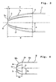
- Fig. 4 is a partial side elevation showing an ordinary shape of the leading end portion of an outer cylinder 30 of a conventional applicator.
- the outer cylinder 30 of the conventional applicator is constructed to include a cylindrical large diameter portion 30a, and a curved face portion 30b is formed on the side of the leading portion with respect to the large diameter portion 30a through an inflection point Zo.
- the curved face portion 30b is formed into a generally semispherical shape which has a radial center located at the center 0 of the section extending through the inflection point Zo. Therefore, a ratio Ao/Bo is about 1, if the radius of the outer periphery at the inflection point Zo is designated by Ao and the axial length from the inflection point Zo to the leading end of the curved face portion 30b is designated by Bo.
- valves 31 In the curved face portion 30b, there are formed a plurality of valves 31 extending toward the leading end and arranged in a petal shape. These valves 31 are deformed to converge toward the leading end at the curvature of the curved face portion 30b.
- the large diameter portion 30a has the cylindrical shape, and the semispherical curved face portion 30b is formed at the leading end of the large diameter portion 30a. Accordingly, upon using the applicator, this shape exerts restrictions on the reduction of the resistance to the insertion into the vaginal cavity.
- the resistance to the insertion into the vaginal cavity could be reduced, if the leading end of the outer cylinder was formed not into the semispherical shape but into the shape in which the diameter is gradually reduced toward the leading portion, that is, in which the ratio Ao/Bo is smaller than 1.
- the valves 31 have to be accordingly elongated in the axial direction. If the axial length size of the valves is thus enlarged at the leading portion of the outer cylinder, the shape of the leading ends of the valves is not stabilized but may be deformed to open the leading ends of the valves when the valves are thermally deformed into the curved face shape with the tampon being fitted in the outer cylinder. If the valves are opened, the leading portion of the outer cylinder may give an unnecessary resistance to the human body or may damage the body when the leading portion of the outer cylinder is inserted into the vaginal cavity.
- valves each having a long axial length and to stabilize the shape of the thermally deformed valves
- the amount of resin to be employed increases to cause a problem that the environment is adversely affected by the dumped resin.
- the hard resin is employed, the values become hard to increase the contact resistance to the body. Furthermore, the fluidity of the resin in the injection mold is reduced to easily cause the defective molding of the valves and the like.
- the invention has an object to provide an applicator for a tampon in which valves provided at the leading portion can be easily molded and can be prevented from opening at the leading ends, when the leading portion of an outer cylinder thereof is shaped to be easily inserted into a vaginal cavity.
- an applicator for a tampon may comprise: an outer cylinder including a large diameter portion for fitting a tampon therein, a small diameter portion provided on the side of a rear end of the outer cylinder and having a smaller diameter than that of the large diameter portion, and a plurality of valves provided on the side of a leading end of the outer cylinder, the valves being converged to have a curved face portion to be diametrically gradually reduced toward the leading end of the outer cylinder; and a push-out member movably inserted into the small diameter portion of the outer cylinder, wherein a ratio A/B is at most 0.8, when an inflection point for the boundary between the maximum diameter portion of the large diameter portion and the curved face portion is designated by Z, a radius of the outer face at the inflection point Z is designated by A, and the axial length from the inflection point Z to the leading end of the curved face portion is designated by B, and wherein a ratio L/W is
- the curved face portion of the leading portion is shaped such that the ratio A/B is at most 0.8, so that it is possible to reduce the resistance to the insertion into the vaginal cavity in comparison with the conventional outer cylinder having the semispherical curved face portion as shown in Fig. 4 .
- valves will be elongated in the axial direction of the outer cylinder.
- the force for holding the resin distortion upon thermally deforming the valves into a curved face shape can be intensified to restrain the restoration so that the valves can be suppressed from being opened at their leading portions.
- the root ends of the valves are located substantially at the same position of the inflection point z.
- the curved face portion has two curvatures, and the curvature at the leading end portions of the valves is larger than that at the root ends of the valves.
- the axial length Y of the valve portions having the larger curvature is one half or less than the axial length B from the inflection point Z to the leading end of the curved face portion.
- the leading end portions of the valves are deformed at the large curvature, so that the plastic deformation of the leading end portions of the valves can be enlarged to further suppress opening of the leading ends of the valves. Since the leading end portions of the valves are formed to have the large curvature, they are prevented, when inserted into the human body, from abutting against the body, thereby giving no uncomfortable feeling to the body.
- Fig. 1 is a longitudinal section showing the state in which a tampon is fitted in an applicator according to the invention
- Fig. 2A is a side elevation showing the state in which an outer cylinder is injection-molded
- Fig. 2B is an end view of a leading portion of the outer cylinder
- Fig. 3 is an enlarged side elevation showing the state in which valves are curved.
- the applicator for a tampon is constructed to include an outer cylinder 1 and an inner cylinder 2 (or a push-out member).
- a tampon 3 which is formed by compress-molding absorptive fibers such as cotton.
- a take-out cord 4 which is extended rearwardly from the inside of the outer cylinder 1 through the inner cylinder 2.
- the outer cylinder 1 is injection-molded of a thermoplastic resin such as PE (polyethylene) or PP (polypropylene).
- the outer cylinder 1 thus injection-molded has a smooth surface to give little uncomfortable feeling when it comes into contact with the human body.
- the thermoplastic resin is preferably exemplified by the LDPE (i.e., low density polyethylene) when the outer cylinder 1 is injection-molded, so that the resin may flow without stagnation in the mold thereby to provide a smooth surface and a thickness as small as possible.
- the thickness of the outer cylinder 1 to be formed by the injection-molding is within a range of 0.6 mm to 1.0 mm.
- the inner cylinder 2 provided as a push-out member for pushing out the tampon 3 is formed of an extruded material by extrusion-molding the thermoplastic resin such as PE, PP or PET (i.e., polyethylene terephthalate) into a cylindrical shape (e.g., a straw shape or a pipe shape). More preferably, the extruded thermoplastic resin is oriented in the axial direction. The extruded material thus extrusion-molded and axially oriented is improved in the axial orientation so that its axial buckling strength is enhanced.
- the thermoplastic resin such as PE, PP or PET (i.e., polyethylene terephthalate) into a cylindrical shape (e.g., a straw shape or a pipe shape). More preferably, the extruded thermoplastic resin is oriented in the axial direction.
- the extruded material thus extrusion-molded and axially oriented is improved in the axial orientation so that its axial buckling strength is enhanced.
- the inner cylinder 2 Even if the thickness is made so small as 0.4 mm or less (up to about 0.1 mm) and the internal diameter is made so small as 7 mm or less (up to about 3 mm), the inner cylinder 2 retains a sufficient buckling strength. Accordingly, the inner cylinder 2 is hardly buckled or not folded, when the inner cylinder 2 is pushed to push out the tampon 3 from the outer cylinder 1 upon use.
- the inner cylinder 2 is movably inserted into a small diameter portion 8 of the outer cylinder 1 and has a push portion 11 at a leading end thereof.
- This push portion 11 is diverged to push the tampon 3 easily from its rear end and to prevent the inner cylinder 2 from being withdrawn from a rear end 9 of the outer cylinder 1.
- Fig. 2A shows the state in which the outer cylinder 1 is injection-molded.
- the outer cylinder 1 immediately after injection-molded has a cylindrical shape, in which a large diameter portion 7 has a constant external diameter. Between this large diameter portion 7 and the small diameter portion 8 on the rear side, there is formed an inflection plane 15 at which the external diameter gradually changes. Between the large diameter portion 7 and the small diameter portion 8, however, there may be formed a step, across which the external diameter of the outer cylinder 1 may be abruptly changed.
- valves 17 In the leading end of the large diameter portion 7, there is opened a protruding mouth 16, around which there are formed four valves 17 in a petal shape.
- the valves 17 are converged to have their width sizes reducing gradually toward the leading end of the outer cylinder 1 so that they have a generally conical shape at their leading ends.
- the valves 17 have a length L, as taken in the axial direction of the outer cylinder 1.
- the valves 17 have a width W at root ends thereof.
- the push portion 11 is firstly expanded at the leading end of the inner cylinder 2.
- the rear end of the inner cylinder 2 is inserted from the protruding mouth 16 of the outer cylinder 1 and is guided through the small diameter portion 8 until it is protruded rearwardly from an opening 10 in the rear end 9 of the outer cylinder 1.
- the diverging portion 12 is formed at the rear end of the inner cylinder 2 protruding rearwardly from the opening 10.
- the tampon 3 is inserted from the protruding mouth 16 into the large diameter portion 7 of the outer cylinder 1. At this time, the take-out cord 4 is pulled out through the inner cylinder 2 rearwardly from the rear end of the inner cylinder 2.
- a heated press die is applied to the leading portion of the large diameter portion 7 of the outer cylinder 1 to deform the valves 17 thermally.
- the valves 17 are deformed to converge toward the leading end so that a curved face portion 7a is formed on the outer cylinder 1 on the side of the leading portion with respect to the large diameter portion 7, as shown in Fig. 3 .
- the curved face portion 7a has a length B, as taken in the axial direction of the outer cylinder 1.
- the valves 17 having the length L as shown in Fig. 2A are curved and deformed to form the curved face portion 7a so that the ratio of B to L is B ⁇ L.
- the boundary between generally cylindrical large diameter portion 7 and the curved face portion 7a has a inflection point Z (or a first inflection point Z), which is located at a position substantially identical to the root ends of the valves 17 in the axial direction of the outer cylinder 1.
- a leading end portion 7b within a predetermined length range (i.e., a length range Y in the axial direction of the outer cylinder 1) from the leading end to the root end side of the valves 17 is formed to have a larger curvature than that of the curved face portion 7a closer to the root end side than the leading end portions 7b.
- a predetermined length range i.e., a length range Y in the axial direction of the outer cylinder 1
- the inflection point Z at which the large diameter portion 7 leads into the curved face portion 7a
- a second inflection point S which is located in front of the inflection point Z and leads into the leading end portions 7b.
- the leading end portion 7b in the range Y has a larger curvature than that of the curved face portion 7a in the range X on the root end side.
- a ratio A/B is at most 0.8, or preferably at most 0.6. Therefore, the curved face portion 7a is formed so as to converge toward the leading portion and is more slender than the curved semispherical face portion 30b of the conventional applicator shown in Fig. 4 . Accordingly, it is possible to reduce the resistance which might otherwise be felt when the leading portion of the outer cylinder 1 is inserted into the vaginal cavity.
- a ratio L/W between the length L of the valve 17 and the width W of the root end is set within a range of 1.0 to 2.0.
- the valves 17 are elongated so much as to reduce the amount of the resin being oriented in the curved state. Therefore, it is hard to keep the curved state so that the valves 17 easily restore their original shape after shaped and tend to open at the leading ends by the external force.
- the curvature of the leading end portions 7b is made larger than that of the curved face portion 7a in the range X.
- the curved deformation of the leading ends of the valves 17 can be enlarged to suppress the leading ends from opening.
- the valves 17 converge at their leading ends with the large curvature so that their leading ends are prevented from abutting against the human body when inserted into the vaginal cavity.
- the leading end portions 7b are preferably formed locally at the tips of the valves 17. Therefore, in the axial sizes of the outer cylinder 1, the relation between the length Y of the leading end portions 7b and the length X of the curved face portion 7a close to the root end side is preferably Y ⁇ X, i.e., the ratio Y/B is at most 0.5, or more preferably the ratio Y/B is at most 0.3.
- the employed resin was LDPE (i.e., low density polyethylene) having a density of 0.92 g/cm 3 and an MFR (i.e., melt flow rate) of 48.
- LDPE low density polyethylene
- MFR melt flow rate
- the outer cylinder having a shape similar to that shown in Fig. 2A was injection-molded, and the shape of the leading portions of the valves were observed.
- the outer cylinders were judged as defective moldings, as indicated by "X", if their leading ends were cut out or burred.
- the injection-molded outer cylinder was heated at its leading end with the die so that the valves were curved to form the curved face portion, and was left for one week in the oven of 40 °C. The opening of the leading ends of the valves was observed. The valves were judged to be defective, as indicated by "X", if their leading ends were deformed to outwardly open by 2 mm or more than those before left.
- Push-out Feasibility or Pushability
- the tampon was fitted in the applicator and was actually employed by the consumer.
- the resistance at the time when the tampon was pushed out by pushing the inner cylinder was tested.
- the tampon was judged to be defective, as indicated by "X", if the user felt it difficult to push out the tampon.
- Comparative Example 1 had the ratio L/W of 0.66 so that the leading portion was not converged to make it difficult to push the tampon.
- Comparative Example 2 had the ratio L/W over 2.0 so that the valves had a poor injection moldability and easily opened at their leading end.
- the curved face portion at the leading portion of the large diameter portion of the applicator is converged to be easily inserted into the vaginal cavity.
- the valves are prevented from being cut out or burred when injection-molded, and are hardly opened when curved. Furthermore, by enlarging the curvature of the leading end portions of the valves, it becomes easy to suppress opening of the leading ends of the valves.
Landscapes
- Health & Medical Sciences (AREA)
- Epidemiology (AREA)
- Engineering & Computer Science (AREA)
- Biomedical Technology (AREA)
- Heart & Thoracic Surgery (AREA)
- Vascular Medicine (AREA)
- Life Sciences & Earth Sciences (AREA)
- Animal Behavior & Ethology (AREA)
- General Health & Medical Sciences (AREA)
- Public Health (AREA)
- Veterinary Medicine (AREA)
- Absorbent Articles And Supports Therefor (AREA)
- Pens And Brushes (AREA)
- Adornments (AREA)
- Mechanical Pencils And Projecting And Retracting Systems Therefor, And Multi-System Writing Instruments (AREA)
Applications Claiming Priority (2)
| Application Number | Priority Date | Filing Date | Title |
|---|---|---|---|
| JP32962199A JP3797835B2 (ja) | 1999-11-19 | 1999-11-19 | タンポン用アプリケータ |
| EP00309932A EP1101473B1 (de) | 1999-11-19 | 2000-11-08 | Tamponeinführhilfe |
Related Parent Applications (2)
| Application Number | Title | Priority Date | Filing Date |
|---|---|---|---|
| EP00309932.2 Division | 2000-11-08 | ||
| EP00309932A Division EP1101473B1 (de) | 1999-11-19 | 2000-11-08 | Tamponeinführhilfe |
Publications (2)
| Publication Number | Publication Date |
|---|---|
| EP2077100A1 true EP2077100A1 (de) | 2009-07-08 |
| EP2077100B1 EP2077100B1 (de) | 2013-06-26 |
Family
ID=18223410
Family Applications (2)
| Application Number | Title | Priority Date | Filing Date |
|---|---|---|---|
| EP09158588.5A Revoked EP2077100B1 (de) | 1999-11-19 | 2000-11-08 | Tamponapplikator |
| EP00309932A Revoked EP1101473B1 (de) | 1999-11-19 | 2000-11-08 | Tamponeinführhilfe |
Family Applications After (1)
| Application Number | Title | Priority Date | Filing Date |
|---|---|---|---|
| EP00309932A Revoked EP1101473B1 (de) | 1999-11-19 | 2000-11-08 | Tamponeinführhilfe |
Country Status (16)
| Country | Link |
|---|---|
| US (1) | US6432075B1 (de) |
| EP (2) | EP2077100B1 (de) |
| JP (1) | JP3797835B2 (de) |
| KR (1) | KR100675108B1 (de) |
| CN (1) | CN1140235C (de) |
| AT (1) | ATE439110T1 (de) |
| AU (1) | AU772894B2 (de) |
| BR (1) | BR0005450A (de) |
| CA (1) | CA2325669C (de) |
| DE (1) | DE60042725D1 (de) |
| DK (1) | DK1101473T3 (de) |
| ES (2) | ES2426674T3 (de) |
| ID (1) | ID28437A (de) |
| PT (1) | PT1101473E (de) |
| SG (1) | SG92757A1 (de) |
| TW (1) | TW502619U (de) |
Cited By (1)
| Publication number | Priority date | Publication date | Assignee | Title |
|---|---|---|---|---|
| CN105451699A (zh) * | 2013-06-17 | 2016-03-30 | V-维尔店有限公司 | 阴道插入组件 |
Families Citing this family (28)
| Publication number | Priority date | Publication date | Assignee | Title |
|---|---|---|---|---|
| US7198612B2 (en) * | 2002-06-14 | 2007-04-03 | Mcneil-Ppc, Inc. | Applicator device for suppositories and the like |
| US7717873B2 (en) * | 2002-06-14 | 2010-05-18 | Mcneil-Ppc, Inc. | Applicator device for suppositories and the like |
| US7104968B2 (en) * | 2002-06-14 | 2006-09-12 | Mcneil-Ppc, Inc. | Applicator device for suppositories and the like |
| US7217252B2 (en) * | 2002-06-14 | 2007-05-15 | Mcneil-Ppc, Inc. | Applicator device for medicated materials |
| US8444590B2 (en) * | 2002-06-21 | 2013-05-21 | Playtex Products, Inc. | Tapered tampon applicator with petals and taper ratio |
| US7727208B2 (en) * | 2002-09-12 | 2010-06-01 | Playtex Products, Inc. | Ergonomic tampon applicator |
| US8372027B2 (en) * | 2003-04-04 | 2013-02-12 | Playtex Products, Inc. | Tampon applicator assembly |
| US7704242B2 (en) * | 2003-04-04 | 2010-04-27 | Playtex Products, Inc. | Barrel for a tampon applicator assembly and methods of forming |
| CA2521246C (en) * | 2003-04-04 | 2010-06-29 | Playtex Products, Inc. | Improved tampon applicator assembly |
| USD492033S1 (en) | 2003-04-04 | 2004-06-22 | Playtex Products, Inc. | Tampon applicator assembly |
| US7044928B2 (en) * | 2003-04-04 | 2006-05-16 | Platex Products, Inc. | Tampon applicator assembly having an improved plunger and methods of making |
| USD572362S1 (en) | 2003-04-04 | 2008-07-01 | Playtex Products, Inc. | Tampon applicator with finger grip |
| EP1622558B1 (de) | 2003-05-02 | 2012-11-14 | Playtex Products, Inc. | Tamponanordnung mit geformtem bausch |
| US9192522B2 (en) * | 2003-05-02 | 2015-11-24 | Eveready Battery Company, Inc. | Tampon assembly having shaped pledget |
| AU2004253945B2 (en) * | 2003-06-26 | 2009-02-19 | Playtex Products, Inc. | A coating composition and articles coated therewith |
| CA2528907C (en) * | 2003-06-27 | 2010-06-08 | Playtex Products, Inc. | Tampon pledget having a shaped tip and method of making same |
| EP1737408A4 (de) | 2004-03-08 | 2009-02-11 | Playtex Products Inc | Tamponapplikator und herstellungsverfahren dafür |
| JP2008500110A (ja) * | 2004-05-25 | 2008-01-10 | ユー.エス. エンドスコピー グループ, インコーポレイテッド | 送達デバイス |
| EP2032108A4 (de) | 2006-06-12 | 2011-01-19 | Playtex Products Inc | Tamponanordnung mit passender positionierung eines wattebausches im körper |
| US20080167598A1 (en) * | 2007-01-10 | 2008-07-10 | The Procter & Gamble Company | Active applicator |
| US20080167599A1 (en) * | 2007-01-10 | 2008-07-10 | The Procter & Gamble Comapny | Active applicator |
| US20090218729A1 (en) | 2008-02-29 | 2009-09-03 | Pelley Kenneth A | Method and apparatus to form a spherical end of an elongated cylindrical tube |
| US20120330215A1 (en) * | 2011-06-24 | 2012-12-27 | Eva Grace Nellenbach | Method for moving articles and controlling the position of same |
| US20130263862A1 (en) | 2011-06-24 | 2013-10-10 | The Procter & Gamble Company | Method for moving articles and controlling the position of same |
| US9510978B2 (en) | 2012-11-30 | 2016-12-06 | The Procter & Gamble Company | Applicator for feminine care device |
| US9272123B2 (en) * | 2013-12-16 | 2016-03-01 | Esther Gallant | Device and method for inserting lubricating capsule |
| TWI592128B (zh) * | 2016-06-03 | 2017-07-21 | 群曜醫電股份有限公司 | 內視鏡輔助裝置 |
| US11304857B2 (en) | 2016-07-22 | 2022-04-19 | Edgewell Personal Care Brands, Llc | Tampon applicator with improved insertion tip |
Citations (8)
| Publication number | Priority date | Publication date | Assignee | Title |
|---|---|---|---|---|
| US3358354A (en) | 1963-03-21 | 1967-12-19 | Voss | Methods of making hygienic devices |
| US3433225A (en) | 1965-12-22 | 1969-03-18 | Joseph A Voss | Hygienic devices and methods of making the same |
| US4361150A (en) | 1980-04-07 | 1982-11-30 | Voss Joseph A | Extruded plastic hygienic applicator |
| US5437628A (en) | 1993-11-10 | 1995-08-01 | Kimberly-Clark Corporation | Curved tampon applicator having an improved fingergrip |
| US5792096A (en) * | 1994-08-22 | 1998-08-11 | Kiberly-Clark Worldwide, Inc. | Tampon applicator having an improved pleated tip |
| EP1040808A2 (de) | 1999-03-31 | 2000-10-04 | Uni-Charm Corporation | Tamponeinführhilfe |
| WO2001000127A1 (en) | 1999-06-25 | 2001-01-04 | Mcneil-Ppc, Inc. | Tampon applicator having improved gripping features |
| EP1101472A2 (de) * | 1999-11-19 | 2001-05-23 | Uni-Charm Corporation | Tamponapplikator |
Family Cites Families (5)
| Publication number | Priority date | Publication date | Assignee | Title |
|---|---|---|---|---|
| US3934584A (en) * | 1973-09-26 | 1976-01-27 | Corio Nicholas N | Balling gun |
| USD250663S (en) * | 1977-04-25 | 1978-12-26 | The Procter & Gamble Company | Tampon inserter |
| US4428370A (en) * | 1982-02-08 | 1984-01-31 | Keely Patricia G | Insertion unit for a vaginal diaphragm |
| US4536178A (en) * | 1983-11-10 | 1985-08-20 | International Playtex, Inc. | Tampon applicator |
| US4900299A (en) * | 1987-05-11 | 1990-02-13 | Mcneil-Ppc, Inc. | Biodegradable tampon application comprising poly(3-hydroxybutyric acid) |
-
1999
- 1999-11-19 JP JP32962199A patent/JP3797835B2/ja not_active Expired - Lifetime
-
2000
- 2000-11-08 ES ES09158588T patent/ES2426674T3/es not_active Expired - Lifetime
- 2000-11-08 PT PT00309932T patent/PT1101473E/pt unknown
- 2000-11-08 EP EP09158588.5A patent/EP2077100B1/de not_active Revoked
- 2000-11-08 DE DE60042725T patent/DE60042725D1/de not_active Expired - Lifetime
- 2000-11-08 US US09/708,843 patent/US6432075B1/en not_active Expired - Lifetime
- 2000-11-08 DK DK00309932T patent/DK1101473T3/da active
- 2000-11-08 EP EP00309932A patent/EP1101473B1/de not_active Revoked
- 2000-11-08 TW TW089219386U patent/TW502619U/zh not_active IP Right Cessation
- 2000-11-08 ES ES00309932T patent/ES2329001T3/es not_active Expired - Lifetime
- 2000-11-08 AT AT00309932T patent/ATE439110T1/de not_active IP Right Cessation
- 2000-11-09 CA CA002325669A patent/CA2325669C/en not_active Expired - Lifetime
- 2000-11-15 SG SG200006621A patent/SG92757A1/en unknown
- 2000-11-16 AU AU71638/00A patent/AU772894B2/en not_active Expired
- 2000-11-17 ID IDP20000991D patent/ID28437A/id unknown
- 2000-11-17 CN CNB001373277A patent/CN1140235C/zh not_active Expired - Lifetime
- 2000-11-17 KR KR1020000068378A patent/KR100675108B1/ko not_active Expired - Lifetime
- 2000-11-17 BR BR0005450-0A patent/BR0005450A/pt not_active Application Discontinuation
Patent Citations (8)
| Publication number | Priority date | Publication date | Assignee | Title |
|---|---|---|---|---|
| US3358354A (en) | 1963-03-21 | 1967-12-19 | Voss | Methods of making hygienic devices |
| US3433225A (en) | 1965-12-22 | 1969-03-18 | Joseph A Voss | Hygienic devices and methods of making the same |
| US4361150A (en) | 1980-04-07 | 1982-11-30 | Voss Joseph A | Extruded plastic hygienic applicator |
| US5437628A (en) | 1993-11-10 | 1995-08-01 | Kimberly-Clark Corporation | Curved tampon applicator having an improved fingergrip |
| US5792096A (en) * | 1994-08-22 | 1998-08-11 | Kiberly-Clark Worldwide, Inc. | Tampon applicator having an improved pleated tip |
| EP1040808A2 (de) | 1999-03-31 | 2000-10-04 | Uni-Charm Corporation | Tamponeinführhilfe |
| WO2001000127A1 (en) | 1999-06-25 | 2001-01-04 | Mcneil-Ppc, Inc. | Tampon applicator having improved gripping features |
| EP1101472A2 (de) * | 1999-11-19 | 2001-05-23 | Uni-Charm Corporation | Tamponapplikator |
Cited By (2)
| Publication number | Priority date | Publication date | Assignee | Title |
|---|---|---|---|---|
| CN105451699A (zh) * | 2013-06-17 | 2016-03-30 | V-维尔店有限公司 | 阴道插入组件 |
| CN105451699B (zh) * | 2013-06-17 | 2019-04-30 | V-维尔-阿普-制药有限公司 | 阴道插入组件 |
Also Published As
| Publication number | Publication date |
|---|---|
| KR100675108B1 (ko) | 2007-01-29 |
| PT1101473E (pt) | 2009-09-11 |
| CN1299639A (zh) | 2001-06-20 |
| EP2077100B1 (de) | 2013-06-26 |
| TW502619U (en) | 2002-09-11 |
| CN1140235C (zh) | 2004-03-03 |
| ES2329001T3 (es) | 2009-11-20 |
| DE60042725D1 (de) | 2009-09-24 |
| JP2001145658A (ja) | 2001-05-29 |
| ATE439110T1 (de) | 2009-08-15 |
| AU772894B2 (en) | 2004-05-13 |
| DK1101473T3 (da) | 2009-10-05 |
| CA2325669A1 (en) | 2001-05-19 |
| AU7163800A (en) | 2001-05-24 |
| SG92757A1 (en) | 2002-11-19 |
| BR0005450A (pt) | 2001-07-03 |
| EP1101473A2 (de) | 2001-05-23 |
| ID28437A (id) | 2001-05-24 |
| EP1101473A3 (de) | 2004-03-17 |
| US6432075B1 (en) | 2002-08-13 |
| EP1101473B1 (de) | 2009-08-12 |
| KR20010051767A (ko) | 2001-06-25 |
| ES2426674T3 (es) | 2013-10-24 |
| JP3797835B2 (ja) | 2006-07-19 |
| CA2325669C (en) | 2006-11-14 |
Similar Documents
| Publication | Publication Date | Title |
|---|---|---|
| EP2077100B1 (de) | Tamponapplikator | |
| US6432076B1 (en) | Applicator for tampons | |
| US8887368B2 (en) | Method for assembling a tampon applicator | |
| US10695230B2 (en) | Ergonomic tampon applicator | |
| US8221375B2 (en) | Barrel for a tampon application assembly and methods of forming | |
| CN102058419B (zh) | 用于自膨式阴道内尿失禁装置的施用器 | |
| KR20190032266A (ko) | 개선된 삽입 팁을 가지는 탐폰 어플리케이터 | |
| CA2521252C (en) | A barrel for a tampon applicator assembly and methods of forming |
Legal Events
| Date | Code | Title | Description |
|---|---|---|---|
| PUAI | Public reference made under article 153(3) epc to a published international application that has entered the european phase |
Free format text: ORIGINAL CODE: 0009012 |
|
| 17P | Request for examination filed |
Effective date: 20090423 |
|
| AC | Divisional application: reference to earlier application |
Ref document number: 1101473 Country of ref document: EP Kind code of ref document: P |
|
| AK | Designated contracting states |
Kind code of ref document: A1 Designated state(s): DE FR GB NL SE |
|
| 17Q | First examination report despatched |
Effective date: 20090817 |
|
| GRAP | Despatch of communication of intention to grant a patent |
Free format text: ORIGINAL CODE: EPIDOSNIGR1 |
|
| RBV | Designated contracting states (corrected) |
Designated state(s): AT BE CH CY DE DK ES FI FR GB GR IE IT LI LU MC NL PT SE |
|
| GRAS | Grant fee paid |
Free format text: ORIGINAL CODE: EPIDOSNIGR3 |
|
| GRAP | Despatch of communication of intention to grant a patent |
Free format text: ORIGINAL CODE: EPIDOSNIGR1 |
|
| GRAP | Despatch of communication of intention to grant a patent |
Free format text: ORIGINAL CODE: EPIDOSNIGR1 |
|
| GRAA | (expected) grant |
Free format text: ORIGINAL CODE: 0009210 |
|
| INTG | Intention to grant announced |
Effective date: 20130503 |
|
| AC | Divisional application: reference to earlier application |
Ref document number: 1101473 Country of ref document: EP Kind code of ref document: P |
|
| AK | Designated contracting states |
Kind code of ref document: B1 Designated state(s): AT BE CH CY DE DK ES FI FR GB GR IE IT LI LU MC NL PT SE |
|
| REG | Reference to a national code |
Ref country code: GB Ref legal event code: FG4D |
|
| REG | Reference to a national code |
Ref country code: CH Ref legal event code: EP |
|
| REG | Reference to a national code |
Ref country code: AT Ref legal event code: REF Ref document number: 618357 Country of ref document: AT Kind code of ref document: T Effective date: 20130715 |
|
| REG | Reference to a national code |
Ref country code: IE Ref legal event code: FG4D |
|
| REG | Reference to a national code |
Ref country code: DE Ref legal event code: R096 Ref document number: 60048097 Country of ref document: DE Effective date: 20130822 |
|
| REG | Reference to a national code |
Ref country code: SE Ref legal event code: TRGR |
|
| REG | Reference to a national code |
Ref country code: NL Ref legal event code: T3 |
|
| REG | Reference to a national code |
Ref country code: ES Ref legal event code: FG2A Ref document number: 2426674 Country of ref document: ES Kind code of ref document: T3 Effective date: 20131024 |
|
| PG25 | Lapsed in a contracting state [announced via postgrant information from national office to epo] |
Ref country code: FI Free format text: LAPSE BECAUSE OF FAILURE TO SUBMIT A TRANSLATION OF THE DESCRIPTION OR TO PAY THE FEE WITHIN THE PRESCRIBED TIME-LIMIT Effective date: 20130626 Ref country code: GR Free format text: LAPSE BECAUSE OF FAILURE TO SUBMIT A TRANSLATION OF THE DESCRIPTION OR TO PAY THE FEE WITHIN THE PRESCRIBED TIME-LIMIT Effective date: 20130927 |
|
| REG | Reference to a national code |
Ref country code: AT Ref legal event code: MK05 Ref document number: 618357 Country of ref document: AT Kind code of ref document: T Effective date: 20130626 |
|
| PG25 | Lapsed in a contracting state [announced via postgrant information from national office to epo] |
Ref country code: AT Free format text: LAPSE BECAUSE OF FAILURE TO SUBMIT A TRANSLATION OF THE DESCRIPTION OR TO PAY THE FEE WITHIN THE PRESCRIBED TIME-LIMIT Effective date: 20130626 Ref country code: CY Free format text: LAPSE BECAUSE OF FAILURE TO SUBMIT A TRANSLATION OF THE DESCRIPTION OR TO PAY THE FEE WITHIN THE PRESCRIBED TIME-LIMIT Effective date: 20130731 |
|
| PLBI | Opposition filed |
Free format text: ORIGINAL CODE: 0009260 |
|
| PG25 | Lapsed in a contracting state [announced via postgrant information from national office to epo] |
Ref country code: CY Free format text: LAPSE BECAUSE OF FAILURE TO SUBMIT A TRANSLATION OF THE DESCRIPTION OR TO PAY THE FEE WITHIN THE PRESCRIBED TIME-LIMIT Effective date: 20130626 |
|
| 26 | Opposition filed |
Opponent name: KIMBERLY-CLARK WORLDWIDE, INC. Effective date: 20140326 |
|
| PG25 | Lapsed in a contracting state [announced via postgrant information from national office to epo] |
Ref country code: DK Free format text: LAPSE BECAUSE OF FAILURE TO SUBMIT A TRANSLATION OF THE DESCRIPTION OR TO PAY THE FEE WITHIN THE PRESCRIBED TIME-LIMIT Effective date: 20130626 |
|
| PLAX | Notice of opposition and request to file observation + time limit sent |
Free format text: ORIGINAL CODE: EPIDOSNOBS2 |
|
| REG | Reference to a national code |
Ref country code: DE Ref legal event code: R026 Ref document number: 60048097 Country of ref document: DE Effective date: 20140326 |
|
| REG | Reference to a national code |
Ref country code: CH Ref legal event code: PL |
|
| PG25 | Lapsed in a contracting state [announced via postgrant information from national office to epo] |
Ref country code: MC Free format text: LAPSE BECAUSE OF FAILURE TO SUBMIT A TRANSLATION OF THE DESCRIPTION OR TO PAY THE FEE WITHIN THE PRESCRIBED TIME-LIMIT Effective date: 20130626 Ref country code: CH Free format text: LAPSE BECAUSE OF NON-PAYMENT OF DUE FEES Effective date: 20131130 Ref country code: LI Free format text: LAPSE BECAUSE OF NON-PAYMENT OF DUE FEES Effective date: 20131130 |
|
| REG | Reference to a national code |
Ref country code: IE Ref legal event code: MM4A |
|
| PLBB | Reply of patent proprietor to notice(s) of opposition received |
Free format text: ORIGINAL CODE: EPIDOSNOBS3 |
|
| PG25 | Lapsed in a contracting state [announced via postgrant information from national office to epo] |
Ref country code: IE Free format text: LAPSE BECAUSE OF NON-PAYMENT OF DUE FEES Effective date: 20131108 |
|
| PG25 | Lapsed in a contracting state [announced via postgrant information from national office to epo] |
Ref country code: LU Free format text: LAPSE BECAUSE OF NON-PAYMENT OF DUE FEES Effective date: 20131108 |
|
| REG | Reference to a national code |
Ref country code: FR Ref legal event code: PLFP Year of fee payment: 16 |
|
| PG25 | Lapsed in a contracting state [announced via postgrant information from national office to epo] |
Ref country code: PT Free format text: LAPSE BECAUSE OF FAILURE TO SUBMIT A TRANSLATION OF THE DESCRIPTION OR TO PAY THE FEE WITHIN THE PRESCRIBED TIME-LIMIT Effective date: 20130626 |
|
| REG | Reference to a national code |
Ref country code: FR Ref legal event code: PLFP Year of fee payment: 17 |
|
| PLCK | Communication despatched that opposition was rejected |
Free format text: ORIGINAL CODE: EPIDOSNREJ1 |
|
| STAA | Information on the status of an ep patent application or granted ep patent |
Free format text: STATUS: THE PATENT HAS BEEN GRANTED |
|
| APAH | Appeal reference modified |
Free format text: ORIGINAL CODE: EPIDOSCREFNO |
|
| APBM | Appeal reference recorded |
Free format text: ORIGINAL CODE: EPIDOSNREFNO |
|
| APBP | Date of receipt of notice of appeal recorded |
Free format text: ORIGINAL CODE: EPIDOSNNOA2O |
|
| APBQ | Date of receipt of statement of grounds of appeal recorded |
Free format text: ORIGINAL CODE: EPIDOSNNOA3O |
|
| REG | Reference to a national code |
Ref country code: FR Ref legal event code: PLFP Year of fee payment: 18 |
|
| PLAB | Opposition data, opponent's data or that of the opponent's representative modified |
Free format text: ORIGINAL CODE: 0009299OPPO |
|
| R26 | Opposition filed (corrected) |
Opponent name: KIMBERLY-CLARK WORLDWIDE, INC. Effective date: 20140326 |
|
| PGFP | Annual fee paid to national office [announced via postgrant information from national office to epo] |
Ref country code: NL Payment date: 20191128 Year of fee payment: 20 Ref country code: SE Payment date: 20191014 Year of fee payment: 20 |
|
| PGFP | Annual fee paid to national office [announced via postgrant information from national office to epo] |
Ref country code: ES Payment date: 20191216 Year of fee payment: 20 Ref country code: IT Payment date: 20191129 Year of fee payment: 20 Ref country code: FR Payment date: 20191120 Year of fee payment: 20 Ref country code: BE Payment date: 20191028 Year of fee payment: 20 |
|
| PGFP | Annual fee paid to national office [announced via postgrant information from national office to epo] |
Ref country code: DE Payment date: 20200121 Year of fee payment: 20 Ref country code: GB Payment date: 20191106 Year of fee payment: 20 |
|
| REG | Reference to a national code |
Ref country code: DE Ref legal event code: R071 Ref document number: 60048097 Country of ref document: DE |
|
| REG | Reference to a national code |
Ref country code: NL Ref legal event code: MK Effective date: 20201107 |
|
| REG | Reference to a national code |
Ref country code: GB Ref legal event code: PE20 Expiry date: 20201107 |
|
| REG | Reference to a national code |
Ref country code: BE Ref legal event code: MK Effective date: 20201108 |
|
| PG25 | Lapsed in a contracting state [announced via postgrant information from national office to epo] |
Ref country code: GB Free format text: LAPSE BECAUSE OF EXPIRATION OF PROTECTION Effective date: 20201107 |
|
| APBU | Appeal procedure closed |
Free format text: ORIGINAL CODE: EPIDOSNNOA9O |
|
| REG | Reference to a national code |
Ref country code: DE Ref legal event code: R064 Ref document number: 60048097 Country of ref document: DE Ref country code: DE Ref legal event code: R103 Ref document number: 60048097 Country of ref document: DE |
|
| RDAF | Communication despatched that patent is revoked |
Free format text: ORIGINAL CODE: EPIDOSNREV1 |
|
| RDAG | Patent revoked |
Free format text: ORIGINAL CODE: 0009271 |
|
| STAA | Information on the status of an ep patent application or granted ep patent |
Free format text: STATUS: PATENT REVOKED |
|
| 27W | Patent revoked |
Effective date: 20210220 |
|
| REG | Reference to a national code |
Ref country code: FI Ref legal event code: MGE |