EP2077181A2 - Procédé de fabrication d'une brosse à dents et sa tête, brosse à dents obtenue avec ce procédé et moule pour un tel procédé - Google Patents
Procédé de fabrication d'une brosse à dents et sa tête, brosse à dents obtenue avec ce procédé et moule pour un tel procédé Download PDFInfo
- Publication number
- EP2077181A2 EP2077181A2 EP09150140A EP09150140A EP2077181A2 EP 2077181 A2 EP2077181 A2 EP 2077181A2 EP 09150140 A EP09150140 A EP 09150140A EP 09150140 A EP09150140 A EP 09150140A EP 2077181 A2 EP2077181 A2 EP 2077181A2
- Authority
- EP
- European Patent Office
- Prior art keywords
- mould
- core
- toothbrush
- injection
- plastic material
- Prior art date
- Legal status (The legal status is an assumption and is not a legal conclusion. Google has not performed a legal analysis and makes no representation as to the accuracy of the status listed.)
- Granted
Links
Images


Classifications
-
- A—HUMAN NECESSITIES
- A46—BRUSHWARE
- A46D—MANUFACTURE OF BRUSHES
- A46D3/00—Preparing, i.e. Manufacturing brush bodies
-
- B—PERFORMING OPERATIONS; TRANSPORTING
- B29—WORKING OF PLASTICS; WORKING OF SUBSTANCES IN A PLASTIC STATE IN GENERAL
- B29C—SHAPING OR JOINING OF PLASTICS; SHAPING OF MATERIAL IN A PLASTIC STATE, NOT OTHERWISE PROVIDED FOR; AFTER-TREATMENT OF THE SHAPED PRODUCTS, e.g. REPAIRING
- B29C45/00—Injection moulding, i.e. forcing the required volume of moulding material through a nozzle into a closed mould; Apparatus therefor
- B29C45/14—Injection moulding, i.e. forcing the required volume of moulding material through a nozzle into a closed mould; Apparatus therefor incorporating preformed parts or layers, e.g. injection moulding around inserts or for coating articles
- B29C45/14065—Positioning or centering articles in the mould
-
- B—PERFORMING OPERATIONS; TRANSPORTING
- B29—WORKING OF PLASTICS; WORKING OF SUBSTANCES IN A PLASTIC STATE IN GENERAL
- B29C—SHAPING OR JOINING OF PLASTICS; SHAPING OF MATERIAL IN A PLASTIC STATE, NOT OTHERWISE PROVIDED FOR; AFTER-TREATMENT OF THE SHAPED PRODUCTS, e.g. REPAIRING
- B29C45/00—Injection moulding, i.e. forcing the required volume of moulding material through a nozzle into a closed mould; Apparatus therefor
- B29C45/14—Injection moulding, i.e. forcing the required volume of moulding material through a nozzle into a closed mould; Apparatus therefor incorporating preformed parts or layers, e.g. injection moulding around inserts or for coating articles
- B29C45/14336—Coating a portion of the article, e.g. the edge of the article
- B29C45/14385—Coating a portion of a bundle of inserts, e.g. making brushes
-
- B—PERFORMING OPERATIONS; TRANSPORTING
- B29—WORKING OF PLASTICS; WORKING OF SUBSTANCES IN A PLASTIC STATE IN GENERAL
- B29C—SHAPING OR JOINING OF PLASTICS; SHAPING OF MATERIAL IN A PLASTIC STATE, NOT OTHERWISE PROVIDED FOR; AFTER-TREATMENT OF THE SHAPED PRODUCTS, e.g. REPAIRING
- B29C45/00—Injection moulding, i.e. forcing the required volume of moulding material through a nozzle into a closed mould; Apparatus therefor
- B29C45/16—Making multilayered or multicoloured articles
- B29C45/1671—Making multilayered or multicoloured articles with an insert
-
- B—PERFORMING OPERATIONS; TRANSPORTING
- B29—WORKING OF PLASTICS; WORKING OF SUBSTANCES IN A PLASTIC STATE IN GENERAL
- B29C—SHAPING OR JOINING OF PLASTICS; SHAPING OF MATERIAL IN A PLASTIC STATE, NOT OTHERWISE PROVIDED FOR; AFTER-TREATMENT OF THE SHAPED PRODUCTS, e.g. REPAIRING
- B29C45/00—Injection moulding, i.e. forcing the required volume of moulding material through a nozzle into a closed mould; Apparatus therefor
- B29C45/14—Injection moulding, i.e. forcing the required volume of moulding material through a nozzle into a closed mould; Apparatus therefor incorporating preformed parts or layers, e.g. injection moulding around inserts or for coating articles
- B29C45/14065—Positioning or centering articles in the mould
- B29C2045/14122—Positioning or centering articles in the mould using fixed mould wall projections for centering the insert
-
- B—PERFORMING OPERATIONS; TRANSPORTING
- B29—WORKING OF PLASTICS; WORKING OF SUBSTANCES IN A PLASTIC STATE IN GENERAL
- B29C—SHAPING OR JOINING OF PLASTICS; SHAPING OF MATERIAL IN A PLASTIC STATE, NOT OTHERWISE PROVIDED FOR; AFTER-TREATMENT OF THE SHAPED PRODUCTS, e.g. REPAIRING
- B29C45/00—Injection moulding, i.e. forcing the required volume of moulding material through a nozzle into a closed mould; Apparatus therefor
- B29C45/14—Injection moulding, i.e. forcing the required volume of moulding material through a nozzle into a closed mould; Apparatus therefor incorporating preformed parts or layers, e.g. injection moulding around inserts or for coating articles
- B29C45/14065—Positioning or centering articles in the mould
- B29C2045/14147—Positioning or centering articles in the mould using pins or needles penetrating through the insert
-
- B—PERFORMING OPERATIONS; TRANSPORTING
- B29—WORKING OF PLASTICS; WORKING OF SUBSTANCES IN A PLASTIC STATE IN GENERAL
- B29C—SHAPING OR JOINING OF PLASTICS; SHAPING OF MATERIAL IN A PLASTIC STATE, NOT OTHERWISE PROVIDED FOR; AFTER-TREATMENT OF THE SHAPED PRODUCTS, e.g. REPAIRING
- B29C45/00—Injection moulding, i.e. forcing the required volume of moulding material through a nozzle into a closed mould; Apparatus therefor
- B29C45/14—Injection moulding, i.e. forcing the required volume of moulding material through a nozzle into a closed mould; Apparatus therefor incorporating preformed parts or layers, e.g. injection moulding around inserts or for coating articles
- B29C45/14336—Coating a portion of the article, e.g. the edge of the article
- B29C45/14385—Coating a portion of a bundle of inserts, e.g. making brushes
- B29C2045/14393—Coating a portion of a bundle of inserts, e.g. making brushes preventing leakage of injected material into tuft insertion holes of the mould
Definitions
- the present invention refers to a process for manufacturing a toothbrush and a bristle head thereof, as well as to the mould for such method.
- Toothbrushes of the most varied shapes and constructions are common on the market. Toothbrushes displaying a metal portion within the handle have also been on offer, especially in the past. An example is disclosed in GB 2050156 .
- a toothbrush consisting mainly of plastic material (essentially polypropylene and elastomere), for it to appeal in terms of handling and to be resistant to external agents (water, toothpaste, and so on), but also being provided with a particularly sturdy inner core, such as a metal core.
- plastic material essentially polypropylene and elastomere
- a metal-core toothbrush has some significant advantages over conventional, full-plastic toothbrushes.
- the metal material (or equivalent), having a much larger elastic modulus than plastic materials, allows to achieve greater strength, longer duration and innovative elastic properties.
- due to the increased strength of the material it is possible to largely reduce the dimensions - in particular the resistant section - of the structural part of the toothbrush, for example of the neck portion between the handle and the bristle head. That makes the toothbrush ergonomically more advantageous, because it stands apart for its slimness precisely in the portion which interferes with the user's mouth and where it is hence most appreciated when the bulk is minimal.
- Increased ergonomics also translate into better manoeuvrability and, in the last analysis, in increased cleaning effectiveness.
- the plastic component in addition to pleasant tactile sensations, ensures good protection of the metal component from any oxidation or contact with the mouth lining (which contact might underlie allergic reactions).
- the combination of the metal component with the plastic component provided the latter is sufficiently clear, allows to obtain innovative and valuable aesthetic effects.
- a first way provides to introduce the tufts into a suitable mould mask and hence to inject the remaining toothbrush head portion, wherein the enlarged ends remain embedded and joined together.
- the mould and the mask it is possible to suitably configure the mould and the mask to reduce to a minimum the problems during plastic injection.
- a second way provides to introduce and fasten the tufts on a plate intended to then be fastened to the remaining toothbrush portion, which it will permanently form a part of.
- the plate is a toothbrush component which hence, both in terms of material and of the configuration, cannot be best adapted based solely on moulding requirements. It may therefore happen that, should it be required to inject molten plastic under pressure in the proximity of such component, leaks of material occur between the individual tufts and the respective housing holes.
- the object of the present invention is hence that of providing an innovative manufacturing process of a toothbrush as described above, which allows to combine the advantages of the consolidated moulding processes of plastic toothbrushes with the advantageous introduction of a core, in particular a metal core.
- a further object of the invention is that of providing a system which allows to perform an injection of plastic material at the desired pressure, even in the proximity of the bristle head, without substantial limitations and without leakages of material occurring between the tufts and the respective holes.
- a manufacturing process of a toothbrush of plastic material having an inner core is provided, of the type wherein the following steps are provided
- a mould for a manufacturing process of a plastic toothbrush embedding a resistant core consisting of at least one footprint in a lower half-mould and one footprint in an upper half-mould, between which a mould cavity for the moulding of at least one first plastic component of a toothbrush is defined, the footprint of the lower half-mould providing at least two support platforms, apt to support a metal core of the toothbrush in the proximity of a central line of the mould cavity, and the footprint of said upper half-mould having a ribbing apt to come in contact with the resistant core at least in a position between said support platforms and in an opposite position thereto with respect to the core.
- a manufacturing method and a corresponding toothbrush are provided, wherein no use is made of small anchors, comprising the steps of arranging at least one head component provided with holes and equipping it with tufts of synthetic single yarns and melting the bottom ends of such tufts in the shape of heads of a greater width than the diameters of the corresponding holes, and wherein there is provided the further step of completing the back side of said head component by introducing it into a mould and injecting a molten completion material which is subsequently hardened, the method specifically providing that - before said injection of molten material - a protection membrane is applied on said back side, adjacent to the tuft heads, which membrane has such an extension as to cover the heads at least in areas in the proximity of points of injection of said molten material.
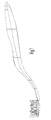
- a core 1 of metal material is first manufactured, for example such as the one clearly shown in fig. 1A-1D .
- the metal core 1 has an elongated, slim profile - especially in the neck portion C, i.e. between the area G of engagement with the head and the handle area I - which is rather thin.
- metal core 1 has an open-V, transversal profile, at least on the entire handle portion and on part of neck C. This profile allows to obtain a good inertia modulus which makes the entire core more rigid to bending, despite reduced material thickness.
- the thickness preferably lies in the range 0.2 mm to 3 mm, preferably below 1.5 mm and even more preferably below 1 mm. As a matter of fact, it has been detected that a larger thickness would cause excessive thermal inertia which, depending on the material, would end up making the cooling times and the shrinkage ratios incompatible with those of the plastic material in which the core is intended to be embedded.
- a preferred metal material for core 1 is a zinc-and-aluminium based alloy (zama), but it is not ruled out that also other metals may be equally suitable, such as aluminium, stainless steel, copper alloys and so on.
- An injectable metal alloy, such as a zama alloy, is preferable, which allows to obtain a core having a shape best suited to follow the profile of a toothbrush.
- the metal core may be obtained in any case both by microfusion, and by shearing and bending, by MIM techniques, or other.
- the head portion G of core 1 intended for the coupling with a bristle head, is "racket-shaped".
- the head portion G widens transversally with respect to the neck portion C and forks out into three prongs G 1 , G 2 e G, which join again at the vertex, between which apertures A 1 and A 2 are defined.
- This configuration makes the subsequent coupling with a bristle head particularly effective, as will be set forth in the following.
- engaging means may simply be provided, intended to remain uncovered at the end of the manufacturing process to then be joined, also by the user himself, to an interchangeable head having a matching shape.
- a head may be manufactured by the most preferred technology for the specific tuft topography which it is intended to offer.
- the head consists, in a manner known per se, of a support component 20 provided with a plurality of through-holes 21 wherein bristle tufts 23 are provided to be inserted.
- Component 20, being part of the toothbrush itself, is preferably made of a material consistent with that of the toothbrush, for example plastic material such as polypropylene.
- Bristle tufts 23 are anchored to support component 20 by the anchor-free technology.
- the individual tufts 23 are hence inserted into holes 21 by means of suitable tufting equipment (not shown) and then molten at one base end 23a adjacent to the back side 20a (the lower one in fig. 8 ) of support component 20.
- the localised melting of ends 23a obtained by heat supply or by ultrasounds, causes a joining of the filaments with one another and creates an enlarged head which prevents the withdrawal of the tufts from holes 21 towards the outer side (the top one in fig. 8 ) of component 20.
- the filaments of tufts 23 are typically made of nylon, which melts at a different temperature from that of plate 20.
- the invention after having assembled the tufts with support 20, it is provided to define/apply a thin protection membrane or film 30 adhering to heads 23a of the tufts, as shown in fig. 10 .
- Film 30 has such an extension area as to substantially cover all molten heads 23a of tufts 23 or, at least, those in the proximity of the injection point(s) into the mould intended to produce the back portion of the head.
- the film has a profile equivalent to that of support 20, but slightly smaller, so as to cover all the heads 23a of the tufts, except part of the peripheral ones.
- This configuration is particularly advantageous because it allows to substantially cover all the tuft heads, but leaves a free peripheral rim which ensures an effective bonding of the subsequent injected material to the peripheral portion of support 20.
- Film 30 must be of a material which does not melt immediately upon contact with the molten plastic material which is subsequently injected to complete the back portion of the head. This allows to preserve its shielding effectiveness - according to what is set forth below - at least for the entire initial step of the injection, during which the injection pressure is higher.
- protection film 30 has an adhesive side, for example it is an adhesive paper label.
- the adhesive side of the film is placed in contact with tuft heads 23a and allows to apply and keep easily in position the protection film or membrane 30 during the industrial process for the handling and moulding of the toothbrush.
- the protection film can also be made of other materials, such as also metal alloys (for example aluminium) or the very material of which the subsequently injected toothbrush head portion is made.
- metal alloys for example aluminium
- membrane or film 30 will melt together with the material supplied during the second high-pressure injection of plastic material (the one used to obtain the remaining toothbrush portion), but with a sufficient delay to perform in any case its protective function.
- the thickness of membrane 30 depends on the material it is made of, it being proportionally larger in the case of a membrane of a plastic material partly melting at the injection temperatures/pressures. For example, it has been detected that an adhesive paper label can perform its task very well with a thickness of 50-400 ⁇ m.
- the thickness is in any case preferably such that membrane 30 maintains a certain flexibility, so as to better adapt to the irregular surface 20a of support 20, scattered with the flattened heads 23a of the tufts.
- a head insert T according to a preferred embodiment is shown, once the moulding and hardening (cooling) step of the back portion and the corresponding ejection from the mould has been completed.
- the bristle head displays a back surface provided with a matching footprint. That is, the back of the head has recesses and reliefs in correspondence of prongs G 1 -G 3 and apertures A 1 -A 3 , respectively, of the head portion of core 1. This makes the coupling between the core and the head on the adhesion plane thereof potentially stable, so as to prevent undesired relative movements during the moulding step.
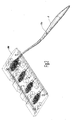
- a series of bristle heads T are formed and completed on a metal mask M, by means of which the heads can be handled and transferred along the production line.
- Each mask M may comprise, as shown in the drawings, four footprints for an equal number of heads ( fig. 2 ).
- the bristle masks then arrive at an assembling/moulding station in correspondence of which they are housed - for example after having been methodically taken from a storage by a gripping hand with vacuum suction - and locked in a corresponding seat of a lower half-mould S 1 of the mould, wherein an equal number of footprints P 1 -P 4 is obtained, which define a part of the mould cavity for a semi-finished toothbrush.
- Lower half-mould S 1 preferably comprises a footprint number multiple of the number of footprints existing on masks M and is hence arranged for housing a certain number of masks, for example four aligned masks next to one another.
- a rotary turntable (not shown) there are preferably mounted two half-moulds S 1 , in opposition one to the other, which can thereby be alternatively brought below a moulding head, where a coupling occurs with an upper half-mould S 2 and the injection of plastic material of a first component.
- Moulding turntable systems of the prior art, are described for example in EP 893 225 and EP 836 923 in the name of G.B. Boucherie NV.
- each of footprints P 1 -P 4 intended to house a metal core 1, as clearly visible in fig. 3 is provided with two support platforms Q 1 -Q 4 and R 1 -R 4 apt to support and retain core 1 in a central position with respect to the toothbrush body.
- the two support platforms Q and R rise from the bottom of footprint P and define a support or contact surface which lies in the proximity of a central line of the mould cavity, i.e. of the toothbrush.
- the two platforms are arranged one (R) in the proximity of the handle end of the toothbrush, while the other one (Q) is in the proximity of the CG area of core 1, i.e. in the proximity of the connection between handle portion I and neck portion C.
- the surfaces of the two platforms Q and R intended to come in contact with core 1 are preferably shaped so as to match the possibly-curved, corresponding surface conformation of core 1.
- CG platform Q displays a minimal length and is rather elongated in the longitudinal direction of the footprint.
- the upstream edge Q' (leading edge), with respect to the injection point of the plastic material (Z 1 ), has a rising front with a rounded profile; conversely, the downstream edge Q" (trailing edge) displays a tilted front and, possibly, with a more tapered profile.
- CG support platform Q preferably has a pin N intended to engage with a corresponding hole 1a of metal core 1.
- the pin projects from the respective platform according to a direction favourable to the introduction of hole la during the movement of deposition of core 1 into footprint P.
- This pin N has the twofold task of longitudinally centring core 1 in its moulding footprint P, as well as of providing a valid constraint of the same core, which prevents undesired transversal displacements, especially during the pressure injection of the plastic material into the mould.
- the secure fastening of the core to the inside of the mould cavity is one of the critical points for the success of the finished product.
- the plastic material is normally injected at a high pressure (even up to the order of 700-800 bar) and hence the push imparted to the inner core would risk shifting it from its position established by the design.
- hole 1a maintains an advantageous usefulness also during the subsequent step of moulding the plastic material, as will be highlighted further on.
- An upper half-mould S 2 is furthermore provided to cooperate with lower half-mould S 1 , so as to define a footprint P' which defines, together with lower footprint P, the moulding cavity of the first component.
- upper half-mould S 2 also has a support for retaining metal core 1.
- the upper half-mould has an elongated ribbing L (the half-mould portion resting on core 1 visible in the section of fig. 4 ), intended to come in contact in the cavity of core 1 (i.e. above in the drawing of fig. 4 ) in an area lying between the two lower support platforms Q and R and opposite thereto with respect to the core.
- an effective locking system for core 1 is configured.
- This locking system avoids any undesired movement of metal core 1 in the mould, especially during the injection of the first plastic component, but at the same time it is very little invasive and hence does not negatively affect the solidity of the moulded plastic material nor its final aesthetic result.
- metal core 1 is preferably suited to be fully covered by the plastic material of the first component, except for the areas resting on platforms Q and R and ribbing L.
- the entire peripheral edge of the metal core is covered with the first structural plastic component, for example polypropylene.
- first structural plastic component for example polypropylene.
- the support areas (which can be better defined as areas of contact with the metal core) of platforms Q and R and of ribbing L must be sufficiently narrow so as not to affect the peripheral edge area of the core.
- the point of injection of the first component preferably lies in the proximity of the rear end of the handle (Z 1 end of channel Z in fig. 4 ).
- the injection since it occurs at the end of the mould cavity, is preferably pressure-controlled, in order to suitably adjust the pressure in the mould and the progress of the injection front. Injection may occur, for example, over 2-3 seconds with three-four different subsequent pressure events.
- core 1 is well-centred along a central line within the mould cavity causes also the cavity volumes on both sides of the core to be substantially balanced: this avoids pressure peaks on either side of core 1, which might otherwise bend the core during injection and move it into an undesired position.
- Another point of preventive low-pressure injection may be provided in the proximity of the head, should membrane 30 be provided directly in the mould.
- the plastic material injected at high pressure closes and completes the back of the head.
- the plastic material supplied during injection ends up bonding with at least part of the inner side 20a of support 20, in particular along the periphery thereof, being made of identical or substantially compatible and related material.
- membrane 30 comprises no contraindication.
- the materials for example a clear plastic material (at least once cooled in the condition of use) for the toothbrush head and a variously coloured or patterned support for film 30 - it is possible to obtain appealing colour and aesthetic effects.
- the rotation of the turntable brings the lower half-mould in the initial position, wherefrom the semi-finished products are taken, so as to free half-mould S 1 which is ready again for a subsequent loading cycle.
- the semi-finished products are as illustrated in figs. 5A-5E .
- the semi-finished products are then sent to a second mould (possibly arranged on the same turntable or in a second moulding station) where a second finishing plastic component is applied, for example an elastomeric material.
- a second mould possibly arranged on the same turntable or in a second moulding station
- a second finishing plastic component is applied, for example an elastomeric material.
- the semi-finished product is therefore introduced, in a manner known per se, into a new mould into which the second component is injected which, in addition to aesthetically finishing the toothbrush, fills the recesses 2a-2c left by the support and locking system of metal core 1.
- the finishing and filling plastic material injected by one of the two parts of hole 1a, for example into the recess 2b left by ribbing L, can overflow also onto the other side.
- the provision of hole 1a - in addition to the retaining function set forth above - hence allows both to inject plastic material on one side only of the two parts, and to obtain a resistant anchoring of the two opposite masses of elastomeric material to the toothbrush body, because they join through the hole.
- the toothbrush is complete ( fig. 7 ) and may be sent to a quality assurance line and then for packaging.
- the teachings according to the invention allow to define a moulding process and the corresponding mould, particularly suited for obtaining a toothbrush with a slim metal core.
- the process allows to perfectly embed the metal core into the plastic body of the toothbrush (so as not to leave it exposed to external agents), securely fastening also the bristle head component.
- the perfect retaining of the core in the mould despite its slimness, further allows to obtain a product of excellent quality and finishing.
- a different coupling element may be provided which holds the metal core at least in its transversal direction inside its footprint P in mould 1.
- the method of the invention is well-suited also to manufacture an entire toothbrush, wherein the head portion is integral with the handle and is subsequently bristled with a conventional anchor technique.
- the resistant inner core is not ruled out for the resistant inner core to be made of non-metal materials, possibly having a high elastic modulus, obtaining a product with equivalent features.
Landscapes
- Engineering & Computer Science (AREA)
- Manufacturing & Machinery (AREA)
- Mechanical Engineering (AREA)
- Brushes (AREA)
- Injection Moulding Of Plastics Or The Like (AREA)
Priority Applications (1)
| Application Number | Priority Date | Filing Date | Title |
|---|---|---|---|
| EP10190377.1A EP2295220B1 (fr) | 2008-01-07 | 2009-01-07 | Procédé de fabrication d'une brosse à dents et sa tête |
Applications Claiming Priority (2)
| Application Number | Priority Date | Filing Date | Title |
|---|---|---|---|
| ITMI20080014 ITMI20080014A1 (it) | 2008-01-07 | 2008-01-07 | Metodo di fabbricazione di uno spazzolino con tecnologia in-molding e spazzolino ottenuto con tale metodo. |
| ITMI20080447 ITMI20080447A1 (it) | 2008-03-17 | 2008-03-17 | Metodo di fabbricazione di uno spazzolino con anima metallica e stampo per tale metodo. |
Related Child Applications (3)
| Application Number | Title | Priority Date | Filing Date |
|---|---|---|---|
| EP10190377.1A Division EP2295220B1 (fr) | 2008-01-07 | 2009-01-07 | Procédé de fabrication d'une brosse à dents et sa tête |
| EP10190377.1A Previously-Filed-Application EP2295220B1 (fr) | 2008-01-07 | 2009-01-07 | Procédé de fabrication d'une brosse à dents et sa tête |
| EP10190377.1 Division-Into | 2010-11-08 |
Publications (4)
| Publication Number | Publication Date |
|---|---|
| EP2077181A2 true EP2077181A2 (fr) | 2009-07-08 |
| EP2077181A3 EP2077181A3 (fr) | 2009-07-22 |
| EP2077181B1 EP2077181B1 (fr) | 2010-12-29 |
| EP2077181B9 EP2077181B9 (fr) | 2011-10-05 |
Family
ID=40524815
Family Applications (2)
| Application Number | Title | Priority Date | Filing Date |
|---|---|---|---|
| EP09150140A Not-in-force EP2077181B9 (fr) | 2008-01-07 | 2009-01-07 | Procédé de fabrication d'une brosse à dents, brosse à dents obtenue avec ce procédé et moule pour un tel procédé |
| EP10190377.1A Not-in-force EP2295220B1 (fr) | 2008-01-07 | 2009-01-07 | Procédé de fabrication d'une brosse à dents et sa tête |
Family Applications After (1)
| Application Number | Title | Priority Date | Filing Date |
|---|---|---|---|
| EP10190377.1A Not-in-force EP2295220B1 (fr) | 2008-01-07 | 2009-01-07 | Procédé de fabrication d'une brosse à dents et sa tête |
Country Status (5)
| Country | Link |
|---|---|
| US (2) | US8376470B2 (fr) |
| EP (2) | EP2077181B9 (fr) |
| AT (1) | ATE493256T1 (fr) |
| DE (1) | DE602009000468D1 (fr) |
| ES (1) | ES2495345T3 (fr) |
Cited By (2)
| Publication number | Priority date | Publication date | Assignee | Title |
|---|---|---|---|---|
| EP2807948A1 (fr) * | 2013-05-29 | 2014-12-03 | The Gillette Company | Procédé pour produire une brosse à dents et brosse à dents ainsi produite |
| EP2587592B1 (fr) * | 2011-10-24 | 2016-03-30 | PHOENIX CONTACT GmbH & Co. KG | Raccordement de câble multipolaire et procédé de fabrication d'un raccordement de câble multipolaire |
Families Citing this family (9)
| Publication number | Priority date | Publication date | Assignee | Title |
|---|---|---|---|---|
| CN101674750A (zh) * | 2007-04-12 | 2010-03-17 | 荷兰联合利华有限公司 | 具有金属骨架和围绕其铸造的塑料主体的牙刷 |
| JP5759453B2 (ja) * | 2009-05-27 | 2015-08-05 | ビック・バイオレクス・エス・エー | ラベルを統合して成型された製品、およびそのような成型品を具備したレイザハンドル |
| USD679508S1 (en) * | 2010-03-12 | 2013-04-09 | United Element, LLC | Container with set of toothbrush handles and removably connectable heads |
| CN103607927B (zh) * | 2011-06-15 | 2015-12-23 | 吉列公司 | 头部设有两个柔性翼部的口腔护理器械 |
| US9717324B2 (en) * | 2013-05-29 | 2017-08-01 | The Gillette Company Llc | Method for producing a toothbrush and toothbrush produced thereby |
| CN208096391U (zh) * | 2017-11-13 | 2018-11-16 | Jc雅博生物科技有限公司 | 一种牙刷及其制造模具 |
| JP7652528B2 (ja) | 2018-12-28 | 2025-03-27 | 小林製薬株式会社 | 歯間清掃具 |
| JP2020103851A (ja) | 2018-12-28 | 2020-07-09 | 小林製薬株式会社 | 歯間清掃具 |
| JP7417353B2 (ja) * | 2018-12-28 | 2024-01-18 | 小林製薬株式会社 | 歯間清掃具の製造方法 |
Citations (4)
| Publication number | Priority date | Publication date | Assignee | Title |
|---|---|---|---|---|
| GB2050156A (en) | 1979-04-27 | 1981-01-07 | Pakarnseree S | Toothbrush |
| EP0567672A1 (fr) | 1992-04-28 | 1993-11-03 | G.B. Boucherie, N.V. | Procédé pour fabriquer des brosses à dents |
| EP0836923A1 (fr) | 1996-10-21 | 1998-04-22 | Bart Gerard Boucherie | Procédé et dispositif pour fabriquer des corps de brosse pour brosses à dents |
| EP0893225A2 (fr) | 1994-04-19 | 1999-01-27 | G.B. Boucherie N.V. | Machine pour le moulage par injection de brosses à dents |
Family Cites Families (13)
| Publication number | Priority date | Publication date | Assignee | Title |
|---|---|---|---|---|
| FR2079455A5 (en) * | 1970-02-02 | 1971-11-12 | Lardenois Robert | Plastic brush handles - moulded with an insert of decorated foil |
| US4691405A (en) * | 1985-07-29 | 1987-09-08 | Reed Joseph C | Toothbrush having adjustable bristle-mounted tabs |
| FR2727049B1 (fr) * | 1994-11-18 | 1997-01-24 | Plastic Omnium Cie | Procede de realisation d'un temoin d'usure de garniture de friction surmoule |
| SI0960010T1 (en) * | 1997-02-14 | 2003-12-31 | Smithkline Beecham Consumer Healthcare Gmbh | Injection moulding process and apparatus for making articles from two components |
| JPH11254475A (ja) * | 1998-03-12 | 1999-09-21 | Kao Corp | プラスチック成形品の製造方法 |
| GB0014495D0 (en) * | 2000-06-15 | 2000-08-09 | Smithkline Beecham Gmbh & Co | Process |
| JP2003025376A (ja) * | 2001-07-12 | 2003-01-29 | Lion Corp | 歯ブラシハンドルの製造方法 |
| JP3976648B2 (ja) * | 2001-08-24 | 2007-09-19 | 花王株式会社 | 歯ブラシの製造方法 |
| US20030131433A1 (en) * | 2002-01-15 | 2003-07-17 | Pavone Bernadino J. | Orthodontic toothbrush |
| DE10303548B4 (de) * | 2003-01-29 | 2016-10-20 | M + C Schiffer Gmbh | Bürste und Verfahren zu deren Herstellung |
| GB0317539D0 (en) * | 2003-07-25 | 2003-08-27 | Glaxosmithkline Consumer Healt | Toothbrush |
| CA2596685C (fr) * | 2005-02-02 | 2014-04-01 | Sunstar Inc. | Brosse a dents |
| US8308246B2 (en) * | 2010-03-19 | 2012-11-13 | Chung Tae Sang | Method for manufacturing toothbrush and toothbrush manufactured by the method |
-
2009
- 2009-01-06 US US12/349,092 patent/US8376470B2/en not_active Expired - Fee Related
- 2009-01-07 ES ES10190377.1T patent/ES2495345T3/es active Active
- 2009-01-07 EP EP09150140A patent/EP2077181B9/fr not_active Not-in-force
- 2009-01-07 AT AT09150140T patent/ATE493256T1/de active
- 2009-01-07 DE DE602009000468T patent/DE602009000468D1/de active Active
- 2009-01-07 EP EP10190377.1A patent/EP2295220B1/fr not_active Not-in-force
-
2013
- 2013-01-10 US US13/738,440 patent/US8690263B2/en active Active
Patent Citations (4)
| Publication number | Priority date | Publication date | Assignee | Title |
|---|---|---|---|---|
| GB2050156A (en) | 1979-04-27 | 1981-01-07 | Pakarnseree S | Toothbrush |
| EP0567672A1 (fr) | 1992-04-28 | 1993-11-03 | G.B. Boucherie, N.V. | Procédé pour fabriquer des brosses à dents |
| EP0893225A2 (fr) | 1994-04-19 | 1999-01-27 | G.B. Boucherie N.V. | Machine pour le moulage par injection de brosses à dents |
| EP0836923A1 (fr) | 1996-10-21 | 1998-04-22 | Bart Gerard Boucherie | Procédé et dispositif pour fabriquer des corps de brosse pour brosses à dents |
Cited By (4)
| Publication number | Priority date | Publication date | Assignee | Title |
|---|---|---|---|---|
| EP2587592B1 (fr) * | 2011-10-24 | 2016-03-30 | PHOENIX CONTACT GmbH & Co. KG | Raccordement de câble multipolaire et procédé de fabrication d'un raccordement de câble multipolaire |
| US9559437B2 (en) | 2011-10-24 | 2017-01-31 | Phoenix Contact Gmbh & Co. Kg | Multi-pole cable connection and method for producing a multi-pole cable connection |
| EP2807948A1 (fr) * | 2013-05-29 | 2014-12-03 | The Gillette Company | Procédé pour produire une brosse à dents et brosse à dents ainsi produite |
| WO2014193621A1 (fr) * | 2013-05-29 | 2014-12-04 | The Gillette Company | Procédé pour produire une brosse à dents et brosse à dents produite par ce dernier |
Also Published As
| Publication number | Publication date |
|---|---|
| EP2295220B1 (fr) | 2014-06-04 |
| EP2295220A1 (fr) | 2011-03-16 |
| DE602009000468D1 (de) | 2011-02-10 |
| EP2077181B1 (fr) | 2010-12-29 |
| US20130147254A1 (en) | 2013-06-13 |
| ES2495345T3 (es) | 2014-09-17 |
| EP2077181A3 (fr) | 2009-07-22 |
| ATE493256T1 (de) | 2011-01-15 |
| US8376470B2 (en) | 2013-02-19 |
| EP2077181B9 (fr) | 2011-10-05 |
| US20090193603A1 (en) | 2009-08-06 |
| US8690263B2 (en) | 2014-04-08 |
Similar Documents
| Publication | Publication Date | Title |
|---|---|---|
| EP2077181B1 (fr) | Procédé de fabrication d'une brosse à dents, brosse à dents obtenue avec ce procédé et moule pour un tel procédé | |
| EP1289729B1 (fr) | Moulage par injection d'articles composites et brosses a dents realisees selon ce procede | |
| US6749788B1 (en) | Method and apparatus for making a shaving razor handle | |
| EP1864588B1 (fr) | Brosse à dents et procédé destiné à sa fabrication | |
| CN101111170B (zh) | 牙刷 | |
| CN102159115B (zh) | 用于制造刷子尤其是牙刷的方法 | |
| EP1312281A1 (fr) | Procede et dispositif de fabrication d'une brosse | |
| CN103507201B (zh) | 制造一体式多组分注塑成形的刷子的方法 | |
| TW201731466A (zh) | 齒間清掃具 | |
| US6352313B1 (en) | Brush tufting | |
| EP1225821B1 (fr) | Les poils d'une brosse | |
| KR20120056311A (ko) | 칫솔 제조 방법 및 이 방법으로 제조된 칫솔 | |
| JP3976648B2 (ja) | 歯ブラシの製造方法 | |
| JP4778166B2 (ja) | ブラシ及びブラシの製造方法 | |
| CN104379023B (zh) | 用于清洁元件的载体和用于制备此类可用于制备牙刷头部的载体的方法 | |
| JP4004305B2 (ja) | ブラシの製造方法 | |
| DE10217527A1 (de) | Verfahren zum Herstellen von Bürsten sowie danach hergestellte Bürste | |
| KR100547905B1 (ko) | 인서트 합성수지 삽 및 그 제조방법 | |
| JP3976647B2 (ja) | 歯ブラシの製造方法及び歯ブラシ | |
| JPH0956479A (ja) | ブラシおよびその製造方法 | |
| JP2003235645A (ja) | ブラシの製造方法 | |
| ES2355662T3 (es) | Método para fabricar un cepillo de dientes, cepillo de dientes obtenido con dicho método y molde para ese método. | |
| ITMI20080447A1 (it) | Metodo di fabbricazione di uno spazzolino con anima metallica e stampo per tale metodo. | |
| JP2003235647A (ja) | ブラシの製造方法 | |
| WO2019158370A1 (fr) | Agencements de tête de brosse et procédé de fabrication |
Legal Events
| Date | Code | Title | Description |
|---|---|---|---|
| PUAI | Public reference made under article 153(3) epc to a published international application that has entered the european phase |
Free format text: ORIGINAL CODE: 0009012 |
|
| PUAL | Search report despatched |
Free format text: ORIGINAL CODE: 0009013 |
|
| AK | Designated contracting states |
Kind code of ref document: A2 Designated state(s): AT BE BG CH CY CZ DE DK EE ES FI FR GB GR HR HU IE IS IT LI LT LU LV MC MK MT NL NO PL PT RO SE SI SK TR |
|
| AX | Request for extension of the european patent |
Extension state: AL BA RS |
|
| AK | Designated contracting states |
Kind code of ref document: A3 Designated state(s): AT BE BG CH CY CZ DE DK EE ES FI FR GB GR HR HU IE IS IT LI LT LU LV MC MK MT NL NO PL PT RO SE SI SK TR |
|
| AX | Request for extension of the european patent |
Extension state: AL BA RS |
|
| 17P | Request for examination filed |
Effective date: 20100122 |
|
| 17Q | First examination report despatched |
Effective date: 20100215 |
|
| AKX | Designation fees paid |
Designated state(s): AT BE BG CH CY CZ DE DK EE ES FI FR GB GR HR HU IE IS IT LI LT LU LV MC MK MT NL NO PL PT RO SE SI SK TR |
|
| GRAP | Despatch of communication of intention to grant a patent |
Free format text: ORIGINAL CODE: EPIDOSNIGR1 |
|
| RTI1 | Title (correction) |
Free format text: METHOD FOR MANUFACTURING A TOOTHBRUSH, TOOTHBRUSH OBTAINED WITH SAID METHOD AND MOULD FOR SUCH METHOD |
|
| GRAS | Grant fee paid |
Free format text: ORIGINAL CODE: EPIDOSNIGR3 |
|
| GRAA | (expected) grant |
Free format text: ORIGINAL CODE: 0009210 |
|
| AK | Designated contracting states |
Kind code of ref document: B1 Designated state(s): AT BE BG CH CY CZ DE DK EE ES FI FR GB GR HR HU IE IS IT LI LT LU LV MC MK MT NL NO PL PT RO SE SI SK TR |
|
| REG | Reference to a national code |
Ref country code: GB Ref legal event code: FG4D |
|
| REG | Reference to a national code |
Ref country code: CH Ref legal event code: EP |
|
| REG | Reference to a national code |
Ref country code: IE Ref legal event code: FG4D |
|
| REF | Corresponds to: |
Ref document number: 602009000468 Country of ref document: DE Date of ref document: 20110210 Kind code of ref document: P |
|
| REG | Reference to a national code |
Ref country code: DE Ref legal event code: R096 Ref document number: 602009000468 Country of ref document: DE Effective date: 20110210 |
|
| REG | Reference to a national code |
Ref country code: CH Ref legal event code: NV Representative=s name: OK PAT AG PATENTE MARKEN LIZENZEN |
|
| REG | Reference to a national code |
Ref country code: NL Ref legal event code: T3 |
|
| RAP2 | Party data changed (patent owner data changed or rights of a patent transferred) |
Owner name: PONZINI S.P.A. |
|
| REG | Reference to a national code |
Ref country code: ES Ref legal event code: FG2A Ref document number: 2355662 Country of ref document: ES Kind code of ref document: T3 Effective date: 20110329 |
|
| PG25 | Lapsed in a contracting state [announced via postgrant information from national office to epo] |
Ref country code: LT Free format text: LAPSE BECAUSE OF FAILURE TO SUBMIT A TRANSLATION OF THE DESCRIPTION OR TO PAY THE FEE WITHIN THE PRESCRIBED TIME-LIMIT Effective date: 20101229 |
|
| LTIE | Lt: invalidation of european patent or patent extension |
Effective date: 20101229 |
|
| PG25 | Lapsed in a contracting state [announced via postgrant information from national office to epo] |
Ref country code: BG Free format text: LAPSE BECAUSE OF FAILURE TO SUBMIT A TRANSLATION OF THE DESCRIPTION OR TO PAY THE FEE WITHIN THE PRESCRIBED TIME-LIMIT Effective date: 20110329 Ref country code: FI Free format text: LAPSE BECAUSE OF FAILURE TO SUBMIT A TRANSLATION OF THE DESCRIPTION OR TO PAY THE FEE WITHIN THE PRESCRIBED TIME-LIMIT Effective date: 20101229 Ref country code: SE Free format text: LAPSE BECAUSE OF FAILURE TO SUBMIT A TRANSLATION OF THE DESCRIPTION OR TO PAY THE FEE WITHIN THE PRESCRIBED TIME-LIMIT Effective date: 20101229 Ref country code: HR Free format text: LAPSE BECAUSE OF FAILURE TO SUBMIT A TRANSLATION OF THE DESCRIPTION OR TO PAY THE FEE WITHIN THE PRESCRIBED TIME-LIMIT Effective date: 20101229 Ref country code: CY Free format text: LAPSE BECAUSE OF FAILURE TO SUBMIT A TRANSLATION OF THE DESCRIPTION OR TO PAY THE FEE WITHIN THE PRESCRIBED TIME-LIMIT Effective date: 20101229 Ref country code: SI Free format text: LAPSE BECAUSE OF FAILURE TO SUBMIT A TRANSLATION OF THE DESCRIPTION OR TO PAY THE FEE WITHIN THE PRESCRIBED TIME-LIMIT Effective date: 20101229 Ref country code: LV Free format text: LAPSE BECAUSE OF FAILURE TO SUBMIT A TRANSLATION OF THE DESCRIPTION OR TO PAY THE FEE WITHIN THE PRESCRIBED TIME-LIMIT Effective date: 20101229 |
|
| PG25 | Lapsed in a contracting state [announced via postgrant information from national office to epo] |
Ref country code: GR Free format text: LAPSE BECAUSE OF FAILURE TO SUBMIT A TRANSLATION OF THE DESCRIPTION OR TO PAY THE FEE WITHIN THE PRESCRIBED TIME-LIMIT Effective date: 20110330 Ref country code: IS Free format text: LAPSE BECAUSE OF FAILURE TO SUBMIT A TRANSLATION OF THE DESCRIPTION OR TO PAY THE FEE WITHIN THE PRESCRIBED TIME-LIMIT Effective date: 20110429 Ref country code: NO Free format text: LAPSE BECAUSE OF FAILURE TO SUBMIT A TRANSLATION OF THE DESCRIPTION OR TO PAY THE FEE WITHIN THE PRESCRIBED TIME-LIMIT Effective date: 20110329 Ref country code: PT Free format text: LAPSE BECAUSE OF FAILURE TO SUBMIT A TRANSLATION OF THE DESCRIPTION OR TO PAY THE FEE WITHIN THE PRESCRIBED TIME-LIMIT Effective date: 20110429 Ref country code: CZ Free format text: LAPSE BECAUSE OF FAILURE TO SUBMIT A TRANSLATION OF THE DESCRIPTION OR TO PAY THE FEE WITHIN THE PRESCRIBED TIME-LIMIT Effective date: 20101229 Ref country code: EE Free format text: LAPSE BECAUSE OF FAILURE TO SUBMIT A TRANSLATION OF THE DESCRIPTION OR TO PAY THE FEE WITHIN THE PRESCRIBED TIME-LIMIT Effective date: 20101229 |
|
| PG25 | Lapsed in a contracting state [announced via postgrant information from national office to epo] |
Ref country code: MC Free format text: LAPSE BECAUSE OF NON-PAYMENT OF DUE FEES Effective date: 20110131 Ref country code: PL Free format text: LAPSE BECAUSE OF FAILURE TO SUBMIT A TRANSLATION OF THE DESCRIPTION OR TO PAY THE FEE WITHIN THE PRESCRIBED TIME-LIMIT Effective date: 20101229 Ref country code: SK Free format text: LAPSE BECAUSE OF FAILURE TO SUBMIT A TRANSLATION OF THE DESCRIPTION OR TO PAY THE FEE WITHIN THE PRESCRIBED TIME-LIMIT Effective date: 20101229 Ref country code: RO Free format text: LAPSE BECAUSE OF FAILURE TO SUBMIT A TRANSLATION OF THE DESCRIPTION OR TO PAY THE FEE WITHIN THE PRESCRIBED TIME-LIMIT Effective date: 20101229 |
|
| REG | Reference to a national code |
Ref country code: IE Ref legal event code: MM4A |
|
| PG25 | Lapsed in a contracting state [announced via postgrant information from national office to epo] |
Ref country code: DK Free format text: LAPSE BECAUSE OF FAILURE TO SUBMIT A TRANSLATION OF THE DESCRIPTION OR TO PAY THE FEE WITHIN THE PRESCRIBED TIME-LIMIT Effective date: 20101229 |
|
| PLBE | No opposition filed within time limit |
Free format text: ORIGINAL CODE: 0009261 |
|
| STAA | Information on the status of an ep patent application or granted ep patent |
Free format text: STATUS: NO OPPOSITION FILED WITHIN TIME LIMIT |
|
| 26N | No opposition filed |
Effective date: 20110930 |
|
| PG25 | Lapsed in a contracting state [announced via postgrant information from national office to epo] |
Ref country code: MT Free format text: LAPSE BECAUSE OF FAILURE TO SUBMIT A TRANSLATION OF THE DESCRIPTION OR TO PAY THE FEE WITHIN THE PRESCRIBED TIME-LIMIT Effective date: 20101229 |
|
| REG | Reference to a national code |
Ref country code: DE Ref legal event code: R097 Ref document number: 602009000468 Country of ref document: DE Effective date: 20110930 |
|
| PG25 | Lapsed in a contracting state [announced via postgrant information from national office to epo] |
Ref country code: IE Free format text: LAPSE BECAUSE OF NON-PAYMENT OF DUE FEES Effective date: 20110107 |
|
| PG25 | Lapsed in a contracting state [announced via postgrant information from national office to epo] |
Ref country code: MK Free format text: LAPSE BECAUSE OF FAILURE TO SUBMIT A TRANSLATION OF THE DESCRIPTION OR TO PAY THE FEE WITHIN THE PRESCRIBED TIME-LIMIT Effective date: 20101229 |
|
| PG25 | Lapsed in a contracting state [announced via postgrant information from national office to epo] |
Ref country code: LU Free format text: LAPSE BECAUSE OF NON-PAYMENT OF DUE FEES Effective date: 20110107 |
|
| PG25 | Lapsed in a contracting state [announced via postgrant information from national office to epo] |
Ref country code: TR Free format text: LAPSE BECAUSE OF FAILURE TO SUBMIT A TRANSLATION OF THE DESCRIPTION OR TO PAY THE FEE WITHIN THE PRESCRIBED TIME-LIMIT Effective date: 20101229 |
|
| PG25 | Lapsed in a contracting state [announced via postgrant information from national office to epo] |
Ref country code: HU Free format text: LAPSE BECAUSE OF FAILURE TO SUBMIT A TRANSLATION OF THE DESCRIPTION OR TO PAY THE FEE WITHIN THE PRESCRIBED TIME-LIMIT Effective date: 20101229 |
|
| REG | Reference to a national code |
Ref country code: FR Ref legal event code: PLFP Year of fee payment: 8 |
|
| REG | Reference to a national code |
Ref country code: FR Ref legal event code: PLFP Year of fee payment: 9 |
|
| REG | Reference to a national code |
Ref country code: FR Ref legal event code: PLFP Year of fee payment: 10 |
|
| PGFP | Annual fee paid to national office [announced via postgrant information from national office to epo] |
Ref country code: CH Payment date: 20181218 Year of fee payment: 11 Ref country code: FR Payment date: 20181218 Year of fee payment: 11 Ref country code: GB Payment date: 20181218 Year of fee payment: 11 |
|
| PGFP | Annual fee paid to national office [announced via postgrant information from national office to epo] |
Ref country code: NL Payment date: 20190121 Year of fee payment: 11 Ref country code: IT Payment date: 20190107 Year of fee payment: 11 Ref country code: DE Payment date: 20181218 Year of fee payment: 11 Ref country code: ES Payment date: 20190206 Year of fee payment: 11 |
|
| PGFP | Annual fee paid to national office [announced via postgrant information from national office to epo] |
Ref country code: AT Payment date: 20190109 Year of fee payment: 11 Ref country code: BE Payment date: 20190131 Year of fee payment: 11 |
|
| REG | Reference to a national code |
Ref country code: DE Ref legal event code: R119 Ref document number: 602009000468 Country of ref document: DE |
|
| REG | Reference to a national code |
Ref country code: CH Ref legal event code: PL |
|
| REG | Reference to a national code |
Ref country code: NL Ref legal event code: MM Effective date: 20200201 |
|
| REG | Reference to a national code |
Ref country code: AT Ref legal event code: MM01 Ref document number: 493256 Country of ref document: AT Kind code of ref document: T Effective date: 20200107 |
|
| GBPC | Gb: european patent ceased through non-payment of renewal fee |
Effective date: 20200107 |
|
| REG | Reference to a national code |
Ref country code: BE Ref legal event code: MM Effective date: 20200131 |
|
| PG25 | Lapsed in a contracting state [announced via postgrant information from national office to epo] |
Ref country code: DE Free format text: LAPSE BECAUSE OF NON-PAYMENT OF DUE FEES Effective date: 20200801 Ref country code: NL Free format text: LAPSE BECAUSE OF NON-PAYMENT OF DUE FEES Effective date: 20200201 Ref country code: FR Free format text: LAPSE BECAUSE OF NON-PAYMENT OF DUE FEES Effective date: 20200131 Ref country code: GB Free format text: LAPSE BECAUSE OF NON-PAYMENT OF DUE FEES Effective date: 20200107 |
|
| PG25 | Lapsed in a contracting state [announced via postgrant information from national office to epo] |
Ref country code: AT Free format text: LAPSE BECAUSE OF NON-PAYMENT OF DUE FEES Effective date: 20200107 Ref country code: LI Free format text: LAPSE BECAUSE OF NON-PAYMENT OF DUE FEES Effective date: 20200131 Ref country code: CH Free format text: LAPSE BECAUSE OF NON-PAYMENT OF DUE FEES Effective date: 20200131 Ref country code: BE Free format text: LAPSE BECAUSE OF NON-PAYMENT OF DUE FEES Effective date: 20200131 |
|
| PG25 | Lapsed in a contracting state [announced via postgrant information from national office to epo] |
Ref country code: IT Free format text: LAPSE BECAUSE OF NON-PAYMENT OF DUE FEES Effective date: 20200107 |
|
| REG | Reference to a national code |
Ref country code: ES Ref legal event code: FD2A Effective date: 20210602 |
|
| PG25 | Lapsed in a contracting state [announced via postgrant information from national office to epo] |
Ref country code: ES Free format text: LAPSE BECAUSE OF NON-PAYMENT OF DUE FEES Effective date: 20200108 |