EP2077227A2 - Tauchfähige Antriebseinheit - Google Patents
Tauchfähige Antriebseinheit Download PDFInfo
- Publication number
- EP2077227A2 EP2077227A2 EP08253884A EP08253884A EP2077227A2 EP 2077227 A2 EP2077227 A2 EP 2077227A2 EP 08253884 A EP08253884 A EP 08253884A EP 08253884 A EP08253884 A EP 08253884A EP 2077227 A2 EP2077227 A2 EP 2077227A2
- Authority
- EP
- European Patent Office
- Prior art keywords
- stiffness
- duct
- propulsor
- vanes
- stators
- Prior art date
- Legal status (The legal status is an assumption and is not a legal conclusion. Google has not performed a legal analysis and makes no representation as to the accuracy of the status listed.)
- Withdrawn
Links
- XLYOFNOQVPJJNP-UHFFFAOYSA-N water Substances O XLYOFNOQVPJJNP-UHFFFAOYSA-N 0.000 claims abstract description 13
- 239000002131 composite material Substances 0.000 claims description 21
- 229910000831 Steel Inorganic materials 0.000 claims description 7
- 239000010959 steel Substances 0.000 claims description 7
- 239000000835 fiber Substances 0.000 claims description 5
- 229920005989 resin Polymers 0.000 claims description 3
- 239000011347 resin Substances 0.000 claims description 3
- 239000002184 metal Substances 0.000 claims description 2
- 229910052751 metal Inorganic materials 0.000 claims description 2
- 239000007769 metal material Substances 0.000 claims description 2
- 239000000463 material Substances 0.000 description 6
- OKTJSMMVPCPJKN-UHFFFAOYSA-N Carbon Chemical compound [C] OKTJSMMVPCPJKN-UHFFFAOYSA-N 0.000 description 4
- 229910052799 carbon Inorganic materials 0.000 description 4
- 239000011521 glass Substances 0.000 description 4
- 238000010586 diagram Methods 0.000 description 3
- 238000011144 upstream manufacturing Methods 0.000 description 3
- 239000004593 Epoxy Substances 0.000 description 2
- 230000008901 benefit Effects 0.000 description 2
- 238000010276 construction Methods 0.000 description 2
- 238000004519 manufacturing process Methods 0.000 description 2
- 230000035939 shock Effects 0.000 description 2
- 229910000906 Bronze Inorganic materials 0.000 description 1
- 229920002430 Fibre-reinforced plastic Polymers 0.000 description 1
- NPXOKRUENSOPAO-UHFFFAOYSA-N Raney nickel Chemical compound [Al].[Ni] NPXOKRUENSOPAO-UHFFFAOYSA-N 0.000 description 1
- 239000000853 adhesive Substances 0.000 description 1
- 230000001070 adhesive effect Effects 0.000 description 1
- 238000003491 array Methods 0.000 description 1
- 239000010974 bronze Substances 0.000 description 1
- 230000007797 corrosion Effects 0.000 description 1
- 238000005260 corrosion Methods 0.000 description 1
- 230000007812 deficiency Effects 0.000 description 1
- 238000012938 design process Methods 0.000 description 1
- 230000001627 detrimental effect Effects 0.000 description 1
- 230000000694 effects Effects 0.000 description 1
- 239000011151 fibre-reinforced plastic Substances 0.000 description 1
- 239000000945 filler Substances 0.000 description 1
- 239000012530 fluid Substances 0.000 description 1
- 238000000034 method Methods 0.000 description 1
- 238000012986 modification Methods 0.000 description 1
- 230000004048 modification Effects 0.000 description 1
- 230000000737 periodic effect Effects 0.000 description 1
- ISWSIDIOOBJBQZ-UHFFFAOYSA-N phenol group Chemical group C1(=CC=CC=C1)O ISWSIDIOOBJBQZ-UHFFFAOYSA-N 0.000 description 1
- 229920000728 polyester Polymers 0.000 description 1
- 229920000642 polymer Polymers 0.000 description 1
- 230000009467 reduction Effects 0.000 description 1
- 230000003068 static effect Effects 0.000 description 1
- 239000003351 stiffener Substances 0.000 description 1
- 229920005992 thermoplastic resin Polymers 0.000 description 1
- 229920001567 vinyl ester resin Polymers 0.000 description 1
Images
Classifications
-
- B—PERFORMING OPERATIONS; TRANSPORTING
- B63—SHIPS OR OTHER WATERBORNE VESSELS; RELATED EQUIPMENT
- B63H—MARINE PROPULSION OR STEERING
- B63H5/00—Arrangements on vessels of propulsion elements directly acting on water
- B63H5/07—Arrangements on vessels of propulsion elements directly acting on water of propellers
- B63H5/14—Arrangements on vessels of propulsion elements directly acting on water of propellers characterised by being mounted in non-rotating ducts or rings, e.g. adjustable for steering purpose
Definitions
- This invention relates to submersible propulsor units.
- Propulsor units are used on ships or boats to drive the vessel through the water.
- One known propulsor is known as a ducted propeller, or pumpjet propulsor.
- This form of propulsor consists of a rotatable rotor mounted within a duct.
- Stator hydrofoils are located forward or aft of the rotor to impart or remove swirl in the flow through the duct depending on whether they are mounted upstream or downstream of the rotor.
- the prior art propulsor units comprise a duct 6 formed either of nickel aluminium bronze (NAB) or a single piece marine grade composite having internal, longitudinally extending stiffeners which limit twisting of the duct. If the duct twists excessively the gap between the tip of the rotor 4 changes giving a greater risk of tip rub.
- NAB nickel aluminium bronze
- the duct is mounted to the hub 10 of the propulsor by a circumferentially extending array of stators 8. These are located upstream of the rotor 4 in the diagram of the prior art, but can be located downstream, or two or more arrays may be provided with a selected number upstream and a selected number downstream of the rotor.
- the stators have the same external form to present the desired flow field to the rotor such that the propulsor either has improved efficiency, or the wake from the propulsor is reduced.
- Each of the stators is formed of NAB that is structurally stiff enough secure the duct and resist twisting caused by the flow of water through the duct.
- NAB provides a satisfactory solution for conventional propulsors; however, the material has a relatively low strength to density ratio, is high in material costs as well as being heavy.
- the stators on conventional propulsors can also vibrate as water flows through the duct to generate periodic frequency responses. These responses, also known as modal responses, can create unwanted noise or vibration throughout the ship or boat structure. Propulsors of this type may be used on large passenger liners and undesirable noise and vibration from the engines can cause discomfort to some passenger. In other applications the modal frequencies may be excited by the rotor at particular shaft rotational speeds. This can give rise to an unwanted noise signature.
- a submersible propulsor unit comprising: a duct defined between a duct hub 10 and a duct wall 6, the duct having a water inlet and a water outlet, a propeller means rotatably mounted within the duct, and an array of stator vanes extending between the duct hub and the duct wall, wherein the array of stator vanes comprises stator vanes having a first stiffness and stator vanes having a second stiffness.
- vanes having a first stiffness and the vanes having a second stiffness present the same external form to the duct.
- vanes having the first stiffness are interleaved with the vanes having the second stiffness.
- vanes having the first stiffness are uniformly interleaved with the vanes having the second stiffness.
- the first stiffness is preferably greater than the second stiffness.
- stator vanes having the first stiffness are formed from metallic material.
- the metal may be NAB or Steel.
- the stiffer vanes have a stiffness of the order 100,000 to 210,000 N/mm ⁇ 2.
- the second stiffness encompasses a range that is of the order 0.1 to 0.8 times that of the higher stiffness vanes.
- An all carbon fibre reinforced resin stator tends to the higher end of the range and as you increase the amount of glass the stiffness is reduced.
- the stator vanes having the second stiffness may be formed from composite.
- the composite is a fibre reinforced resin.
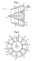
- Figure 1 depicts a cross-section of a marine propulsor commonly known as a ducted propeller or pumpjet propulsor.
- the pumpjet propulsor has similarities with the pumpjet propulsor of the prior art and where possible the diagrams have been given the same reference numerals for the same components as in the prior art.
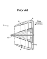
- the propulsor is attached to a submarine though it will be appreciated that with minor modifications it may be attached to surface vessels.
- the propulsor 2 comprises a propeller 4 within a duct 6, which has a static row of stator vanes 8 at the inlet to impart swirl.
- the swirl imparted presents a swirling flow to an array of rotating propeller blades, the swirling flow being cancelled by the rotation of the propeller which allows the wake of the propulsor to be swirl free.
- the duct has a marine composite material sandwich construction formed into a one-piece component.
- the marine composite material offers significant advantages over NAB in terms of improved corrosion resistance, cost and weight.
- the composite materials are structurally less stiff and require longitudinal ribs to achieve the shock strength and manoeuvring rigidity required.
- the improved rigidity provided to the duct prevents twisting and deflection that can reduce rotor tip clearances and increase the risk damage caused by contact between the rotor and the duct.
- the duct is supported by the array of stators 8, which are secured to a centrebody 10.
- the centrebody is structurally mounted to the vessel such that thrust generated by the propeller is transmitted through to the vessel to generate motion of the vessel through the water.
- the centrebody 10 is ring shaped and the stators are mounted in an array extending about the ring and extend radially outwards and are connected at their tips by the surrounding single-piece duct.
- a shaft 12 extends through the hub 10 carrying the stator ring and propeller blades 4 are functionally mounted to the shaft. Rotation of the shaft generates a corresponding rotation of the propeller blades.
- Each of the stators has an identical external form to the other stators.
- the hydrodynamic loading created by each stator and presented to the propeller is the same.
- the stators are constructed differently to offer an improved propulsor.
- the high stiffness stators may be formed conventionally from NAB or from steel and are provided in sufficient number and strength to satisfy the structural requirements of the propulsor. Steel is particularly preferred as it has nearly twice the stiffness of NAB.
- the low stiffness stators are formed of a moulded laminated composite.
- Such composites are made from a series of fibre impregnated sheets that are laminated together and subsequently press moulded to the desired shape.
- Such components have been used as aerofoil components e.g. in gas turbine engines, but are not usually used in marine applications due in part to the significantly greater density of water over that of air that will induce high deflection in these stators and which increases the complexity of the design process.
- the composite stators are much less dense than either steel or NAB.
- Steel has a density of the order 7800kg/m ⁇ 3 and NAB a density of between 7600kg/m ⁇ 3 and 7700kg/m ⁇ 3.
- the composite material which may be selected from a group comprising, but not limited to: glass, carbon/glass, or carbon fibre reinforced polymer composite, where the polymer can be polyester, vinyl-ester, epoxy, phenolic, or a whole range of thermoplastic resins.
- the particularly preferred composite is a glass/carbon fibre epoxy material which has a typical density of approximately 2200kg/m ⁇ 3. This means that each stator is significantly lighter than a corresponding steel or NAB stators giving a large overall reduction in the weight of the propulsor.
- the composite stators lack rigidity they cannot be used solely to support the duct body 6 as their flexibility will not sufficiently resist twisting of the duct.
- the vessel on which the propulsor is mounted changes direction additional fluid flow forces are applied to the outside of the duct which results in a stress in the stators which augments the normal "straight ahead" stress.
- the stators will twist to mitigate against the stress and can bring the duct wall into contact with the rotors.
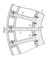
- the stator array is arranged with the stiffer stator blades A interleaved by the less stiff stator blades B.
- the blade types are distributed evenly around the array to achieve uniform global stiffness properties in the duct.
- each stator will experience the same hydrodynamic loading E as the result of flow of water over the hydrofoil surfaces.
- the free-tip (cantilever) deflections of the more flexible stators caused by the hydrodynamic loading E would create large stress and strains within the flexible stators were it not for the presence of the stiffer, interleaved stators.
- the duct between the adjacent stiff stators transfers load circumferentially between the adjacent stiff stator tips resulting in a significantly lower stresses and strains in the flexible stators when compared with the stiff stators.
- the stiff stator blades between them carry the majority of the entire structural requirements of the propulsor with the flexible stators completing the hydrodynamic form. Lower stresses and strains in the flexible stators reduce the likelihood of failure of these components.
- the use of stiffer stators minimise the effect of failure of the flexible stators in service for any reason e.g. manufacturing deficiency, shock/impact. Additionally, the reduced structural loading of the flexible stators allows simpler methods to be adopted to attach these components.
- the composite is embedded into a slot in the centrebody 10 whilst the stiffer stators are conventionally bolted or otherwise mounted to the centrebody.
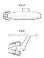
- the stator ring 8 has high stiffness stators 20 interleaved with the less stiff composite stators 22.
- the high stiffness stators are securely fastened to the mounting ring 24, or centrebody by an appropriate fastening means e.g. bolt fasteners 26.
- Slots 28 are formed in the centrebody 24 into which the composite vanes are inserted.
- a filler such as a resinous adhesive may be used to help secure the stator to the centrebody and neighbouring vanes and to present a smooth profile to the water flowing through the propulsor.
- the introduction of the composite stator vanes provides a significant weight and material saving to the propulsor.
- the relative proportion and location of stiffer stators to the more flexible stators can be varied for each vessel application to provide the necessary global system properties.
- the stiffness of the flexible stators can also be varied for a given situation by changing its material of manufacture, or providing stiffening rods.
- the overall modal frequency of the duct / stator system can be tuned to avoid detrimental noise signatures emanating from the propulsor.
- Vibration from the engine may also be controlled through the use of the tuned composites giving rise to a smoother operation. This is of particular benefit to the luxury liner market where comfort is of particular importance. In other applications it may be desirable to avoid resonance generated at particular operating speeds. By selecting an appropriate stiffness of the composite blade the signature of the propulsor can be tuned.
Landscapes
- Chemical & Material Sciences (AREA)
- Engineering & Computer Science (AREA)
- Combustion & Propulsion (AREA)
- Mechanical Engineering (AREA)
- Ocean & Marine Engineering (AREA)
- Structures Of Non-Positive Displacement Pumps (AREA)
Applications Claiming Priority (1)
| Application Number | Priority Date | Filing Date | Title |
|---|---|---|---|
| GBGB0800075.4A GB0800075D0 (en) | 2008-01-04 | 2008-01-04 | Propulsor |
Publications (2)
| Publication Number | Publication Date |
|---|---|
| EP2077227A2 true EP2077227A2 (de) | 2009-07-08 |
| EP2077227A3 EP2077227A3 (de) | 2017-06-28 |
Family
ID=39111097
Family Applications (1)
| Application Number | Title | Priority Date | Filing Date |
|---|---|---|---|
| EP08253884.4A Withdrawn EP2077227A3 (de) | 2008-01-04 | 2008-12-04 | Tauchfähige Antriebseinheit |
Country Status (4)
| Country | Link |
|---|---|
| US (1) | US8147284B2 (de) |
| EP (1) | EP2077227A3 (de) |
| AU (1) | AU2008255279B2 (de) |
| GB (1) | GB0800075D0 (de) |
Cited By (2)
| Publication number | Priority date | Publication date | Assignee | Title |
|---|---|---|---|---|
| US9097233B1 (en) * | 2010-06-01 | 2015-08-04 | Dennis Allen Ramsey | Suction-augmented hydropower turbine |
| WO2021104893A1 (de) * | 2019-11-26 | 2021-06-03 | Atlas Elektronik Gmbh | Unterwasserfahrzeug mit einem hydrodynamischen element |
Families Citing this family (3)
| Publication number | Priority date | Publication date | Assignee | Title |
|---|---|---|---|---|
| KR101447867B1 (ko) * | 2013-01-11 | 2014-10-07 | 삼성중공업 주식회사 | 후류 고정날개를 구비한 선박 |
| US9522718B2 (en) * | 2014-07-25 | 2016-12-20 | Hawkes Ocean Technologies | Positively buoyant, vertical thrust, manned submersible |
| US9440720B1 (en) * | 2015-03-16 | 2016-09-13 | Thomas Kidder Sawyer, Jr. | Tommy power paddle |
Family Cites Families (10)
| Publication number | Priority date | Publication date | Assignee | Title |
|---|---|---|---|---|
| US5597245A (en) * | 1962-08-13 | 1997-01-28 | The United States Of America As Represented By The Secretary Of The Navy | Cavitation suppressing ducted propeller system |
| FR1387903A (fr) * | 1963-11-22 | 1965-02-05 | Perfectionnements aux propulseurs pour les navires | |
| GB1323872A (en) | 1969-10-23 | 1973-07-18 | Defence Secretary For State Fo | Marine propulsion system |
| US4993977A (en) * | 1989-06-21 | 1991-02-19 | Fmc Corporation | Water jet propulsion module |
| US5220231A (en) * | 1990-08-23 | 1993-06-15 | Westinghouse Electric Corp. | Integral motor propulsor unit for water vehicles |
| US5252875A (en) * | 1990-08-23 | 1993-10-12 | Westinghouse Electric Corp. | Integral motor propulsor unit for water vehicles with plural electric motors driving a single propeller |
| US5269656A (en) * | 1992-09-30 | 1993-12-14 | The United States Of America As Represented By The Secretary Of The Navy | High damping limp propeller |
| US5607329A (en) * | 1995-12-21 | 1997-03-04 | The United States Of America As Represented By The Secretary Of The Navy | Integrated motor/marine propulsor with permanent magnet blades |
| US6572422B2 (en) * | 2000-10-10 | 2003-06-03 | Monterey Bay Aquarium Research Institute (Mbari) | Tail assembly for an underwater vehicle |
| FR2869586B1 (fr) * | 2004-04-30 | 2006-06-16 | Alstom Sa | Ensemble de propulsion pour navire, comprenant une nacelle destinee a une installation sous la carene du navire |
-
2008
- 2008-01-04 GB GBGB0800075.4A patent/GB0800075D0/en not_active Ceased
- 2008-12-04 EP EP08253884.4A patent/EP2077227A3/de not_active Withdrawn
- 2008-12-05 US US12/314,175 patent/US8147284B2/en not_active Expired - Fee Related
- 2008-12-11 AU AU2008255279A patent/AU2008255279B2/en not_active Ceased
Cited By (2)
| Publication number | Priority date | Publication date | Assignee | Title |
|---|---|---|---|---|
| US9097233B1 (en) * | 2010-06-01 | 2015-08-04 | Dennis Allen Ramsey | Suction-augmented hydropower turbine |
| WO2021104893A1 (de) * | 2019-11-26 | 2021-06-03 | Atlas Elektronik Gmbh | Unterwasserfahrzeug mit einem hydrodynamischen element |
Also Published As
| Publication number | Publication date |
|---|---|
| EP2077227A3 (de) | 2017-06-28 |
| AU2008255279B2 (en) | 2014-02-13 |
| GB0800075D0 (en) | 2008-02-13 |
| US8147284B2 (en) | 2012-04-03 |
| US20090176419A1 (en) | 2009-07-09 |
| AU2008255279A1 (en) | 2009-07-23 |
Similar Documents
| Publication | Publication Date | Title |
|---|---|---|
| US8202041B2 (en) | Fan case for turbofan engine | |
| US9228444B2 (en) | Annulus filler | |
| US8147284B2 (en) | Submersible propulsor unit | |
| JP5215734B2 (ja) | 船舶用プロペラの翼構造 | |
| EP1942253A2 (de) | Leitschaufel und Herstellungsverfahren dafür | |
| US10549830B2 (en) | Modular azimuth thruster | |
| US20080159856A1 (en) | Guide vane and method of fabricating the same | |
| US9670788B2 (en) | Composite aerofoil vane | |
| EP2713014A2 (de) | Ringförmiger Füller für Axialstrommaschine | |
| US20240093611A1 (en) | Hybridization of the fibers of the fibrous reinforcement of a fan blade | |
| JP6532050B2 (ja) | 船舶用プロペラ、及び船舶用プロペラの製造方法 | |
| CN110725721B (zh) | 用于涡轮机的具有金属紧固件的复合出口导向叶片 | |
| US7942639B2 (en) | Hybrid bucket dovetail pocket design for mechanical retainment | |
| US11174740B2 (en) | Vane comprising a structure made of composite material and a metal stiffening part | |
| US12006841B2 (en) | Hybridization of the fibers of the fibrous reinforcement of a fan blade with elastic fibers | |
| US12372001B2 (en) | Secondary flow guide vane of a turbomachine and turbomachine provided therewith | |
| JP6466061B2 (ja) | 舶用プロペラおよび舶用プロペラの改修方法 | |
| CN119429057B (zh) | 一种基于异构耦合叶片的泵喷推进器转子及设计方法 | |
| US11827323B1 (en) | Marine propeller | |
| US11912389B1 (en) | Marine propeller | |
| US12037096B1 (en) | Marine propeller | |
| EP4411110B1 (de) | Metallplattierte generativ gefertigte kunststoffrotorummantelungen und deren herstellungsverfahren | |
| CN121568873A (zh) | 用于减少水运工具推进功率需求的装置 | |
| JP2024127630A (ja) | 回転式推進装置または回転式発電装置および回転式推進装置または回転式発電装置を用いた船舶用プロペラ | |
| JP2024546298A (ja) | 浮体式風力発電用プラットフォームおよび関連する浮体式風力発電用組立品 |
Legal Events
| Date | Code | Title | Description |
|---|---|---|---|
| PUAI | Public reference made under article 153(3) epc to a published international application that has entered the european phase |
Free format text: ORIGINAL CODE: 0009012 |
|
| AK | Designated contracting states |
Kind code of ref document: A2 Designated state(s): AT BE BG CH CY CZ DE DK EE ES FI FR GB GR HR HU IE IS IT LI LT LU LV MC MT NL NO PL PT RO SE SI SK TR |
|
| AX | Request for extension of the european patent |
Extension state: AL BA MK RS |
|
| RAP1 | Party data changed (applicant data changed or rights of an application transferred) |
Owner name: ROLLS-ROYCE PLC |
|
| PUAL | Search report despatched |
Free format text: ORIGINAL CODE: 0009013 |
|
| AK | Designated contracting states |
Kind code of ref document: A3 Designated state(s): AT BE BG CH CY CZ DE DK EE ES FI FR GB GR HR HU IE IS IT LI LT LU LV MC MT NL NO PL PT RO SE SI SK TR |
|
| AX | Request for extension of the european patent |
Extension state: AL BA MK RS |
|
| RIC1 | Information provided on ipc code assigned before grant |
Ipc: B63H 5/14 20060101AFI20170524BHEP Ipc: B63H 25/42 20060101ALI20170524BHEP |
|
| STAA | Information on the status of an ep patent application or granted ep patent |
Free format text: STATUS: THE APPLICATION HAS BEEN PUBLISHED |
|
| AKX | Designation fees paid |
Designated state(s): DE FR GB NO |
|
| AXX | Extension fees paid |
Extension state: RS Extension state: MK Extension state: BA Extension state: AL |
|
| STAA | Information on the status of an ep patent application or granted ep patent |
Free format text: STATUS: THE APPLICATION IS DEEMED TO BE WITHDRAWN |
|
| 18D | Application deemed to be withdrawn |
Effective date: 20180113 |