EP2077339A2 - Procédé pour formation de liaison covalente AL-C efficace entre un matériau d'aluminium et de carbone - Google Patents
Procédé pour formation de liaison covalente AL-C efficace entre un matériau d'aluminium et de carbone Download PDFInfo
- Publication number
- EP2077339A2 EP2077339A2 EP08161045A EP08161045A EP2077339A2 EP 2077339 A2 EP2077339 A2 EP 2077339A2 EP 08161045 A EP08161045 A EP 08161045A EP 08161045 A EP08161045 A EP 08161045A EP 2077339 A2 EP2077339 A2 EP 2077339A2
- Authority
- EP
- European Patent Office
- Prior art keywords
- carbon material
- aluminum
- carbon
- covalent bond
- mixture
- Prior art date
- Legal status (The legal status is an assumption and is not a legal conclusion. Google has not performed a legal analysis and makes no representation as to the accuracy of the status listed.)
- Withdrawn
Links
Images






Classifications
-
- C—CHEMISTRY; METALLURGY
- C25—ELECTROLYTIC OR ELECTROPHORETIC PROCESSES; APPARATUS THEREFOR
- C25D—PROCESSES FOR THE ELECTROLYTIC OR ELECTROPHORETIC PRODUCTION OF COATINGS; ELECTROFORMING; APPARATUS THEREFOR
- C25D5/00—Electroplating characterised by the process; Pretreatment or after-treatment of workpieces
- C25D5/54—Electroplating of non-metallic surfaces
-
- B—PERFORMING OPERATIONS; TRANSPORTING
- B22—CASTING; POWDER METALLURGY
- B22F—WORKING METALLIC POWDER; MANUFACTURE OF ARTICLES FROM METALLIC POWDER; MAKING METALLIC POWDER; APPARATUS OR DEVICES SPECIALLY ADAPTED FOR METALLIC POWDER
- B22F1/00—Metallic powder; Treatment of metallic powder, e.g. to facilitate working or to improve properties
-
- C—CHEMISTRY; METALLURGY
- C22—METALLURGY; FERROUS OR NON-FERROUS ALLOYS; TREATMENT OF ALLOYS OR NON-FERROUS METALS
- C22C—ALLOYS
- C22C26/00—Alloys containing diamond or cubic or wurtzitic boron nitride, fullerenes or carbon nanotubes
-
- C—CHEMISTRY; METALLURGY
- C22—METALLURGY; FERROUS OR NON-FERROUS ALLOYS; TREATMENT OF ALLOYS OR NON-FERROUS METALS
- C22C—ALLOYS
- C22C32/00—Non-ferrous alloys containing at least 5% by weight but less than 50% by weight of oxides, carbides, borides, nitrides, silicides or other metal compounds, e.g. oxynitrides, sulfides, whether added as such or formed in situ
- C22C32/0084—Non-ferrous alloys containing at least 5% by weight but less than 50% by weight of oxides, carbides, borides, nitrides, silicides or other metal compounds, e.g. oxynitrides, sulfides, whether added as such or formed in situ carbon or graphite as the main non-metallic constituent
-
- C—CHEMISTRY; METALLURGY
- C22—METALLURGY; FERROUS OR NON-FERROUS ALLOYS; TREATMENT OF ALLOYS OR NON-FERROUS METALS
- C22C—ALLOYS
- C22C47/00—Making alloys containing metallic or non-metallic fibres or filaments
- C22C47/02—Pretreatment of the fibres or filaments
-
- C—CHEMISTRY; METALLURGY
- C22—METALLURGY; FERROUS OR NON-FERROUS ALLOYS; TREATMENT OF ALLOYS OR NON-FERROUS METALS
- C22C—ALLOYS
- C22C49/00—Alloys containing metallic or non-metallic fibres or filaments
- C22C49/02—Alloys containing metallic or non-metallic fibres or filaments characterised by the matrix material
- C22C49/04—Light metals
- C22C49/06—Aluminium
-
- C—CHEMISTRY; METALLURGY
- C25—ELECTROLYTIC OR ELECTROPHORETIC PROCESSES; APPARATUS THEREFOR
- C25D—PROCESSES FOR THE ELECTROLYTIC OR ELECTROPHORETIC PRODUCTION OF COATINGS; ELECTROFORMING; APPARATUS THEREFOR
- C25D3/00—Electroplating: Baths therefor
- C25D3/02—Electroplating: Baths therefor from solutions
- C25D3/42—Electroplating: Baths therefor from solutions of light metals
- C25D3/44—Aluminium
-
- C—CHEMISTRY; METALLURGY
- C22—METALLURGY; FERROUS OR NON-FERROUS ALLOYS; TREATMENT OF ALLOYS OR NON-FERROUS METALS
- C22C—ALLOYS
- C22C26/00—Alloys containing diamond or cubic or wurtzitic boron nitride, fullerenes or carbon nanotubes
- C22C2026/002—Carbon nanotubes
-
- Y—GENERAL TAGGING OF NEW TECHNOLOGICAL DEVELOPMENTS; GENERAL TAGGING OF CROSS-SECTIONAL TECHNOLOGIES SPANNING OVER SEVERAL SECTIONS OF THE IPC; TECHNICAL SUBJECTS COVERED BY FORMER USPC CROSS-REFERENCE ART COLLECTIONS [XRACs] AND DIGESTS
- Y10—TECHNICAL SUBJECTS COVERED BY FORMER USPC
- Y10T—TECHNICAL SUBJECTS COVERED BY FORMER US CLASSIFICATION
- Y10T428/00—Stock material or miscellaneous articles
- Y10T428/29—Coated or structually defined flake, particle, cell, strand, strand portion, rod, filament, macroscopic fiber or mass thereof
- Y10T428/2913—Rod, strand, filament or fiber
- Y10T428/2918—Rod, strand, filament or fiber including free carbon or carbide or therewith [not as steel]
-
- Y—GENERAL TAGGING OF NEW TECHNOLOGICAL DEVELOPMENTS; GENERAL TAGGING OF CROSS-SECTIONAL TECHNOLOGIES SPANNING OVER SEVERAL SECTIONS OF THE IPC; TECHNICAL SUBJECTS COVERED BY FORMER USPC CROSS-REFERENCE ART COLLECTIONS [XRACs] AND DIGESTS
- Y10—TECHNICAL SUBJECTS COVERED BY FORMER USPC
- Y10T—TECHNICAL SUBJECTS COVERED BY FORMER US CLASSIFICATION
- Y10T428/00—Stock material or miscellaneous articles
- Y10T428/29—Coated or structually defined flake, particle, cell, strand, strand portion, rod, filament, macroscopic fiber or mass thereof
- Y10T428/2982—Particulate matter [e.g., sphere, flake, etc.]
Definitions
- the present invention relates to a method for Al-C covalent bond formation using an electric arc or an electrochemical technique.
- Aluminum is used in a broad range of applications, ranging from daily products, such as kitchen foil, disposable tableware, and the like, to durable goods, such as windows, vehicles, aircrafts, and so forth.
- Aluminum is characterized by light weight that is only a third of that of steel, and has superior strength through alloying with other metals.
- aluminum is chemically stable because a chemically stable oxide layer existing on an aluminum surface prevents corrosion from being caused by moisture or oxygen.
- aluminum has been widely used in vehicles, aircrafts, etc.
- aluminum wheels employed in vehicles are lighter than conventional steel wheels, and thus can reduce their own loads, which contributes to improving in fuel efficiency, as well as decreasing the weight of a vehicle body.
- structural aluminum materials such as structural tubes or sheets
- structural aluminum materials must be thick because aluminum has tensile strength corresponding to only about 40% of that of steel, which lead to excessive consumption of materials and thus excessive cost of materials.
- Korean Patent Laid-Open Publication No. 10-2003-0046378 discloses a method of producing joint materials suitable for structural materials by integrating carbon fibers and aluminum by use of additives.
- this method has a limitation on an interfacial bonding force between aluminum and a carbon material due to the use of additives, and is problematic in that adhesive strength is lowered because joint materials must be deformed for shaping thereof.
- the method using plasma is a method in which a carbon material is sintered by melting aluminum in a moment through high-energetic plasma.
- An example thereof is disclosed in Japanese Patent Laid-Open Publication No. 2006-315893 (2006.11.24 ).
- the method using plasma has a disadvantage in that the productivity is lowered since the apparatus is expensive and high frequency needs to be applied for a long time.
- the electroplating means a method of preparing a composite material plating solution, applying a potential, and plating a composite material (Japanese Patent Laid-Open Publication No. 2007-070689 ).
- a carbon nanotube and aluminum are dissolved in a plating solution so that the two materials can reach the surface of the cathode, thereby forming a complex.
- the present invention has been made to solve at least the above-mentioned problems occurring in the prior art, and the present inventors has solved the existing problem of bonding between aluminum and a carbon material by using an electric arc or an electrochemical technique.
- the method of electric arc induces an Al-C covalent bond by generating electric arc or Joule heat within the compound of carbon nanotube and aluminum when the electrons flow between a carbon material and aluminum.
- the electrochemical technique allows carbon included in a carbon material to form an Al-C covalent bond by reacting with aluminum that is reduced by a potential difference.
- a method for covalent bond formation between aluminum and a carbon material including the steps of: (i) introducing defects in a carbon material to thereby functionalize the carbon material; (ii) mixing the functionalized carbon material with aluminum to thereby obtain a mixture; and (iii) inducing an Al-C covalent bond by applying an electric arc to the mixture.
- At least one or two kinds of materials selected from the group consisting of graphite, a graphite fiber, a carbon fiber, a carbon nanofiber, and a carbon nanotube may be used as the carbon material.
- a carbon material available at present has a diameter of 0.4 nm to 16 ⁇ m and a length of 10 nm to 10 cm. That is, according to the data reported so far ( Science 292, 2462 (2001 )), a carbon nanotube is known to have a minimum diameter of 0.4 nm, and a commercialized carbon fiber is known to have a maximum diameter of 16 ⁇ m (Taiwan Carbon Technology Co).
- a carbon fiber (Toray) with a diameter of 7 to 8 ⁇ m and a length of 5 mm was also used.
- no limitation is imposed on the size of a carbon material.
- the carbon material may be treated with acid.
- Acid used in such an acid treatment may include nitric acid (HNO 3 ), sulfuric acid (H 2 SO 4 ), or a mixture of nitric acid and sulfuric acid.
- a carbon nanotube forms a sp 2 -hybridized bond, and has a cylindrical-shaped structure.
- defects of carbon nanotube, such as a groove or functional group is formed therein so that it can bond with a matrix.
- functionalizing a carbon material refers to enhancing the reactivity of a carbon material by attaching a functional group with specific reactivity, such as -OH, -COOH, -CHO, etc., to the carbon material.
- the carbon material may be treated with a microwave.
- a solvent is used in such a microwave treatment, and the solvent may include any one kind of material or a mixture of at least two kinds of materials selected from the group consisting of ethylene glycol, nitric acid (HNO 3 ), and sulfuric acid (H 2 SO 4 ).
- the microwave treatment may be carried out for 1 to 10 minutes.
- the carbon material may be treated with plasma.
- a plasma treatment any one kind of gas or a mixture of at least two kinds of gases selected from the group consisting of oxygen, argon, and helium may be used.
- an electric power of 50 to 1000 W and a treatment time of 1 minute to 1 hour may be used in the plasma treatment.
- step (i) the method of the present invention is not limited thereto.
- the term "functionalize” as used herein means forming defects in a carbon material and attaching functional groups to the defects.
- a ball mill treatment or an ultrasonic dispersion treatment in a liquid may be employed.
- the carbon material may be mixed with aluminum in a mixing ratio of 0.1 to 50% by weight.
- the ball mill treatment aluminum and the carbon material, together with balls, are put into a steel vessel, and ball milling is conducted under an inert gas atmosphere to obtain mixed aluminum/carbon powder.
- the ultrasonic dispersion treatment in a liquid carbon material and aluminum particles are dispersed in ethanol or deionized water, and then the dispersed particles are subjected to drying and filtering.
- arc discharge may be induced by applying a pulse current to the mixture of the carbon material and aluminum.
- a method of fabricating an aluminum-carbon material composite comprising the steps of:(i) introducing defects in a carbon material to thereby functionalize the carbon material;(ii) mixing the functionalized carbon material with aluminum to thereby obtain a mixture; and (iii) inducing an Al-C covalent bond by applying an electric arc to the mixture.
- step (i) may be performed by treatment of acid, microwave, or plasma, as described above.
- the condition of the ball milling, the ultrasonic dispersion treatment in a liquid, arc discharge, and the feature of the carbon material are the same as those described above.
- an aluminum-carbon material compoxite fabricated according to the above method.
- a method for covalent bond formation between aluminum and a carbon material including the steps of: (i) providing an electrochemical apparatus including an anode and a cathode with a carbon material connected thereto; (ii) filling the electrochemical apparatus with an electrolyte containing an organic solvent, a solubilizing agent, a reductant, and an aluminum compound; and (iii) plating a surface of the carbon material connected to the cathode with aluminum by applying a potential to the electrochemical apparatus.
- an electrochemical cell may be used as the electrochemical apparatus.
- step (i) at least one or two kinds of materials selected from the group consisting of graphite, a graphite fiber, a carbon fiber, a carbon nanofiber, and a carbon nanotube may be used as the carbon material.
- a carbon material available at present has a diameter of 0.4 nm to 16 ⁇ m and a length of 10 nm to 10 cm. That is, according to the data reported so far ( Science 292, 2462 (2001 )), a carbon nanotube is known to have a minimum diameter of 0.4 nm, and a commercialized carbon fiber is known to have a maximum diameter of 16 ⁇ m (Taiwan Carbon Technology Co).
- a carbon fiber (Toray) with a diameter of 7 to 8 ⁇ m and a length of 5 mm was also used.
- no limitation is imposed on the size of a carbon material.
- the organic solvent used in step (ii) may include any one kind of solvent or a mixture of at least two kinds of solvents selected from the group consisting of nonprotonic ethers, such as tetrahydrofurane (THF), dimethyl ether, diethyl ether, t-butyl ether, iso-amyl ether, phenyl ether, and methyl-t-butyl ether, and ionic liquids, such as ethylpyridinium halide, N-(1-butyl)pyridinium halide, 1-methyl-3-ethylimidazolium halide, and trimethylphenylammonium halide.
- the organic solvent is not limited thereto.
- an organic solvent for preparing the electrolyte must satisfy some conditions.
- the organic solvent must be durable enough not to decompose at a potential lower than -1.67V (vs. SHE), which is a potential where aluminum is reduced.
- the organic solvent must be a polar solvent capable of easily dissolving the aluminum compound so as to provide a high-concentration aluminum solution.
- the organic solvent must be a Lewis base which can form a coordinate bond with an aluminum ion by reacting with a Lewis acid.
- the solubilizing agent used for providing a high-concentration electrolyte in step (ii) may include, but may not be limited to, any one kind of material or a mixture of at least two kinds of materials selected from the group consisting of aromatic hydrocarbons, such as benzene, phenol, toluene, xylene, and mesitylene.
- the reductant used for accelerating precipitation of aluminum in step (ii) may include, but may not be limited to, any one material selected from the group consisting of lithium aluminum hydride (LiAlH 4 ), lithium hydride (LiH), sodium borohydride (NaBH 4 ), and lithium chloride (LiCl).
- LiAlH 4 lithium aluminum hydride
- LiH lithium hydride
- NaBH 4 sodium borohydride
- LiCl lithium chloride
- the aluminum compound used for aluminum plating in step (ii) may include, but may not be limited to, any one selected from the group consisting of aluminum halides (AlXx) and organoaluminum compounds.
- the potential applied to the electrochemical apparatus in step (iii) may be equal to or less than a potential where aluminum is reduced. Therefore, the potential may vary with an organic solvent to be used. For example, when THF belonging to nonprotonic ethers is used as the organic solvent, a potential, ranging from - 5 V to -1.67 V (vs. SHE) where aluminum is reduced, may be applied. Also, when ethylpyridinium halide belonging to ionic liquids is used as the organic solvent, a potential of -10 V to -1.67 V (vs. SHE) may be applied.
- a method of fabricating an aluminum-carbon material composite comprising the steps of: (i) providing an electrochemical apparatus including an anode and a cathode with a carbon material connected thereto; (ii) filling the electrochemical apparatus with an electrolyte containing an organic solvent, a solubilizing agent, a reductant, and an aluminum compound; and (iii) plating a surface of the carbon material connected to the cathode with aluminum by applying a potential to the electrochemical apparatus so as to form a covalent bond between the aluminum and the carbon material.
- organic solvent, the solubilizing agent, the reductant, and the aluminum compound in step (ii), and the condition of the applied potential and the feature of the carbon material in step (iii) are the same as those described above.
- an aluminum-carbon material composite fabricated according to the above method.
- the existing problem of bonding between aluminum and a carbon material is solved using an electric arc or an electrochemical technique.
- the electric arc induces an Al-C covalent bond by generating electric arc or Jule heat within a test material when electrons flow between a carbon material and aluminum.
- the electrochemical technique allows carbon included in a carbon material to form an Al-C covalent bond by reacting with aluminum that is reduced by a potential difference.
- An aluminum/carbon material composite prepared according to the present invention is light in weight, excellent in mechanical strength, applicable to vehicle parts and aluminum wheels in use.
- the present invention provides a method for covalent bond formation between aluminum and a carbon material, the method including the steps of: (i) introducing defects in a carbon material to thereby functionalize the carbon material; (ii) mixing the functionalized carbon material with aluminum to thereby obtain a mixture; and (iii) inducing an Al-C covalent bond by applying an electric arc to the mixture.
- the present invention provides a method for covalent bond formation between aluminum and a carbon material, the method including the steps of: (i) providing an electrochemical apparatus including an anode and a cathode with a carbon material connected thereto; (ii) filling the electrochemical apparatus with an electrolyte containing an organic solvent, a solubilizing agent, a reductant, and an aluminum compound; and (iii) plating a surface of the carbon material connected to the cathode with aluminum by applying a potential to the electrochemical apparatus.
- Example 1 Process of inducing Al-C covalent bond between aluminum and carbon material by using electric arc
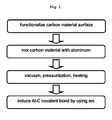
- FIG. 1 Particulars of the present invention follow an experimental process in FIG. 1 .
- a multi-walled carbon nanotube ILJIN Nanotech, CM95
- an NK carbon nanotube Nano-Karbon, hellow CNT 75
- a carbon fiber Toray - Japan, T 300
- the multi-walled carbon nanotube had a diameter of 10 to 20 nm and a length of 10 to 20 ⁇ m
- the NK carbon nanotube had a diameter of 40 to 60 nm and a length of about 20 ⁇ m
- the carbon nanotube was functionalized by being subjected to an ultrasonic reaction in 70% nitric acid (HNO 3 ) contained in a water tank-type sonicator for 10 minutes to 3 hours.
- the NK carbon nanotube was purchased as a functionalized product.
- the carbon fiber was functionalized by being subjected to an ultrasonication in a 1:1 mixture of sulfuric acid (H 2 SO 4 ) and nitric acid (HNO 3 ) for 2 hours.
- a carbon material was functionalized through a microwave treatment in such a manner that ethylene glycol or nitric acid (HNO 3 ) was used as a solvent, sodium chlorate (NaClO 3 ) was used as a oxidation agent, and the multi-walled carbon nanotube was dispersed in the solvent.
- the microwave treatment was carried out in a microwave oven (KR-U20AB, Daewoo Electronics, Korea) for 3 minutes. It was possible to set a treatment time within a range of 1 to 6 minutes.
- a plasma treatment for the multi-walled carbon nanotube was carried out under atmospheric pressure by using a power consumption of 500 W, and using 500 seem of oxygen and 300 seem of helium as a gaseous material.
- the multi-walled carbon nanotube was treated with plasma for 5 minutes by using an A-tech system product to thereby introduce defects in the carbon nanotube and functionalize the carbon material.
- each collected carbon material mixed into aluminum was poured into a graphite mold with a diameter of 2cm to thereby prepare a sample for each carbon material, and a vacuum atmosphere of 10 -2 to 10 -6 torr was formed. Also, each sample was pressurized with a pressure of 30 to 2000 MPa, and then temperature is elevated. The elevated temperature could range from room temperature to 1000 °C. Next, an Al-C covalent bond between the carbon material and aluminum was induced by applying a pulse current to induce arc discharge.
- Example 2 Sample observation after inducing Al-C covalent bond between aluminum and carbon material by using electric arc
- FIG. 2 illustrates photographs of samples, which were taken by a digital camera (koolpix-3700, Nikon) before and after an Al-C covalent bond between aluminum and each carbon material was induced using an electric arc.
- FIG. 2(a) is a photograph taken before a multi-walled carbon nanotube (MWCNT) was not mixed with aluminum
- FIG. 2(b) is a photograph taken after the MWCNT and aluminum samples in FIG. 2(a) were mixed, and then were induced to bond with each other by using an electric arc.
- MWCNT multi-walled carbon nanotube
- FIG. 2(b) is a photograph taken after the MWCNT and aluminum samples in FIG. 2(a) were mixed, and then were induced to bond with each other by using an electric arc.
- the MWCNT was not externally visible, and thus it could be noted that the MWCNT did not fall out of an aluminum matrix.
- Measured apparent density was 2.63 g/cm 3 , which was lower than that of common aluminum, and thus it could be expected that the MWCNT was included within the aluminum matrix.
- FIG. 2(c) is a photograph taken before an NK carbon nanotube (NKCNT) was mixed with aluminum.
- the NKCNT had a diameter greater than that of a common multi-walled carbon nanotube, and thus it could be observed that the apparent volume of the NKCNT was greater than that of aluminum.
- FIG. 2(d) is a photograph taken after the NKCNT and aluminum samples in FIG. 2(c) were mixed, and then were induced to bond with each other by using an electric arc. Similar to the result of observing the photographs in FIGS. 2(a) and 2(b) , it could be noted that the NKCNT did not fall out of an aluminum matrix. Measured apparent density was 2.68 g/cm 3 , which meant that the same result as in FIGS. 2(a) and 2(b) was obtained.
- FIG. 2(e) is a photograph taken before a carbon fiber was mixed with aluminum. It could be observed that the carbon fiber had apparent volume greater than that of aluminum. Also, FIG. 2(f) is a photograph taken after an electric arc was generated for the carbon fiber and aluminum samples in FIG. 2(e) . Similar to other carbon materials, it could be noted that the carbon fiber was not externally revealed. Measured apparent density was 2.55 g/ cm 3 , which also meant that the same result as in FIGS. 2(a) and 2(b) was obtained, and thus it could be noted that the carbon fiber was included within aluminum.
- Example 3 Electron microscopic analysis of sample surface after inducing Al-C covalent bond between aluminum and carbon material by using electric arc
- FIG. 3 illustrates photographic analysis data of sample surfaces, measured by an electron microscope (JSM7000F, JEOL) after an Al-C covalent bond between aluminum and a carbon material was induced using an electric arc.
- FIG. 3(a) is an electron microscopic photograph of a sample surface, taken after an Al-C covalent bond between aluminum and a multi-walled carbon nanotube was induced
- FIG. 3(b) is an electron microscopic photograph of the multi-walled carbon nanotube before the experiment. Comparing these two photographs in consideration of the same magnification thereof, it could be noted that the multi-walled carbon nanotube was not externally revealed.
- FIGS. 3(c) and 3(d) are electron microscopic photographs taken before and after an Al-C covalent bond between aluminum and an NK carbon nanotube was induced. Comparing these two photographs in consideration of the same magnification thereof, as in the experiment for the multi-walled carbon nanotube, it could be noted that the NK carbon nanotube was not externally revealed.
- FIGS. 3(e) and 3(f) are electron microscopic photographs taken after an Al-C covalent bond between aluminum and a carbon fiber was induced.
- the photograph of FIG. 3(e) was taken with a magnification of 100x
- the photograph of FIG. 3(f) was taken with a magnification of 1,000x.
- the diameter of the carbon fiber was 7 to 8 ⁇ m, corresponding to a size observable in an optical photograph.
- the carbon fiber might be observed in a photograph with a magnification of 100x.
- no carbon fiber was externally observed in an Al-C covalent bond-induced sample according to the method of the present invention. Therefore, it could be noted that the carbon fiber did not fallout of an aluminum matrix.
- Example 4 Analysis of sample cross section after inducing Al-C covalent bond between aluminum and multi-walled carbon nanotube
- FIGS. 4(a) and 4(b) are photographs of sample cross sections, taken by an electron microscope (JSM7000F, JEOL) after an Al-C covalent bond between aluminum and a multi-walled carbon nanotube was induced.
- JSM7000F, JEOL electron microscope
- FIGS. 4(b) are photographs of sample cross sections, taken by an electron microscope (JSM7000F, JEOL) after an Al-C covalent bond between aluminum and a multi-walled carbon nanotube was induced.
- JSM7000F electron microscope
- JEOL electron microscopic analysis was conducted for the cross section of a sample so as to photographically verify the actual existence of a carbon nanotube.
- FIG. 4(b) it could be noted from FIG. 4(b) that the multi-walled carbon nanotube existed within the sample.
- FIGS. 4(c) and 4(d) are photographs taken after aluminum was etched with hydrochloric acid so as to specifically verify the existence of the multi-walled carbon nanotube. As a result of this, a part of the multi-walled carbon nanotube was detected in an aluminum surface portion etched with hydrochloric acid.
- Example 5 Raman analysis for verifying crystallinity of carbon material that forms covalent bond with aluminum by electric arc
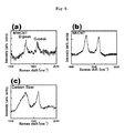
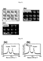
- FIGS. 5(a), 5(b) and 5(c) are Raman analysis data of surfaces of aluminum samples, each of which bonded with a multi-walled carbon nanotube, an NK carbon nanotube, and a carbon fiber.
- a G-peak vibration mode corresponding to crystal vibration of the carbon sp 2 hybridized bond of a carbon material could be detected in the Raman analysis data of all the samples.
- the sp 2 hybridized bond is a structure indicative of the crystallinity of graphite, and the main framework of a carbon nanotube, a carbon material, and the like is formed by the sp 2 hybridized bond. From this result, it could be noted that the crystallinity of a covalent bonded carbon material within an aluminum sample was not destroyed and was maintained intact in the course of electric arc micro bonding.
- Example 6 X-ray diffraction analysis of aluminum/carbon material that forms covalent bond by electric arc
- FIG. 6 illustrates X-ray diffraction analysis data measured before and after an Al-C covalent bond between aluminum and a carbon material was induced.
- FIG. 6(a) is X-ray diffraction analysis data measured after a multi-walled carbon nanotube was mixed with aluminum. A peak for an aluminum crystal could be detected in the X-ray diffraction analysis data.
- FIG. 6(b) is X-ray diffraction analysis data measured after electric arc bonding was conducted for the sample of FIG. 6(a) . In this data, diffraction peaks of aluminum carbide (Al 4 C 3 ) could be detected at angles of 31.11° (double), 40.0° and 55.0°. From this result, it could be noted that a covalent bond between the multi-walled carbon nanotube and aluminum was formed in the sample.
- FIGS. 6(c) and 6(d) are X-ray diffraction analysis data measured before and after electric arc bonding was conducted between aluminum and an NK carbon nanotube.
- X-ray diffraction peaks of aluminum carbide were detected after the electric arc bonding, in the case of the NK carbon nanotube.
- a covalent bond between aluminum and carbon was also formed in the NK carbon nanotube.
- FIGS. 6 (e) and 6(f) are X-ray diffraction analysis data for a carbon fiber. In this data, it could be noted that the above-mentioned result was also obtained in the carbon fiber.
- Example 7 Hardness analysis of sample with covalent bond formation between aluminum and carbon material by use of electric arc
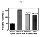
- FIG. 7 illustrates data indicating hardness values of aluminum samples containing a carbon material.
- hardness was measured five times at different locations by using a Vickers hardness testing machine (MVK-H2, AKASHI, Japan).
- a multi-walled carbon nanotube showed the highest hardness.
- hardness was trebled or more as compared to commonly used aluminum (A356-T6). Next, hardness was higher in order of an NK carbon nanotube and a carbon fiber.
- the multi-walled carbon nanotube has a tensile strength of 63GPa (Reference: http://en.wikipedia.org/wiki/Carbon_nanotube), and the carbon fiber has a tensile strength of 3.5GPa (Reference: Toray Industries).
- 63GPa http://en.wikipedia.org/wiki/Carbon_nanotube
- 3.5GPa Reference: Toray Industries
- Example 8 Process of inducing Al-C covalent bond by using electrochemical technique
- THF was used as an organic solvent for preparing an electrolyte, and benzene was added so as to provide a high-concentration electrolyte. Also, in order to enhance the activity of an electrolyte, lithium aluminum hydride (LiAlH 4 ) was added. Aluminum chloride (AlCl 3 ) with high purity and without moisture was used as an aluminum compound. All operations for preparing an electrolyte were performed in a glove box which was free from moisture and was filled with argon gas.
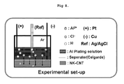
- FIG. 8 schematically illustrates an electrochemical apparatus for performing an electrochemical technique according to the present invention
- FIG. 9 illustrates the overall procedure of the electrochemical technique. Reference will now be made to the electrochemical technique according to the present invention, with reference to FIGS. 8 and 9 .
- the electrochemical apparatus used a vial with a size of 15 ml.
- a copper film was used as an electron collector capable of providing a carbon nanotube with a potential.
- the copper film was washed with acid to thereby remove an oxide layer from the surface of the copper film.
- the pickled copper film was cleanly washed with distilled water again, and then was subjected to moisture removal with acetone. As seen from FIG. 8 , the pickled copper film was laid in a lower portion of the 15ml vial.
- NK carbon nanotube was placed on the copper film.
- the NK carbon nanotube was subjected to a heat treatment at a temperature of 1000 °C under an argon atmosphere for 1 hour.
- the electrochemical apparatus was covered by an ion exchange membrane so that the NK carbon nanotube improved in conductivity through the above process does not touch a counter electrode.
- An electrically and chemically stable platinum network was used as the counter electrode.
- the platinum network was inserted into the vial to the extent that it did not reach the ion exchange membrane, and then the vial was sealed.
- An aperture with a size of about 0.5 mm was punctured in the sealed vial, and the vial was vacuumized in a vacuum chamber.
- the vial was left in vacuum to thereby completely remove moisture within the NK carbon nanotube and the electrochemical apparatus, and then the vial was filled with argon.
- a reference electrode was washed, and then was brought in the electrochemical apparatus. After all the operations were completed, the electrolyte was injected into the electrochemical apparatus. An Al-C covalent bond between aluminum and the carbon material was induced by applying a potential ranging from -5V where THF would not decompose and -1.67V (vs. SHE) where aluminum might be reduced. After a time of 20 minutes elapsed, it could be verified that the carbon nanotube was covered by aluminum, as a result of electro microscopy.
- Example 9 Electron microscopic analysis after inducing Al-C covalent bond between aluminum and carbon material by using electrochemical technique
- FIG. 10 illustrates electron microscopic photographs taken before and after an Al-C covalent bond between aluminum and an NK carbon nanotube was induced.
- FIG. 10(a) is an electron microscopic photograph taken before an Al-C covalent bond of the NK carbon nanotube was induced
- FIGS. 10(b) and 10(c) are electron microscopic photographs, each taken after an Al-C covalent bond was induced at -4V and -5V vs. Ag/AgCl Ref. Comparing the photograph of FIG. 10(a) taken before Al-C covalent bond inducement with the photographs of FIGS. 10(b) and 10(c) taken after Al-C covalent bond inducement, it could be noted that a translucent object believed to be aluminum was covered over the surface of the NK carbon nanotube.
- FIG. 11 illustrates EDS (Energy Dispersive X-ray Spectroscopy) mapping analysis data measured after an Al-C covalent bond was induced by an electrochemical reaction at -3V.
- the EDS was carried out using an appendage to an electron microscope (model no. JSM7000F, JEOL, Japan), and as a result of the EDS, aluminum was identified. Therefore, it could be noted that the above object covering the NK carbon nanotube in FIGS. 10(b) and 10(c) was aluminum.
- Example 10 Raman analysis for verifying crystallinity of carbon material that forms covalent bond with aluminum by electrochemical technique
- FIGS. 12(a) and 12(b) are Raman analysis data before and after Al-C covalent bond inducement. Even after Al-C covalent bond formation, a G-peak vibration mode corresponding to crystal vibration of the carbon sp 2 hybridized bond of a carbon material could be detected in the Raman analysis data. Therefore, it could be noted that the crystallinity of the carbon nanotube was maintained intact even after Al-C covalent bond formation.
- Example 11 XPS analysis of aluminum/carbon material that forms covalent bond by electrochemical technique
- FIG. 13 illustrates XPS analysis data of aluminum 2p.
- the XPS measures regions located within several nanometers from a surface, it can analyze a surface oxide layer and an internal Al-C covalent bond layer of aluminum. From this result, it could be noted that an Al-C covalent bond between aluminum and the carbon nanotube was actually formed.
- Example 12 X-ray diffraction analysis of aluminum/carbon material that forms covalent bond by electrochemical technique
- FIG. 14 illustrates X-ray diffraction analysis data measured after an electrochemical reaction was carried out according to potentials.
- data for a carbon nanotube without any electrochemical reaction is presented in the lowest portion, and data according to various potentials are presented in order of -2V to -5V, from the bottom to the top.
- peaks of aluminum metal crystals appeared at angles of 38.5°, 44.7°, 65.1° and 78.2°.
- an X-ray diffraction peak was detected at an angle of about 31°, which was a peak of aluminum carbide indicative of an Al-C covalent bond. From this result, it could be noted that a covalent bond between aluminum and carbon was formed using the electrochemical technique.
- a carbon material/aluminum composite prepared according to the present invention is light in weight, excellent in mechanical strength, and applicable to vehicle parts and aluminum wheels in use. Also, the carbon material/aluminum composite of the present invention is expected to extend the aluminum wheel market to commercial vehicles and large-sized trucks beyond automobiles. Moreover, it is expected that the inventive composite can be utilized as materials of aircrafts, spacecrafts, ships, etc., requiring high strength. Finally, the inventive composite is expected to be applicable to computer parts, various cooler parts, and the like due to its high thermal conductivity.
Landscapes
- Chemical & Material Sciences (AREA)
- Engineering & Computer Science (AREA)
- Materials Engineering (AREA)
- Metallurgy (AREA)
- Organic Chemistry (AREA)
- Mechanical Engineering (AREA)
- Chemical Kinetics & Catalysis (AREA)
- Electrochemistry (AREA)
- Carbon And Carbon Compounds (AREA)
- Manufacture Of Alloys Or Alloy Compounds (AREA)
- Powder Metallurgy (AREA)
- Electroplating Methods And Accessories (AREA)
Applications Claiming Priority (1)
| Application Number | Priority Date | Filing Date | Title |
|---|---|---|---|
| KR1020080001233A KR100907334B1 (ko) | 2008-01-04 | 2008-01-04 | 알루미늄과 탄소재료 간의 공유결합을 형성하는 방법, 알루미늄과 탄소재료 복합체를 제조하는 방법 및 그 방법에 의하여 제조된 알루미늄과 탄소재료 복합체 |
Publications (2)
| Publication Number | Publication Date |
|---|---|
| EP2077339A2 true EP2077339A2 (fr) | 2009-07-08 |
| EP2077339A3 EP2077339A3 (fr) | 2012-03-21 |
Family
ID=40521842
Family Applications (1)
| Application Number | Title | Priority Date | Filing Date |
|---|---|---|---|
| EP08161045A Withdrawn EP2077339A3 (fr) | 2008-01-04 | 2008-07-24 | Procédé pour formation de liaison covalente AL-C efficace entre un matériau d'aluminium et de carbone |
Country Status (5)
| Country | Link |
|---|---|
| US (1) | US20090176090A1 (fr) |
| EP (1) | EP2077339A3 (fr) |
| JP (2) | JP5296439B2 (fr) |
| KR (1) | KR100907334B1 (fr) |
| CN (2) | CN101475171A (fr) |
Cited By (4)
| Publication number | Priority date | Publication date | Assignee | Title |
|---|---|---|---|---|
| EP2394952A4 (fr) * | 2009-02-05 | 2014-05-07 | Res & Business Foundation Of Sungkyunkwan University | Nanoparticules élaborées à partir de nanotube de carbone et procédé d'élaboration correspondant |
| CN107201489A (zh) * | 2017-06-22 | 2017-09-26 | 安徽银力铸造有限公司 | 一种7b04铝合金的脉冲电场结合电流、微波固溶时效热处理的工艺方法 |
| CN110551923A (zh) * | 2019-10-08 | 2019-12-10 | 中南大学 | 一种铝基复合材料的制备方法 |
| CN111809075A (zh) * | 2020-07-03 | 2020-10-23 | 西安石油大学 | 一种Ti镀层Ti3AlC2颗粒增强Al基内燃机活塞连杆及其制造方法 |
Families Citing this family (19)
| Publication number | Priority date | Publication date | Assignee | Title |
|---|---|---|---|---|
| KR101123893B1 (ko) | 2009-02-24 | 2012-03-23 | (주) 디에이치홀딩스 | 탄소나노튜브(cnt)-알루미늄 복합재료의 제조방법 |
| WO2011005494A1 (fr) * | 2009-06-24 | 2011-01-13 | Third Millennium Metals, Llc | Composition de cuivre-carbone |
| KR101229291B1 (ko) | 2009-12-30 | 2013-02-04 | 한국기술교육대학교 산학협력단 | 탄소나노튜브 및 구리의 나노-복합소재를 첨가한 알루미늄 합금의 제조방법 |
| JP2013518991A (ja) | 2010-02-04 | 2013-05-23 | サード ミレニアム メタルズ エル エル シー | 金属−炭素複合体 |
| KR101243311B1 (ko) | 2010-11-16 | 2013-03-13 | 한국전기연구원 | 열전도성 점착제의 제조방법 및 이에 의해 제조된 열전도성 점착제를 이용한 열전도성 점착제 쉬트 |
| WO2012093668A1 (fr) * | 2011-01-05 | 2012-07-12 | ディップソール株式会社 | Bain galvanoplastique électrique de sels fusionnés d'alliage d'aluminium ou d'aluminium, permettant d'obtenir un bon pouvoir de pénétration, procédé de galvanoplastie et procédé de prétraitement utilisant un tel bain |
| TWI429586B (zh) * | 2011-02-01 | 2014-03-11 | Univ Chang Gung | Preparation of graphene nanobelt |
| MX2013010080A (es) * | 2011-03-04 | 2014-04-16 | Third Millennium Metals Llc | Composiciones de aluminio-carbono. |
| JP5723058B2 (ja) * | 2012-03-09 | 2015-05-27 | リサーチ アンド ビジネス ファンデーション ソンギュングァン ユニバーシティResearch & Business Foundation Sungkyunkwan University | 板型炭素ナノ粒子製造方法及びそれを用いたアルミニウム‐炭素の複合材料の製造方法 |
| JP2015227498A (ja) | 2014-06-02 | 2015-12-17 | 矢崎総業株式会社 | アルミニウム基複合材料及びその製造方法 |
| KR101591454B1 (ko) * | 2014-10-07 | 2016-02-03 | 주식회사 동희홀딩스 | 금속 및 산화물로 하이브리드 코팅된 나노카본의 제조방법 |
| WO2016145201A1 (fr) * | 2015-03-10 | 2016-09-15 | Massachusetts Institute Of Technology | Composites métal-nanostructures |
| KR101772031B1 (ko) | 2015-06-22 | 2017-08-28 | 창원대학교 산학협력단 | 표면 개질을 통한 마그네시아-카본 내화물에 함유된 흑연의 항산화성 증진 방법 및 이에 의해 제조된 마그네시아-카본 내화물 |
| KR101697255B1 (ko) * | 2015-06-29 | 2017-01-17 | 전북대학교산학협력단 | 전기화학법을 이용한 알루미늄 산화 나노섬유의 형성 방법 및 이에 의한 알루미늄 산화 나노섬유 |
| KR101740883B1 (ko) | 2016-03-04 | 2017-05-30 | 한국과학기술연구원 | 교반주조법을 이용한 탄소섬유 강화 알루미늄 복합재의 제조방법 |
| US10662509B2 (en) * | 2016-09-09 | 2020-05-26 | Uchicago Argonne, Llc | Method for making metal-carbon composites and compositions |
| US12293852B2 (en) | 2018-09-21 | 2025-05-06 | Massachusetts Institute Of Technology | Mixed ionic-electronic conductive materials for alkali metal transport during battery cycling, and batteries incorporating same |
| WO2020061565A1 (fr) | 2018-09-21 | 2020-03-26 | Massachusetts Institute Of Technology | Procédés et appareil pour faciliter le transport de métaux alcalins pendant un cyclage de batterie, et batteries les incorporant |
| CN110054175B (zh) * | 2019-04-24 | 2022-09-16 | 安徽理工大学 | 铝/多壁碳纳米管复合材料、制备方法和应用 |
Citations (4)
| Publication number | Priority date | Publication date | Assignee | Title |
|---|---|---|---|---|
| US5338712A (en) * | 1993-02-04 | 1994-08-16 | Timmino Ltd. | Production of non-explosive fine metallic powders |
| US6630100B1 (en) * | 1999-10-15 | 2003-10-07 | Mitsubishi Heavy Industries, Ltd. | Manufacturing method for spent fuel storage member and mixed power |
| JP2006315893A (ja) | 2005-05-11 | 2006-11-24 | Sumitomo Precision Prod Co Ltd | カーボンナノチューブ分散複合材料の製造方法 |
| JP2007070689A (ja) | 2005-09-07 | 2007-03-22 | Nissan Motor Co Ltd | ナノカーボン/アルミニウム複合材、その製造方法及びこれに用いるめっき液 |
Family Cites Families (36)
| Publication number | Priority date | Publication date | Assignee | Title |
|---|---|---|---|---|
| JPS4844608B1 (fr) * | 1969-07-16 | 1973-12-26 | ||
| BE758730A (fr) * | 1969-12-27 | 1971-04-16 | Nisshin Steel Co Ltd | Procede de revetement d'aluminium |
| US3781170A (en) * | 1971-07-15 | 1973-12-25 | Kureha Chemical Ind Co Ltd | Lightweight metal composite material and process for producing same |
| US3922516A (en) * | 1973-05-02 | 1975-11-25 | Metalurgitchen Z Lenin 219 76 | Method for producing protective coatings on carbon electrodes |
| JPS5218411A (en) * | 1975-08-05 | 1977-02-12 | Komatsu Ltd | Process for production of al-carbon fiber composite material |
| DE3543301A1 (de) * | 1985-12-07 | 1987-06-11 | Roehm Gmbh | Elektrisch leitende feste kunststoffe |
| JPS63148502A (ja) * | 1986-12-10 | 1988-06-21 | 松下電器産業株式会社 | 導電性グラフアイト粉末 |
| JPH0615744B2 (ja) * | 1987-06-29 | 1994-03-02 | 三菱石油株式会社 | 炭素繊維の電気メッキ方法 |
| JPH0285391A (ja) * | 1988-09-21 | 1990-03-26 | Orient Watch Co Ltd | 非水溶媒アルミニウムめっき液 |
| JPH0293032A (ja) * | 1988-09-28 | 1990-04-03 | Honda Motor Co Ltd | 繊維強化軽合金複合材 |
| US4937416A (en) * | 1989-02-24 | 1990-06-26 | Mamoru Kubota | Electrocontact discharge dressing method for grinding wheel |
| JPH05117716A (ja) * | 1991-09-03 | 1993-05-14 | Hiroshi Kimura | 機能材料の製造方法 |
| US20040112359A1 (en) * | 1997-04-04 | 2004-06-17 | Chien-Min Sung | Brazed diamond tools and methods for making the same |
| JP4020169B2 (ja) * | 1997-10-03 | 2007-12-12 | 株式会社石塚研究所 | 燃焼合成反応を用いる火花溶着用の電極棒、その製法及びこの電極を用いた火花溶着金属被覆法 |
| JP2001131795A (ja) * | 1999-11-10 | 2001-05-15 | Sumitomo Electric Ind Ltd | アルミニウム−炭素繊維系複合材料及びその製造方法 |
| KR100487069B1 (ko) * | 2000-04-12 | 2005-05-03 | 일진나노텍 주식회사 | 새로운 물질로 이루어진 전극을 이용하는 수퍼 커패시터 및 그 제조 방법 |
| JP4105894B2 (ja) * | 2002-05-16 | 2008-06-25 | Tdk株式会社 | センサの製造方法 |
| US7279023B2 (en) * | 2003-10-02 | 2007-10-09 | Materials And Electrochemical Research (Mer) Corporation | High thermal conductivity metal matrix composites |
| JPWO2005040066A1 (ja) * | 2003-10-29 | 2007-03-01 | 住友精密工業株式会社 | カーボンナノチューブ分散複合材料とその製造方法並びにその適用物 |
| WO2005040065A1 (fr) * | 2003-10-29 | 2005-05-06 | Sumitomo Precision Products Co., Ltd. | Procede de production d'un materiau composite disperse a nanotubes de carbone |
| WO2005059194A1 (fr) * | 2003-12-18 | 2005-06-30 | Shimane Prefectural Government | Materiau composite en fibre de carbone a base de metal et procede de production de ce materiau |
| KR100773369B1 (ko) * | 2004-05-12 | 2007-11-05 | 삼성코닝 주식회사 | 반도체성 탄소나노튜브의 선별 방법 |
| JP4224428B2 (ja) * | 2004-05-24 | 2009-02-12 | 日信工業株式会社 | 金属材料の製造方法、炭素繊維複合金属材料の製造方法 |
| KR100631844B1 (ko) * | 2004-09-24 | 2006-10-09 | 삼성전기주식회사 | 탄소섬유웹구조를 갖는 전계방출형 에미터전극 및 그제조방법 |
| US20060153728A1 (en) * | 2005-01-10 | 2006-07-13 | Schoenung Julie M | Synthesis of bulk, fully dense nanostructured metals and metal matrix composites |
| WO2006099392A2 (fr) * | 2005-03-11 | 2006-09-21 | New Jersey Institute Of Technology | Fonctionnalisation induite par micro-ondes de nanotubes de carbone a paroi unique et composites prepares au moyen de celle-ci |
| US7851055B2 (en) * | 2005-03-29 | 2010-12-14 | Hitachi Metals, Ltd. | High-thermal-conductivity graphite-particles-dispersed-composite and its production method |
| KR100748228B1 (ko) * | 2006-02-28 | 2007-08-09 | 한국과학기술원 | 전기도금을 이용한 금속/탄소나노튜브 복합재료 제조방법 |
| US20100015002A1 (en) * | 2006-04-03 | 2010-01-21 | Barrera Enrique V | Processing of Single-Walled Carbon Nanotube Metal-Matrix Composites Manufactured by an Induction Heating Method |
| US20080187769A1 (en) * | 2006-04-13 | 2008-08-07 | 3M Innovative Properties | Metal-coated superabrasive material and methods of making the same |
| KR100780481B1 (ko) * | 2006-04-28 | 2007-11-28 | 인하대학교 산학협력단 | 활성탄소-다종금속 복합체의 제조방법 |
| KR20090082891A (ko) * | 2006-10-18 | 2009-07-31 | 에이전시 포 사이언스, 테크놀로지 앤드 리서치 | 탄소 물질의 작용화 방법 |
| JP5116082B2 (ja) * | 2007-04-17 | 2013-01-09 | 住友精密工業株式会社 | 高熱伝導複合材料 |
| JP5229934B2 (ja) * | 2007-07-05 | 2013-07-03 | 住友精密工業株式会社 | 高熱伝導性複合材料 |
| KR101173847B1 (ko) * | 2009-02-05 | 2012-08-14 | 주식회사 대유신소재 | 탄소나노튜브를 이용하여 제조된 나노입자 및 그 제조방법 |
| KR101242529B1 (ko) * | 2011-02-22 | 2013-03-12 | 주식회사 대유신소재 | 나노 실리콘카바이드 코팅을 이용한 탄소재료 계면강화 방법 |
-
2008
- 2008-01-04 KR KR1020080001233A patent/KR100907334B1/ko not_active Expired - Fee Related
- 2008-07-24 EP EP08161045A patent/EP2077339A3/fr not_active Withdrawn
- 2008-07-24 US US12/179,541 patent/US20090176090A1/en not_active Abandoned
- 2008-07-24 JP JP2008191441A patent/JP5296439B2/ja not_active Expired - Fee Related
- 2008-08-07 CN CNA2008101352801A patent/CN101475171A/zh active Pending
- 2008-08-07 CN CN2011102452461A patent/CN102432010A/zh active Pending
-
2012
- 2012-03-06 JP JP2012049665A patent/JP2012188756A/ja active Pending
Patent Citations (4)
| Publication number | Priority date | Publication date | Assignee | Title |
|---|---|---|---|---|
| US5338712A (en) * | 1993-02-04 | 1994-08-16 | Timmino Ltd. | Production of non-explosive fine metallic powders |
| US6630100B1 (en) * | 1999-10-15 | 2003-10-07 | Mitsubishi Heavy Industries, Ltd. | Manufacturing method for spent fuel storage member and mixed power |
| JP2006315893A (ja) | 2005-05-11 | 2006-11-24 | Sumitomo Precision Prod Co Ltd | カーボンナノチューブ分散複合材料の製造方法 |
| JP2007070689A (ja) | 2005-09-07 | 2007-03-22 | Nissan Motor Co Ltd | ナノカーボン/アルミニウム複合材、その製造方法及びこれに用いるめっき液 |
Non-Patent Citations (3)
| Title |
|---|
| J.M. MOLINA ET AL., INTERNATIONAL JOURNAL OF ADHESION ADHESIVES, vol. 27, 2007, pages 394 - 401 |
| S. NURIEL ET AL.: "Direct measurement of multiwall nanotube surface tension", CHEMICAL PHYSICS LETTERS, vol. 404, 2005, pages 263 - 266, XP027647822, DOI: doi:10.1016/j.cplett.2005.01.072 |
| SCIENCE, vol. 292, 2001, pages 2462 |
Cited By (4)
| Publication number | Priority date | Publication date | Assignee | Title |
|---|---|---|---|---|
| EP2394952A4 (fr) * | 2009-02-05 | 2014-05-07 | Res & Business Foundation Of Sungkyunkwan University | Nanoparticules élaborées à partir de nanotube de carbone et procédé d'élaboration correspondant |
| CN107201489A (zh) * | 2017-06-22 | 2017-09-26 | 安徽银力铸造有限公司 | 一种7b04铝合金的脉冲电场结合电流、微波固溶时效热处理的工艺方法 |
| CN110551923A (zh) * | 2019-10-08 | 2019-12-10 | 中南大学 | 一种铝基复合材料的制备方法 |
| CN111809075A (zh) * | 2020-07-03 | 2020-10-23 | 西安石油大学 | 一种Ti镀层Ti3AlC2颗粒增强Al基内燃机活塞连杆及其制造方法 |
Also Published As
| Publication number | Publication date |
|---|---|
| KR100907334B1 (ko) | 2009-07-13 |
| JP2009161849A (ja) | 2009-07-23 |
| CN101475171A (zh) | 2009-07-08 |
| JP2012188756A (ja) | 2012-10-04 |
| JP5296439B2 (ja) | 2013-09-25 |
| US20090176090A1 (en) | 2009-07-09 |
| EP2077339A3 (fr) | 2012-03-21 |
| CN102432010A (zh) | 2012-05-02 |
Similar Documents
| Publication | Publication Date | Title |
|---|---|---|
| EP2077339A2 (fr) | Procédé pour formation de liaison covalente AL-C efficace entre un matériau d'aluminium et de carbone | |
| EP2072635B1 (fr) | Encapsulation de matériau carboné dans de l'aluminium | |
| Kumar et al. | Graphene reinforced metal matrix composite (GRMMC): a review | |
| Huang et al. | Green and scalable electrochemical routes for cost‐effective mass production of MXenes for supercapacitor electrodes | |
| Srinivasan et al. | A brief review of carbon nanotube reinforced metal matrix composites for aerospace and defense applications | |
| Bakshi et al. | Carbon nanotube reinforced metal matrix composites-a review | |
| Kamysbayev et al. | Colloidal gelation in liquid metals enables functional nanocomposites of 2D metal carbides (MXenes) and lightweight metals | |
| EP3582239B1 (fr) | Dispositif de stockage d'énergie avec une electrode comprenant un assemblage cohésif de carbone | |
| Wang et al. | High‐Performance Li–O2 Batteries with Controlled Li2O2 Growth in Graphene/Au‐Nanoparticles/Au‐Nanosheets Sandwich | |
| Schwandt et al. | High-yield synthesis of multi-walled carbon nanotubes from graphite by molten salt electrolysis | |
| Dalal et al. | Cathodic exfoliation of graphite into graphene nanoplatelets in aqueous solution of alkali metal salts | |
| JPWO2014021257A1 (ja) | グラフェンとカーボンナノチューブからなる複合フィルムの製造方法 | |
| KR100907804B1 (ko) | 전기 도금을 이용한 탄소 재료의 알루미늄 도금 장치 및 방법 | |
| Greenidge et al. | Porous graphite fabricated by liquid metal dealloying of silicon carbide | |
| EP1930481A1 (fr) | Matière composite de nanocarbone/aluminium, procédé servant à produire celle-ci et liquide de placage destiné à être utilisé dans ledit procédé | |
| Sahoo et al. | Industrial scale synthesis of few-layer graphene nanosheets (FLGNSs): an exploration of electrochemical exfoliation approach | |
| Zhao et al. | Decoration of ultrafine platinum-ruthenium particles on functionalized graphene sheets in supercritical fluid and their electrocatalytic property | |
| Xing et al. | Hybrid composite materials generated via growth of carbon nanotubes in expanded graphite pores using a microwave technique | |
| WO2020089690A2 (fr) | Procédé de dépôt autocatalytique d'aluminium | |
| Zhao et al. | Direct growth of carbon nanotubes on metal supports by chemical vapor deposition | |
| Liu et al. | Potassium Metal Batteries: Stable Potassium Metal Anodes with an All-Aluminum Current Collector through Improved Electrolyte Wetting (Adv. Mater. 49/2020) | |
| Chen et al. | Recent development in electrolytic formation of carbon nanotubes in molten salts | |
| Yu et al. | Microstructural regulation and specific strength optimization of lightweight porous eutectic high-entropy alloys by thermal treatment | |
| JP4512583B2 (ja) | 炭素繊維複合金属材料の製造方法 | |
| Nattah et al. | Effects of Nano particles of (Al2O3, Fe2O3) as Reinforcement on Mechanical Properties of Aluminum |
Legal Events
| Date | Code | Title | Description |
|---|---|---|---|
| PUAI | Public reference made under article 153(3) epc to a published international application that has entered the european phase |
Free format text: ORIGINAL CODE: 0009012 |
|
| 17P | Request for examination filed |
Effective date: 20080724 |
|
| AK | Designated contracting states |
Kind code of ref document: A2 Designated state(s): AT BE BG CH CY CZ DE DK EE ES FI FR GB GR HR HU IE IS IT LI LT LU LV MC MT NL NO PL PT RO SE SI SK TR |
|
| AX | Request for extension of the european patent |
Extension state: AL BA MK RS |
|
| RIC1 | Information provided on ipc code assigned before grant |
Ipc: C22C 32/00 20060101ALI20111025BHEP Ipc: C22C 49/06 20060101ALI20111025BHEP Ipc: C25D 3/44 20060101ALI20111025BHEP Ipc: C25D 5/54 20060101ALI20111025BHEP Ipc: C22C 1/10 20060101ALI20111025BHEP Ipc: C22C 47/14 20060101ALI20111025BHEP Ipc: C22C 47/08 20060101ALI20111025BHEP Ipc: C22C 47/02 20060101AFI20111025BHEP |
|
| PUAL | Search report despatched |
Free format text: ORIGINAL CODE: 0009013 |
|
| AK | Designated contracting states |
Kind code of ref document: A3 Designated state(s): AT BE BG CH CY CZ DE DK EE ES FI FR GB GR HR HU IE IS IT LI LT LU LV MC MT NL NO PL PT RO SE SI SK TR |
|
| AX | Request for extension of the european patent |
Extension state: AL BA MK RS |
|
| RIC1 | Information provided on ipc code assigned before grant |
Ipc: C22C 32/00 20060101ALI20120215BHEP Ipc: C22C 49/06 20060101ALI20120215BHEP Ipc: C25D 3/44 20060101ALI20120215BHEP Ipc: C25D 5/54 20060101ALI20120215BHEP Ipc: C22C 1/10 20060101ALI20120215BHEP Ipc: C22C 47/14 20060101ALI20120215BHEP Ipc: C22C 47/08 20060101ALI20120215BHEP Ipc: C22C 47/02 20060101AFI20120215BHEP |
|
| 17Q | First examination report despatched |
Effective date: 20121012 |
|
| AKX | Designation fees paid |
Designated state(s): DE FR GB |
|
| STAA | Information on the status of an ep patent application or granted ep patent |
Free format text: STATUS: THE APPLICATION IS DEEMED TO BE WITHDRAWN |
|
| 18D | Application deemed to be withdrawn |
Effective date: 20140326 |