EP2077397A2 - Rivet élastique universel - Google Patents
Rivet élastique universel Download PDFInfo
- Publication number
- EP2077397A2 EP2077397A2 EP08380130A EP08380130A EP2077397A2 EP 2077397 A2 EP2077397 A2 EP 2077397A2 EP 08380130 A EP08380130 A EP 08380130A EP 08380130 A EP08380130 A EP 08380130A EP 2077397 A2 EP2077397 A2 EP 2077397A2
- Authority
- EP
- European Patent Office
- Prior art keywords
- elastic body
- rod
- rivet
- washer
- elastic
- Prior art date
- Legal status (The legal status is an assumption and is not a legal conclusion. Google has not performed a legal analysis and makes no representation as to the accuracy of the status listed.)
- Withdrawn
Links
- 230000005540 biological transmission Effects 0.000 claims abstract description 4
- 239000002184 metal Substances 0.000 claims abstract 2
- 230000002093 peripheral effect Effects 0.000 abstract 1
- 208000031968 Cadaver Diseases 0.000 description 10
- 230000008602 contraction Effects 0.000 description 5
- 230000010339 dilation Effects 0.000 description 1
- 238000006073 displacement reaction Methods 0.000 description 1
Images


Classifications
-
- F—MECHANICAL ENGINEERING; LIGHTING; HEATING; WEAPONS; BLASTING
- F16—ENGINEERING ELEMENTS AND UNITS; GENERAL MEASURES FOR PRODUCING AND MAINTAINING EFFECTIVE FUNCTIONING OF MACHINES OR INSTALLATIONS; THERMAL INSULATION IN GENERAL
- F16B—DEVICES FOR FASTENING OR SECURING CONSTRUCTIONAL ELEMENTS OR MACHINE PARTS TOGETHER, e.g. NAILS, BOLTS, CIRCLIPS, CLAMPS, CLIPS OR WEDGES; JOINTS OR JOINTING
- F16B19/00—Bolts without screw-thread; Pins, including deformable elements; Rivets
- F16B19/04—Rivets; Spigots or the like fastened by riveting
- F16B19/08—Hollow rivets; Multi-part rivets
- F16B19/10—Hollow rivets; Multi-part rivets fastened by expanding mechanically
- F16B19/1027—Multi-part rivets
- F16B19/1036—Blind rivets
- F16B19/1045—Blind rivets fastened by a pull - mandrel or the like
- F16B19/1054—Blind rivets fastened by a pull - mandrel or the like the pull-mandrel or the like being frangible
-
- F—MECHANICAL ENGINEERING; LIGHTING; HEATING; WEAPONS; BLASTING
- F16—ENGINEERING ELEMENTS AND UNITS; GENERAL MEASURES FOR PRODUCING AND MAINTAINING EFFECTIVE FUNCTIONING OF MACHINES OR INSTALLATIONS; THERMAL INSULATION IN GENERAL
- F16B—DEVICES FOR FASTENING OR SECURING CONSTRUCTIONAL ELEMENTS OR MACHINE PARTS TOGETHER, e.g. NAILS, BOLTS, CIRCLIPS, CLAMPS, CLIPS OR WEDGES; JOINTS OR JOINTING
- F16B29/00—Screwed connection with deformation of nut or auxiliary member while fastening
-
- Y—GENERAL TAGGING OF NEW TECHNOLOGICAL DEVELOPMENTS; GENERAL TAGGING OF CROSS-SECTIONAL TECHNOLOGIES SPANNING OVER SEVERAL SECTIONS OF THE IPC; TECHNICAL SUBJECTS COVERED BY FORMER USPC CROSS-REFERENCE ART COLLECTIONS [XRACs] AND DIGESTS
- Y10—TECHNICAL SUBJECTS COVERED BY FORMER USPC
- Y10T—TECHNICAL SUBJECTS COVERED BY FORMER US CLASSIFICATION
- Y10T29/00—Metal working
- Y10T29/49—Method of mechanical manufacture
- Y10T29/49826—Assembling or joining
- Y10T29/49908—Joining by deforming
- Y10T29/49909—Securing cup or tube between axially extending concentric annuli
- Y10T29/49913—Securing cup or tube between axially extending concentric annuli by constricting outer annulus
-
- Y—GENERAL TAGGING OF NEW TECHNOLOGICAL DEVELOPMENTS; GENERAL TAGGING OF CROSS-SECTIONAL TECHNOLOGIES SPANNING OVER SEVERAL SECTIONS OF THE IPC; TECHNICAL SUBJECTS COVERED BY FORMER USPC CROSS-REFERENCE ART COLLECTIONS [XRACs] AND DIGESTS
- Y10—TECHNICAL SUBJECTS COVERED BY FORMER USPC
- Y10T—TECHNICAL SUBJECTS COVERED BY FORMER US CLASSIFICATION
- Y10T29/00—Metal working
- Y10T29/49—Method of mechanical manufacture
- Y10T29/49826—Assembling or joining
- Y10T29/49947—Assembling or joining by applying separate fastener
- Y10T29/49954—Fastener deformed after application
- Y10T29/49956—Riveting
Definitions
- rivets serve to assemble the different materials in a fast and simple way, but they can not avoid the transmission of noises, vibrations and movements between them, and they are not adapted either to support the contractions and dilations of different types of materials.
- the object of the invention is a universal elastic rivet having a new structure consisting of an elastic body, a rod and a washer mounted coaxially, this elastic body being disposed between the head of the rod and the washer.
- This elastic body has an outer perimetric boss which, during riveting, remains disposed between the components to river, thus avoiding the transmission of vibrations and noises between them, which solves the problem described above, based on a simple solution and high efficiency.
- the object of the invention is a universal elastic rivet consisting of an elastic body (1), a rod (2) and a washer (3).
- the elastic rivet of the invention has the particularity of being formed from an elastic body (1) of circular section, which may be cylindrical or frustoconical, having an orifice or axial passage (10) where is mounted a rod (2) rigid or semi-rigid, or a conventional rivet.
- This rod (2) has at one of its ends an abutment head (21) against the end of the elastic body (1), while the opposite end is frustoconical or pointed and emerges out through the body. other end of said elastic body (1), counting at this end a thrust washer (3) rigid or semi-rigid.
- the elastic body (1) with the rod-rivet (2) and the washer (3), form a single assembly which penetrates into the orifices of the materials (C 1 ), (C 2 ) to be assembled; such that by means of an appropriate tool, such as a riveter (R), traction is exerted on the pointed end (20) of the rod (2), giving rise to its displacement and, consequently, to the contraction of the elastic body (1) between said head of the rod and the washer (3), which contraction causes the expansion of the flexible body (1) and, consequently, the elastic assembly of the materials (Ci), (C 2 ).
- an appropriate tool such as a riveter (R)
Landscapes
- Engineering & Computer Science (AREA)
- General Engineering & Computer Science (AREA)
- Mechanical Engineering (AREA)
- Bolts, Nuts, And Washers (AREA)
- Insertion Pins And Rivets (AREA)
Abstract
Description
- Dans l'état actuel de la technique, on connaît déjà différents types de rivets permettant de fixer entre eux une pluralité d'éléments et l'on peut citer, par exemple et entre autres, les documents
ES2228503 ES2247173 ES2268139 ES2267470 ES0290910 ES273562 - Les types de rivets connus servent assembler les différents matériaux d'une manière rapide et simple, mais n'arrivent pas à éviter la transmission de bruits, de vibrations et de mouvements entre eux, et il ne sont pas adaptés non plus pour supporter les contractions et les dilatations de différents types de matériaux.
- L'objet de l'invention est un rivet élastique universel ayant une structure nouvelle constituée d'un corps élastique, d'une tige et d'une rondelle montés coaxialement, ce corps élastique étant disposé entre la tête de la tige et la rondelle.
- Ce corps élastique comporte un bossage périmétral extérieur qui, lors du rivetage, demeure disposé entre les composants à river, en évitant ainsi la transmission de vibrations et de bruits entre eux, ce qui résout la problématique exposée ci-dessus, en se basant sur une solution simple et d'une grande efficacité.
- Pour mieux comprendre l'objet de la présente invention, on représente sur les plans une forme préférentielle de réalisation pratique, susceptible de changements accessoires qui n'en dénaturent pas le fondement.
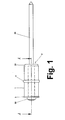
- La
figure 1 représente une vue générale d'un rivet élastique universel, selon l'invention, sur laquelle on peut en observer les composants, la structure et les particularités. - La
figure 2 représente une section générale exclusivement du corps élastique (1), selon l'indication A:A de la figure antérieure. - Les
figures 3a à 3d représentent, de façon schématique, différentes phases d'un assemblage élastique conformément à l'invention :-
Figures 3a : introduction du rivet élastique qui fait l'objet de l'invention dans les trous de foret des deux composants (Ci), (C2) à assembler. -
Figures 3b : début de la déformation du corps élastique (1), à la suite de la traction du corps de la tige, par exemple avec une riveteuse (R). -
Figure 3c : contraction et fixation élastiques des composants (Ci), (C2). -
Figure 3d : rupture du corps (20) de la tige (2) et assemblage élastique achevé.
-
- On décrit ci-dessous un exemple de réalisation pratique, non limitative, de la présente invention.
- L'objet de l'invention est un rivet élastique universel, constitué par un corps élastique (1), une tige (2) et une rondelle (3).
- Conformément à l'invention et selon la représentation représentée :
- le corps élastique (1) comporte un orifice (10) axial et comporte un bossage périmétral extérieur (11). Il s'agit de préférence d'un corps de révolution ;
- la tige (2) a une configuration oblongue et comporte à ses extrémités les têtes (21), (22), entre lesquelles est piacé le corps élastique (1), ces têtes venant se loger dans l'orifice axial (10) de ce corps élastique (1), au-delà duquel se prolonge son corps oblong (20) ;
- la rondelle (3) est disposée entre la tête (22) de la tige (2) et l'une des bases du corps élastique (1).
- Dans l'exemple de réalisation représenté sur la
figure 1 , plus concrètement, le rivet élastique de l'invention présente la particularité de se constituer à partir d'un corps élastique (1) de section circulaire, qui peut être cylindrique ou tronconique, comportant un orifice ou passage axial (10) où est montée une tige (2) rigide ou semi-rigide, ou un rivet conventionnel. - Cette tige (2) présente à l'une de ses extrémités une tête de butée (21) contre l'extrémité du corps élastique (1), alors que l'extrémité opposée est tronconique ou pointue et émerge à l'extérieur à travers l'autre extrémité dudit corps élastique (1), comptant à cette extrémité une rondelle de butée (3) rigide ou semi-rigide.
Le corps élastique (1), avec la tige-rivet (2) et la rondelle (3), forment un ensemble unique qui pénètre dans les orifices des matériaux (C1), (C2) à assembler; de manière à ce qu'au moyen d'un outil approprié, tel qu'une riveteuse (R), une traction soit exercée sur l'extrémité pointue (20) de la tige (2), en donnant lieu à son déplacement et, par conséquent, à la contraction du corps élastique (1) entre ladite tête de la tige et la rondelle (3), contraction qui entraîne l'expansion du corps flexible (1) et, par voie de conséquence, l'assemblage élastique des matériauxl (Ci), (C2).
Claims (3)
- Rivet élastique universel, caractérisé en ce que :a) il est consituté d'un corps élastique (1), d'une tige (2) et d'une rondelle (3) montés coaxialement ; ce corps élastique (1) étant disposé entre une tête (21) de la tige (2) et la rondelle (3)elle-même ;b) ce corps élastique (1) comporte un bossage périmétral extérieur (11) qui, lors du rivetage, demeure disposé entre les composants (C), (C2) à river, en évitant la transmission de vibrations et de bruits entre eux.
- Rivet élastique universel, selon la revendication 1, caractérisé en ce que la tige (2) est rigide ou semi-rigide.
- Rivet élastique universel, selon la revendication 1, caractérisé en ce que la tige (2) est un clou ou une fiche métallique.
Applications Claiming Priority (1)
| Application Number | Priority Date | Filing Date | Title |
|---|---|---|---|
| ES200800007A ES2323118B1 (es) | 2008-01-04 | 2008-01-04 | Remache elastico universal. |
Publications (2)
| Publication Number | Publication Date |
|---|---|
| EP2077397A2 true EP2077397A2 (fr) | 2009-07-08 |
| EP2077397A3 EP2077397A3 (fr) | 2010-11-24 |
Family
ID=40220062
Family Applications (2)
| Application Number | Title | Priority Date | Filing Date |
|---|---|---|---|
| EP08380130A Withdrawn EP2077397A3 (fr) | 2008-01-04 | 2008-04-30 | Rivet élastique universel |
| EP08870314A Withdrawn EP2241767A4 (fr) | 2008-01-04 | 2008-12-16 | Rivet élastique universel |
Family Applications After (1)
| Application Number | Title | Priority Date | Filing Date |
|---|---|---|---|
| EP08870314A Withdrawn EP2241767A4 (fr) | 2008-01-04 | 2008-12-16 | Rivet élastique universel |
Country Status (7)
| Country | Link |
|---|---|
| US (1) | US8459917B2 (fr) |
| EP (2) | EP2077397A3 (fr) |
| CN (1) | CN101960155A (fr) |
| BR (1) | BRPI0819954A2 (fr) |
| ES (1) | ES2323118B1 (fr) |
| MX (1) | MX2010007367A (fr) |
| WO (1) | WO2009087245A1 (fr) |
Citations (6)
| Publication number | Priority date | Publication date | Assignee | Title |
|---|---|---|---|---|
| ES273562A1 (es) | 1962-01-11 | 1962-07-16 | Ciba Geigy | Procedimiento para la preparaciën de hidrocarburos aromaticos que contienen isëtopos |
| ES290910A3 (es) | 1963-08-17 | 1964-03-01 | Ingbureauvan Elten N V | Un dispositivo para la fabricaciën de placas ligeras para construcciën |
| ES2228503T3 (es) | 1999-05-10 | 2005-04-16 | Trw Carr France | Elemento de union. |
| ES2247173T3 (es) | 2000-10-19 | 2006-03-01 | Textron Fastening Systems Limited | Union del tipo ciego. |
| ES2268139T3 (es) | 2001-12-14 | 2007-03-16 | Newfrey Llc | Remache ciego con estanqueidad. |
| ES2267470T3 (es) | 1999-12-07 | 2007-03-16 | Newfrey Llc | Remache ciego. |
Family Cites Families (21)
| Publication number | Priority date | Publication date | Assignee | Title |
|---|---|---|---|---|
| US2365372A (en) * | 1943-11-12 | 1944-12-19 | Gen Motors Corp | Hold-down attachment |
| US2893722A (en) * | 1957-09-06 | 1959-07-07 | Lord Mfg Co | Resilient mounting |
| US3017800A (en) * | 1958-08-15 | 1962-01-23 | Cohen Irvin | Anchor bolt with expanding sleeve |
| US3013643A (en) * | 1959-06-19 | 1961-12-19 | Goodrich Co B F | Fastener and cushioning structure utilizing the same |
| US3306053A (en) * | 1961-01-12 | 1967-02-28 | Fulton Samuel King | Marine facilities |
| US3534936A (en) * | 1968-07-31 | 1970-10-20 | United Carr Inc | Rotary operative vibration damping fastener |
| US3675881A (en) * | 1970-11-04 | 1972-07-11 | Huntington Rubber Mills | Bushing for vibration-isolating mounting |
| US3895408A (en) * | 1974-01-30 | 1975-07-22 | Charles J Leingang | Resilient mounting |
| US4189977A (en) * | 1978-01-06 | 1980-02-26 | H. K. Porter Company, Inc. | Weather tight blind fastener |
| DE7823094U1 (fr) * | 1978-08-02 | 1979-05-17 | Robert Bosch Gmbh, 7000 Stuttgart | |
| ES273562Y (es) | 1983-07-15 | 1984-07-01 | Lapafil - J. Pujol Rovira, S.A. | Remache monopieza de retencion por expansion |
| ES290910Y (es) | 1983-09-26 | 1986-12-01 | Sistemas De Fijacion Tucker,S.A. | Conjunto de remache ciego o sin sufridera |
| CH664801A5 (en) * | 1984-01-30 | 1988-03-31 | Georg Hirmann | Expansible plug for sealing hole - has friction layer around periphery to hold permanently in place |
| DE9001069U1 (de) * | 1990-01-31 | 1990-04-05 | Böllhoff & Co GmbH & Co KG, 4800 Bielefeld | Blindnietmutter |
| JP2504695Y2 (ja) * | 1990-10-12 | 1996-07-10 | 株式会社ニフコ | クリップ |
| GB9718733D0 (en) * | 1997-09-04 | 1997-11-12 | Mcalpine & Co Ltd | Anchoring device |
| JPH11287224A (ja) * | 1998-04-03 | 1999-10-19 | Togo Seisakusyo Corp | 防振クリップ |
| CN100504083C (zh) * | 2001-05-30 | 2009-06-24 | Pem管理股份有限公司 | 快速转动板紧固件 |
| US6905295B2 (en) * | 2003-07-22 | 2005-06-14 | General Motors Corporation | Blind rivet with extended adhesive reservoir |
| US7704160B2 (en) * | 2004-01-06 | 2010-04-27 | Balance-Certified Golf, Inc. | Apparatus for weighting golf club shaft |
| US20050238456A1 (en) * | 2004-04-26 | 2005-10-27 | Dennis Stinson | Fastener for the temporary joinder of parts made of composite material |
-
2008
- 2008-01-04 ES ES200800007A patent/ES2323118B1/es active Active
- 2008-04-30 EP EP08380130A patent/EP2077397A3/fr not_active Withdrawn
- 2008-12-16 BR BRPI0819954-0A patent/BRPI0819954A2/pt not_active Application Discontinuation
- 2008-12-16 US US12/811,811 patent/US8459917B2/en active Active
- 2008-12-16 WO PCT/ES2008/000782 patent/WO2009087245A1/fr not_active Ceased
- 2008-12-16 CN CN2008801278252A patent/CN101960155A/zh active Pending
- 2008-12-16 MX MX2010007367A patent/MX2010007367A/es unknown
- 2008-12-16 EP EP08870314A patent/EP2241767A4/fr not_active Withdrawn
Patent Citations (6)
| Publication number | Priority date | Publication date | Assignee | Title |
|---|---|---|---|---|
| ES273562A1 (es) | 1962-01-11 | 1962-07-16 | Ciba Geigy | Procedimiento para la preparaciën de hidrocarburos aromaticos que contienen isëtopos |
| ES290910A3 (es) | 1963-08-17 | 1964-03-01 | Ingbureauvan Elten N V | Un dispositivo para la fabricaciën de placas ligeras para construcciën |
| ES2228503T3 (es) | 1999-05-10 | 2005-04-16 | Trw Carr France | Elemento de union. |
| ES2267470T3 (es) | 1999-12-07 | 2007-03-16 | Newfrey Llc | Remache ciego. |
| ES2247173T3 (es) | 2000-10-19 | 2006-03-01 | Textron Fastening Systems Limited | Union del tipo ciego. |
| ES2268139T3 (es) | 2001-12-14 | 2007-03-16 | Newfrey Llc | Remache ciego con estanqueidad. |
Also Published As
| Publication number | Publication date |
|---|---|
| EP2077397A3 (fr) | 2010-11-24 |
| BRPI0819954A2 (pt) | 2015-06-16 |
| MX2010007367A (es) | 2010-09-30 |
| CN101960155A (zh) | 2011-01-26 |
| US8459917B2 (en) | 2013-06-11 |
| EP2241767A4 (fr) | 2012-11-14 |
| ES2323118B1 (es) | 2010-04-23 |
| WO2009087245A1 (fr) | 2009-07-16 |
| US20100278610A1 (en) | 2010-11-04 |
| ES2323118A1 (es) | 2009-07-06 |
| EP2241767A1 (fr) | 2010-10-20 |
Similar Documents
| Publication | Publication Date | Title |
|---|---|---|
| EP2007991B1 (fr) | Dispositif de serrage | |
| US9459466B2 (en) | Eyewear temple | |
| JP2013024423A (ja) | 回転防止機能を有する機能要素および該機能要素とシート金属部材とを備える部品アセンブリ | |
| FR2877150A1 (fr) | Procede de montage d'un connecteur electrique sur un cable coaxial, et un tel connecteur | |
| FR2950662A1 (fr) | Dispositif de fixation d'un element de forme allongee sur un carter de turbomachine | |
| EP3001240A1 (fr) | Branche de lunettes | |
| EP2878031B1 (fr) | Système de fixation d'une pile thermique dans une section d'alimentation d'un engin sous marin | |
| EP3095684B1 (fr) | Patte de derailleur | |
| FR3040131A1 (fr) | Dispositif a ouverture rapide par pression unique d'un couvercle de toilette | |
| US10488043B2 (en) | Arc lighter fixing element | |
| EP2430321B1 (fr) | Dispositif pour fixer une premiere piece sur une deuxieme piece qui est elle-meme fixee sur une troisieme piece, assemblage de trois pieces en particulier d'un vehicule automobile | |
| EP2077397A2 (fr) | Rivet élastique universel | |
| EP0536005A1 (fr) | Dispositif pour l'assemblage et le désassemblage rapide de deux pièces l'une sur l'autre | |
| FR3051854A1 (fr) | Carter d'echappement de turbomachine | |
| EP1813826B1 (fr) | Dispositif de liaison amovible comportant une agrafe de verrouillage | |
| FR2984237A1 (fr) | Dispositif de fixation d'un chassis rapporte sur la caisse d'un vehicule, en particulier d'un chassis de chaine de traction sur la caisse d'un vehicule automobile electrique | |
| CN106286528B (zh) | 一种高防松旋铆型抽芯铆钉 | |
| FR2961119A1 (fr) | Methode d'evaluation de la qualite du rivetage des assemblages rivetes et dispositif de mise en œuvre | |
| FR2473961A1 (fr) | Suspension de | |
| FR2493443A1 (fr) | Amortisseur tubulaire a friction | |
| FR2945983A1 (fr) | Butee de suspension et vehicule comportant une butee de suspension | |
| JP2017031621A (ja) | 保孔管の引抜き防止具及びそれを用いた保孔管の設置工法 | |
| FR2760989A1 (fr) | Appareil de montage automatique de demi-mors sur une soupape | |
| EP2971837B1 (fr) | Frein à tambour comportant un cylindre de roue avec une surface d'appui réduite sur le plateau et avec interposition d'un élément de guidage entre le cylindre et le plateau | |
| CN209838862U (zh) | 一种防脱落且便于拆卸的卡箍连接结构 |
Legal Events
| Date | Code | Title | Description |
|---|---|---|---|
| PUAI | Public reference made under article 153(3) epc to a published international application that has entered the european phase |
Free format text: ORIGINAL CODE: 0009012 |
|
| AK | Designated contracting states |
Kind code of ref document: A2 Designated state(s): AT BE BG CH CY CZ DE DK EE ES FI FR GB GR HR HU IE IS IT LI LT LU LV MC MT NL NO PL PT RO SE SI SK TR |
|
| AX | Request for extension of the european patent |
Extension state: AL BA MK RS |
|
| PUAL | Search report despatched |
Free format text: ORIGINAL CODE: 0009013 |
|
| AK | Designated contracting states |
Kind code of ref document: A3 Designated state(s): AT BE BG CH CY CZ DE DK EE ES FI FR GB GR HR HU IE IS IT LI LT LU LV MC MT NL NO PL PT RO SE SI SK TR |
|
| AX | Request for extension of the european patent |
Extension state: AL BA MK RS |
|
| REG | Reference to a national code |
Ref country code: DE Ref legal event code: R108 |
|
| AKY | No designation fees paid | ||
| REG | Reference to a national code |
Ref country code: DE Ref legal event code: R108 Effective date: 20110720 |
|
| STAA | Information on the status of an ep patent application or granted ep patent |
Free format text: STATUS: THE APPLICATION IS DEEMED TO BE WITHDRAWN |
|
| 18D | Application deemed to be withdrawn |
Effective date: 20110525 |