EP2077452A1 - Cassette de réactifs - Google Patents
Cassette de réactifs Download PDFInfo
- Publication number
- EP2077452A1 EP2077452A1 EP08100167A EP08100167A EP2077452A1 EP 2077452 A1 EP2077452 A1 EP 2077452A1 EP 08100167 A EP08100167 A EP 08100167A EP 08100167 A EP08100167 A EP 08100167A EP 2077452 A1 EP2077452 A1 EP 2077452A1
- Authority
- EP
- European Patent Office
- Prior art keywords
- valve
- reagent
- bag
- liquid
- analyzer
- Prior art date
- Legal status (The legal status is an assumption and is not a legal conclusion. Google has not performed a legal analysis and makes no representation as to the accuracy of the status listed.)
- Granted
Links
Images


Classifications
-
- G—PHYSICS
- G01—MEASURING; TESTING
- G01N—INVESTIGATING OR ANALYSING MATERIALS BY DETERMINING THEIR CHEMICAL OR PHYSICAL PROPERTIES
- G01N35/00—Automatic analysis not limited to methods or materials provided for in any single one of groups G01N1/00 - G01N33/00; Handling materials therefor
- G01N35/10—Devices for transferring samples or any liquids to, in, or from, the analysis apparatus, e.g. suction devices, injection devices
- G01N35/1002—Reagent dispensers
-
- B—PERFORMING OPERATIONS; TRANSPORTING
- B01—PHYSICAL OR CHEMICAL PROCESSES OR APPARATUS IN GENERAL
- B01L—CHEMICAL OR PHYSICAL LABORATORY APPARATUS FOR GENERAL USE
- B01L3/00—Containers or dishes for laboratory use, e.g. laboratory glassware; Droppers
- B01L3/50—Containers for the purpose of retaining a material to be analysed, e.g. test tubes
- B01L3/502—Containers for the purpose of retaining a material to be analysed, e.g. test tubes with fluid transport, e.g. in multi-compartment structures
-
- B—PERFORMING OPERATIONS; TRANSPORTING
- B01—PHYSICAL OR CHEMICAL PROCESSES OR APPARATUS IN GENERAL
- B01L—CHEMICAL OR PHYSICAL LABORATORY APPARATUS FOR GENERAL USE
- B01L2200/00—Solutions for specific problems relating to chemical or physical laboratory apparatus
- B01L2200/16—Reagents, handling or storing thereof
-
- B—PERFORMING OPERATIONS; TRANSPORTING
- B01—PHYSICAL OR CHEMICAL PROCESSES OR APPARATUS IN GENERAL
- B01L—CHEMICAL OR PHYSICAL LABORATORY APPARATUS FOR GENERAL USE
- B01L2300/00—Additional constructional details
- B01L2300/06—Auxiliary integrated devices, integrated components
- B01L2300/0627—Sensor or part of a sensor is integrated
- B01L2300/0663—Whole sensors
-
- B—PERFORMING OPERATIONS; TRANSPORTING
- B01—PHYSICAL OR CHEMICAL PROCESSES OR APPARATUS IN GENERAL
- B01L—CHEMICAL OR PHYSICAL LABORATORY APPARATUS FOR GENERAL USE
- B01L2300/00—Additional constructional details
- B01L2300/08—Geometry, shape and general structure
- B01L2300/0809—Geometry, shape and general structure rectangular shaped
- B01L2300/0816—Cards, e.g. flat sample carriers usually with flow in two horizontal directions
-
- B—PERFORMING OPERATIONS; TRANSPORTING
- B01—PHYSICAL OR CHEMICAL PROCESSES OR APPARATUS IN GENERAL
- B01L—CHEMICAL OR PHYSICAL LABORATORY APPARATUS FOR GENERAL USE
- B01L2300/00—Additional constructional details
- B01L2300/08—Geometry, shape and general structure
- B01L2300/0861—Configuration of multiple channels and/or chambers in a single devices
- B01L2300/0867—Multiple inlets and one sample wells, e.g. mixing, dilution
-
- B—PERFORMING OPERATIONS; TRANSPORTING
- B01—PHYSICAL OR CHEMICAL PROCESSES OR APPARATUS IN GENERAL
- B01L—CHEMICAL OR PHYSICAL LABORATORY APPARATUS FOR GENERAL USE
- B01L2400/00—Moving or stopping fluids
- B01L2400/04—Moving fluids with specific forces or mechanical means
- B01L2400/0475—Moving fluids with specific forces or mechanical means specific mechanical means and fluid pressure
- B01L2400/0487—Moving fluids with specific forces or mechanical means specific mechanical means and fluid pressure fluid pressure, pneumatics
-
- B—PERFORMING OPERATIONS; TRANSPORTING
- B01—PHYSICAL OR CHEMICAL PROCESSES OR APPARATUS IN GENERAL
- B01L—CHEMICAL OR PHYSICAL LABORATORY APPARATUS FOR GENERAL USE
- B01L2400/00—Moving or stopping fluids
- B01L2400/06—Valves, specific forms thereof
- B01L2400/0633—Valves, specific forms thereof with moving parts
- B01L2400/0644—Valves, specific forms thereof with moving parts rotary valves
-
- Y—GENERAL TAGGING OF NEW TECHNOLOGICAL DEVELOPMENTS; GENERAL TAGGING OF CROSS-SECTIONAL TECHNOLOGIES SPANNING OVER SEVERAL SECTIONS OF THE IPC; TECHNICAL SUBJECTS COVERED BY FORMER USPC CROSS-REFERENCE ART COLLECTIONS [XRACs] AND DIGESTS
- Y10—TECHNICAL SUBJECTS COVERED BY FORMER USPC
- Y10T—TECHNICAL SUBJECTS COVERED BY FORMER US CLASSIFICATION
- Y10T436/00—Chemistry: analytical and immunological testing
- Y10T436/25—Chemistry: analytical and immunological testing including sample preparation
Definitions
- the invention relates to a reagent cartridge, which can be used interchangeably in an analyzer and has a plurality of reagent bags, wherein the reagent bags are equipped with connecting lines, which can be optionally connected to an input device of the analyzer. Furthermore, the invention relates to a reagent bag with a valve arranged in the connecting line and to a method for operating an analyzer which has a measuring chamber and an exchangeable reagent cassette.
- the analyzer can be used, for example, as a portable analyzer for the determination of POC (Point Of Care) parameters, namely the blood gases (O 2 , CO 2 , pH), the electrolytes (K + , Na + , Ca ++ , Cl - ) of the metabolites ( Glucose and lactate), hematocrit, hemoglobin parameters (tHb, SO 2 , etc.) and bilirubin, which is used for the decentralized determination of said parameters in whole blood samples.
- POC Point Of Care
- the problem involves connecting a plurality of reagent bags to the analyzer, all liquids, i. Both the originating from different sampling sample (eg blood), any external quality control fluids (QC fluids) and present in the reagent bags a reagent cartridge functional fluids, such as calibration, QC rinsing, disinfecting and cleaning fluids, preferably via a single input element (eg input needle) to be sucked into the analyzer.
- QC fluids quality control fluids
- the partially tonometrized functional fluids are filled in reagent pouches (e.g., aluminum laminated laminated pouches).
- reagent pouches e.g., aluminum laminated laminated pouches.
- the reagent bags are sealed in known arrangements before use in the analyzer each with a septum or a valve (bag valve), which is irreversibly opened when inserted into the analyzer and their content is released for removal.
- an analytical device for measuring liquid or gaseous samples in which the input element (eg a hollow needle) of the sample input device in the basic position seals the analysis path against a docking element, which is provided with hose lines for supplying the calibration or standard media, as well as a valve-controlled Connection for supplying air communicates.
- a docking element which is provided with hose lines for supplying the calibration or standard media, as well as a valve-controlled Connection for supplying air communicates.
- sample liquids can be supplied from different sampling vessels.
- the shut-off valves of the analyzer arranged separately replaceable reagent containers are designed as simple shut-off valves.
- a similar embodiment of an analyzer discloses the US 4,499,053 A ,
- the US 5,882,602 A discloses, for example, a "self-sealing-valve", in combination with a "flow fitting". This is an elastomeric septum in the reagent bag connector that is punctured by a needle when inserted into the analyzer. The same applies to a bag connection, which in the US 5,780,302 A is described.
- Fig. 1 of the US 6,872,297 B2 shows a replaceable reagent cartridge (Disposable Cartridge), which has a plurality of reagent bags with calibration and washing liquids (A, B, Rinse), the connecting lines are fed via a rotary valve and a manifold of the pivoting cannula of an input unit. From there, get the fluids then via another line into the measuring chamber and finally via a peristaltic pump into the waste container, which is also arranged in the reagent cassette. Via the rotary valve, air can also be fed into the collecting line in a rotational position.
- Disposable Cartridge Disposable Cartridge
- A, B, Rinse calibration and washing liquids
- connection lines leading from the reagent bags to the rotary valve can not be emptied without risking contamination of the bag contents with air.
- the calibration or quality control fluids contained in the reagent cartridge must be removed from the respective reagent bags via a hose line system and a manifold (see eg DE 35 02 546 C2 ) or rotary valve (see eg US 6,872,297 A ) are transported contamination-free via a hollow needle into the measuring cell.
- gas permeability of the tubing in the supply lines causes significant changes in the calibration or quality control gas concentrations. Liquids.
- the object of the invention is to improve a usable in an analyzer reagent cartridge with reagent bags of the type described above, so that the gas permeability of the tubing in the connecting lines or the backflow of already removed functional fluids no adverse effects on the gas concentrations of Kalibrations- or quality control Caused fluids.
- the operation of the analyzer should be as simple, inexpensive, robust and maintenance-free to accomplish.
- each reagent bag directly at the confluence of the respective connecting line has a multi-directional valve controllable by the analyzer with at least two valve positions, wherein the first valve position establishes a fluid connection between the connecting line and the reagent bag and the second valve position closes the reagent bag and establishes a fluid connection between a ventilation source, preferably the ambient air, and the connection line.
- a ventilation source preferably the ambient air
- connection lines of the reagent bags leading away from the multiway valves open directly into a common bus line connected upstream of the input device of the analyzer.
- a common rail By using a common rail, a valveless connection to the input device of the analyzer can be produced, which, in combination with the multi-way valves integrated in the individual reagent bags, leads to the advantages of the invention described in detail below.
- the leads leading away from the multiway valves open directly into a collection valve connected upstream of the input device, preferably a rotary valve.
- each multi-way valve has a third valve position, in which both the access to the reagent bag and the fluid connection to the ventilation source are closed. This ensures that the connection lines are not contaminated by environmental contaminants during storage or transport of the reagent cassettes or during long measuring breaks.
- each multi-way valve of the reagent bag is designed as a piston valve having a first port which is welded or glued into an edge seam of the reagent bag, and a second port which is connected to a connecting line, wherein in the valve housing of the piston valve a Valve piston is axially displaceably guided, which has a sealing region between a first and a second overflow region, which areas can be brought by a displacement of the valve piston selectively with the second port to cover.
- Each valve piston in this case has an engagement opening for the engagement of an analyzer side arranged actuating element, wherein the actuating elements of the individual bag valves automatically engage when inserting the reagent cartridge into the analyzer.
- a reagent cartridge 2 which is exchangeable inserted into the analyzer 1.
- a plurality of reagent bags A to D are arranged, which contain functional fluids such as calibrants, quality control agents, rinsing, disinfecting and washing solutions, which can optionally be supplied to an input device 3 and subsequently a measuring chamber 5 arranged, for example, in a sensor cassette 4
- the input device 3 of the analyzer 1 has a pivotable input element 13 (for example a hollow needle), which is in a basic position with a docking element 14 for the supply of calibration and detergent in combination, wherein in a pivoted from the basic position position 15 sample liquids can be supplied ,
- the sample input can be made from different vessels (eg syringe, capillary tube, glass vessel, etc.) preferably via a movable, for example pivotable, input element, as described for example in US Pat DE 35 02 546 C2 and the US 4,499,053 A is described.
- vessels eg syringe, capillary tube, glass vessel, etc.
- a movable, for example pivotable, input element as described for example in US Pat DE 35 02 546 C2 and the US 4,499,053 A is described.
- Each reagent bag A to D has directly at the junction of the respective connecting line 6, 7, 8, 9 a controllable by the analyzer multi-way valve 10 (bag valve) with at least two valve positions, wherein the first valve position, a fluid connection between the respective connecting line 6, 7, 8 , 9 and the associated reagent bag A to D.
- the second valve position the respective reagent bag A to D is closed and a fluid connection 11 (see, eg Fig. 2 to Fig. 4 ) between a ventilation source, preferably the ambient air and the connecting line 6, 7, 8, 9 made.
- connection lines 6 to 9 of the bag valves 10 are made of flexible plastic tubing, for example.
- the sample input device 3 with the pivotable input element 13 is preferably an integral part of the reagent cassette 2 and is exchanged therewith.
- the fluid line leads to the sensor cassette 4 via the fixed part of a built-in analyzer 1 peristaltic pump 29 and opens into a disposed in the reagent cartridge 2 waste bag 30.
- the sensor cartridge 4 is not in the illustrated embodiment in the reagent cartridge 2 and can be replaced independently of this become.
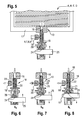
- Each multi-way valve 10 (bag valve) is designed in each case as a piston valve, which has a first connection 16, which in an edge seam 17 (see Fig. 4 ) of the reagent bag A, B and C is welded or glued. Furthermore, each piston valve 10 has a hose connection 18, which is connected to a connecting line 6, 7, 8.
- a valve piston 20 is guided axially displaceable, which has a sealing region 22 between a first 21 and a second overflow region 23, which areas 21, 22, 23 are brought by a displacement of the valve piston 20 with the hose connection 18 to cover can.
- valve position SK the reagent can be sucked out of the bag C via the overflow region 23.
- second valve position SL the bag A is closed, wherein air can be sucked in via the overflow opening 21 in the piston 20 and the fluid connection 11.
- both the bag connection 16 and the fluid connection 11 are closed by the sealing region 22.
- the individual valve positions are based on a specific embodiment in detail in the Fig. 6 to Fig. 8 shown.
- FIG. 3 shows a variant of the invention, in which the multi-way valves are each designed as rotary valves 10 ', which in a first rotational position SK fluid communication between the connecting lines 6, 7, 8 and the reagent bags A, B, C and in a second rotational position SL fluid communication 11 between a ventilation source, preferably the ambient air, and the connecting lines 6, 7, 8 produce.
- a ventilation source preferably the ambient air
- the connecting lines 6, 7, 8 open directly and valveless into the manifold 12 (common rail) and can be sucked completely liquid-free and dry without contaminating the bag contents.
- both the bag connection 16 and the fluid connection 11 are closed by the rotary valve 10 '.
- Fig. 5 shown - the system coupling of the reagent bag A to D to the bag connection (first port) 16 preferably realized as a butterfly connection and incorporated therein a piston valve 10.
- the butterflies also called shuttles
- the butterflies can preferably be welded or glued into an edge or side seam 17 of the pouches.
- a reagent bag A, B, C, D according to the invention with a valve 10 arranged at the junction of a connection line 6, 7, 8, 9, which has a first valve position (open position) and a second valve position (closed position), is thus characterized in that that in the closed position, a fluid connection 11 between a ventilation source, preferably the ambient air, and the connecting line 6, 7, 8, 9 is made (see Fig. 8 ).
- the valve piston 20 has an engagement opening 24 for the engagement of an analyzer side arranged actuating element 25, which is for switching to the individual valve positions - as indicated by arrows - moved up and down.
- the sealing region 22 of the valve piston 20 can be delimited by the two adjacent overflow regions 21, 23 in each case by an O-ring seal 26.
- connection lines 6 to 9 are liquid-free.
- Example 1 Generation of a liquid packet from the reagent bag A for measurement in the measuring chamber.
- step 1 a basic state (step 1) is assumed in which the fluid connections from the respective bag valve 10 to the measuring chamber 5 are filled with air. All bag valves 10 are in position SG, the peristaltic pump 29 is deactivated and the input unit 13 is located in the docking element 14 (pos.W).
- Table 1 step Valve position for bag A Valve position with bag BD Position input unit 13 action 1 SG SG posw standby 2 SG> SK SG posw Valve at A in position SK 3 SK SG posw
- pump liquid is sucked from the bag A via manifold 12 and docking member 14 to and into or through the measuring chamber 5.
- the packet size i. the quantity or the volume of the liquid from the reagent bag A can be set in a time-controlled manner or by means of a response of monitoring sensors in the event of liquid contact, which are positioned in the path to the measuring chamber 5.
- step 1 upstream steps provided.
- steps 1 to 8 downstream are optional here not detailed running.
- Example 2 Washing and Preparation for Positioning a Sample in the Measuring Chamber
- the multi-way valve of at least one reagent bag which preferably contains a cleaning, disinfecting or rinsing liquid, alternating from the first valve position (SK) for sucking liquid in the second valve position (SL) for sucking a gaseous medium, preferably ambient air , switched so that alternately liquid and gas separation packages are formed and transported through the line system of the analyzer to the measuring chamber. It has been shown that washing, in particular of the measuring chamber, by alternating flushing with liquid and air separation packets is particularly advantageous.
- step 1 a basic state (step 1) is assumed in which the fluid connections from the respective bag valve 10 to the measuring chamber 5 are filled with air. All bag valves 10 are in position SG, the pump 29 is deactivated and the input unit 13 is located in the docking element 14 (pos.W).
- Table 2 step Valve position for bag A Valve position for bag B Valve position with bag CD action 1 SG SG SG standby 2 SG ⁇ SK SG SG Valve at A in position SK 3 SK SG SG
- pump liquid is sucked from the bag A via manifold 12 and docking member 14 to the measuring chamber 5 4 SK ⁇ SG SG ⁇ SL SG
- the valves at A and B are synchronized.
- any number of liquid and gas separation packages e.g., air separation packages
- any number of liquid and gas separation packages e.g., air separation packages
- Example 3 Partially fill connection lines 6 to 9 of the reagent bags A to D with liquid
- the pressure in the gas-carrying connection lines of the reagent bags preferably by a brief increase in the speed of a provided for liquid transport in the analyzer peristaltic pump, first lowered and then increased again, preferably by lowering the speed the hose pump 29 to normal operation, so that liquid is introduced into parts of the connecting lines 6, 7, 8, 9, which open into a common manifold 12.
- connection lines 7 to 9 are partially filled with liquid at the connection point to the manifold 12.
- the basis for this is the short-term increase in the suction speed of the pump 29 and the associated negative pressure in the connecting lines 7 to 9. If the suction speed of the pump 29 is lowered back to the normal rate, there is a contraction of the gas volumes in the connecting lines 7 to 9, these are partially filled with liquid from the manifold 12.
- step 1 a basic state (step 1) is assumed, which has already been described in Example 1.
- Table 3 step Valve position for bag A Valve position for bag B Valve position with bag CD action 1 SG SG SG standby 2 SG ⁇ SK SG SG Valve at A in position SK 3 SK SG SG
- the suction speed of the pump 29 is increased briefly, so that there is an increased suction rate of liquid A.
- Example 4 Use of a collecting valve (reusable valve) instead of a collecting line
- the sequence shown in Table 4 shows an example that instead of the manifold 12 and a collection valve, such as a rotary valve 27 can be used.
- the rotary valve 27 has, for example, the positions 27-6, 27-7, and 27-8 (which in each case the connection to the connecting lines 6, 7 and 8 according to Fig. 4 , is indicated).
Landscapes
- Health & Medical Sciences (AREA)
- Chemical & Material Sciences (AREA)
- Analytical Chemistry (AREA)
- General Health & Medical Sciences (AREA)
- Immunology (AREA)
- Biochemistry (AREA)
- Life Sciences & Earth Sciences (AREA)
- General Physics & Mathematics (AREA)
- Physics & Mathematics (AREA)
- Pathology (AREA)
- Hematology (AREA)
- Clinical Laboratory Science (AREA)
- Chemical Kinetics & Catalysis (AREA)
- Sampling And Sample Adjustment (AREA)
- Automatic Analysis And Handling Materials Therefor (AREA)
- Steroid Compounds (AREA)
Priority Applications (9)
| Application Number | Priority Date | Filing Date | Title |
|---|---|---|---|
| EP08100167A EP2077452B1 (fr) | 2008-01-07 | 2008-01-07 | Cassette de réactifs |
| AT08100167T ATE489636T1 (de) | 2008-01-07 | 2008-01-07 | Reagenzienkassette |
| ES08100167T ES2354850T3 (es) | 2008-01-07 | 2008-01-07 | Casete de reactivos. |
| DE502008001880T DE502008001880D1 (de) | 2008-01-07 | 2008-01-07 | Reagenzienkassette |
| CA2647831A CA2647831C (fr) | 2008-01-07 | 2008-12-23 | Cartouche a reactif |
| JP2009000525A JP5172716B2 (ja) | 2008-01-07 | 2009-01-06 | 試薬カートリッジ |
| CN2009100013231A CN101482571B (zh) | 2008-01-07 | 2009-01-07 | 试剂盒 |
| US12/349,685 US9075033B2 (en) | 2008-01-07 | 2009-01-07 | Reagent cartridge |
| HK09108339.4A HK1130314B (en) | 2008-01-07 | 2009-09-11 | A reagent cartridge |
Applications Claiming Priority (1)
| Application Number | Priority Date | Filing Date | Title |
|---|---|---|---|
| EP08100167A EP2077452B1 (fr) | 2008-01-07 | 2008-01-07 | Cassette de réactifs |
Publications (2)
| Publication Number | Publication Date |
|---|---|
| EP2077452A1 true EP2077452A1 (fr) | 2009-07-08 |
| EP2077452B1 EP2077452B1 (fr) | 2010-11-24 |
Family
ID=39292655
Family Applications (1)
| Application Number | Title | Priority Date | Filing Date |
|---|---|---|---|
| EP08100167A Active EP2077452B1 (fr) | 2008-01-07 | 2008-01-07 | Cassette de réactifs |
Country Status (8)
| Country | Link |
|---|---|
| US (1) | US9075033B2 (fr) |
| EP (1) | EP2077452B1 (fr) |
| JP (1) | JP5172716B2 (fr) |
| CN (1) | CN101482571B (fr) |
| AT (1) | ATE489636T1 (fr) |
| CA (1) | CA2647831C (fr) |
| DE (1) | DE502008001880D1 (fr) |
| ES (1) | ES2354850T3 (fr) |
Cited By (2)
| Publication number | Priority date | Publication date | Assignee | Title |
|---|---|---|---|---|
| EP2409766A1 (fr) | 2010-07-23 | 2012-01-25 | F. Hoffmann-La Roche AG | Procédé d'hydrophilisation de surfaces de composants fluidiques et composants contenant de tels composants |
| EP3222996A1 (fr) * | 2016-03-21 | 2017-09-27 | Tintometer GmbH | Ensemble de suspension d'etalonnage, procede de fabrication d'un ensemble de suspension d'etalonnage et utilisation d'un ensemble de suspension d'etalonnage |
Families Citing this family (28)
| Publication number | Priority date | Publication date | Assignee | Title |
|---|---|---|---|---|
| WO2010069960A1 (fr) * | 2008-12-19 | 2010-06-24 | F. Hoffmann-La Roche Ag | Dispositif et procédé pour l'exécution automatique d'une vérification de l'étalonnage d'un analyseur |
| DE102009029305A1 (de) * | 2009-09-09 | 2011-03-10 | Endress + Hauser Conducta Gesellschaft für Mess- und Regeltechnik mbH + Co. KG | Analysegerät zur automatisierten Bestimmung einer Messgröße einer Flüssigkeitsprobe |
| EP2466316B1 (fr) * | 2010-12-15 | 2015-11-25 | F.Hoffmann-La Roche Ag | Systèmes fluidiques, conteneur de fluide et procédés de lavage de conduits de fluide |
| US8988684B1 (en) | 2011-09-08 | 2015-03-24 | Lawrence Livermore National Security, Llc | System and method for measuring fluorescence of a sample |
| US9372135B1 (en) * | 2011-09-08 | 2016-06-21 | Lawrence Livermore National Security, Llc | Fluidics platform and method for sample preparation |
| DK2825309T3 (en) | 2012-03-16 | 2018-07-30 | Stat Diagnostica & Innovation Sl | Sample cartridge with integrated transfer module |
| DE102012102256B4 (de) * | 2012-03-16 | 2024-05-29 | Endress+Hauser Conducta Gmbh+Co. Kg | Analysegerät mit Basismodul und austauschbarer Kassette |
| DE102012205171B3 (de) * | 2012-03-29 | 2013-09-12 | Fraunhofer-Gesellschaft zur Förderung der angewandten Forschung e.V. | Integriertes Einweg-Chipkartuschensystem für mobile Multiparameteranalysen chemischer und/oder biologischer Substanzen |
| ES2666795T3 (es) * | 2012-05-08 | 2018-05-07 | Roche Diagniostics Gmbh | Cartucho para dispensar un fluido |
| EP2669677B1 (fr) * | 2012-05-31 | 2018-09-12 | F. Hoffmann-La Roche AG | Procédé et dispositif d'accélération de l'équilibrage d'un liquide |
| NL2017959B1 (en) * | 2016-12-08 | 2018-06-19 | Illumina Inc | Cartridge assembly |
| WO2016130964A1 (fr) | 2015-02-13 | 2016-08-18 | Abbott Laboratories | Appareils, systèmes et procédés de débouchage et de bouchage pouvant être utilisés dans des analyseurs à visée diagnostique |
| EP3098606A1 (fr) * | 2015-05-29 | 2016-11-30 | Roche Diagniostics GmbH | Cartouche permettant de distribuer des particules et un fluide reactif |
| US20190021702A1 (en) * | 2015-08-31 | 2019-01-24 | Eon Medica S.R.L. | Extraction and analysis device, in particular for synovial fluid |
| JP6610377B2 (ja) * | 2016-03-28 | 2019-11-27 | 東亜ディーケーケー株式会社 | 試薬供給ユニット、試薬供給装置、及び分析システム |
| CN106483277A (zh) * | 2016-03-31 | 2017-03-08 | 广州万孚生物技术股份有限公司 | 血气生化试剂包 |
| CN106483179A (zh) * | 2016-03-31 | 2017-03-08 | 广州万孚生物技术股份有限公司 | 血气分析仪及其血气生化测试卡 |
| CN118067818B (zh) * | 2016-03-31 | 2026-02-17 | 深圳市理邦精密仪器股份有限公司 | 试剂包组件及血气分析仪 |
| MY194951A (en) | 2016-10-14 | 2022-12-28 | Illumina Inc | Cartridge assembly |
| EP3647781B1 (fr) | 2018-10-29 | 2024-05-01 | EXIAS Medical GmbH | Cartouche de mesure d'un échantillon liquide |
| US12005437B2 (en) | 2019-05-28 | 2024-06-11 | Illumina, Inc. | Two-phase flushing systems and methods |
| WO2021097188A1 (fr) * | 2019-11-15 | 2021-05-20 | Sundance Spas, Inc. | Systèmes et dispositifs d'analyse d'eau |
| EP4084904A4 (fr) * | 2019-12-30 | 2024-05-29 | Illumina, Inc. | Ensembles cuve à circulation t et vannes de sélection de réactifs associées |
| CN112903984B (zh) * | 2021-01-18 | 2022-04-22 | 江西英大生物技术有限公司 | 涎液化糖链抗原6检测的试剂盒、适配的检测装置及检测方法 |
| WO2025228687A1 (fr) | 2024-04-30 | 2025-11-06 | Roche Diagnostics International Ag | Bloc de fluide pouvant être accueilli dans un analyseur ivd |
| WO2025245755A1 (fr) * | 2024-05-29 | 2025-12-04 | 深圳市理邦精密仪器股份有限公司 | Kit pour analyseur de gaz sanguin et analyseur de gaz sanguin |
| WO2025245758A1 (fr) * | 2024-05-29 | 2025-12-04 | 深圳市理邦精密仪器股份有限公司 | Analyseur de gaz sanguin et kit pour analyseur de gaz sanguin |
| WO2025245754A1 (fr) * | 2024-05-29 | 2025-12-04 | 深圳市理邦精密仪器股份有限公司 | Kit pour analyseur des gaz du sang et analyseur des gaz du sang |
Citations (8)
| Publication number | Priority date | Publication date | Assignee | Title |
|---|---|---|---|---|
| US3929413A (en) * | 1974-03-04 | 1975-12-30 | Anatronics Corp | Fluid transport and metering system |
| US4499053A (en) | 1982-06-10 | 1985-02-12 | Instrumentation Laboratory Inc. | Fluid sampling |
| DE3502546C2 (de) | 1984-02-02 | 1986-01-02 | AVL AG, Schaffhausen | Analysengerät zur Messung flüssiger oder gasförmiger Proben |
| US5780302A (en) | 1995-11-02 | 1998-07-14 | Chiron Diagnostics Corporation | Method of packaging oxygen reference solution using flexile package with inside valve |
| US5882602A (en) | 1996-05-20 | 1999-03-16 | Sendx Medical, Inc. | Integral fluid and waste container for blood analyzer |
| WO2002097414A2 (fr) * | 2001-05-31 | 2002-12-05 | Instrumentation Laboratory Company | Appareils d'analyse, biocapteurs et methodes associees |
| US20040047771A1 (en) * | 1995-11-02 | 2004-03-11 | Conlon Dennis R. | Multi-analyte reference solutions with stable pO2 in zero headspace containers |
| EP1495809A1 (fr) * | 2003-07-08 | 2005-01-12 | Fresenius Medical Care Deutschland GmbH | Cassette jetable avec un récipient intégré ouvrable avec une aiguille |
Family Cites Families (11)
| Publication number | Priority date | Publication date | Assignee | Title |
|---|---|---|---|---|
| US2938351A (en) * | 1959-05-14 | 1960-05-31 | Bickerstaff Inc | Fluid pressure balancing valve |
| US3929414A (en) * | 1974-01-21 | 1975-12-30 | Baxter Laboratories Inc | Blood oxygenator utilizing a removable membrane oxygenator unit |
| JPS5870079A (ja) * | 1981-10-23 | 1983-04-26 | Pilot Pen Co Ltd:The | ぜん動ポンプ |
| JPS60176174U (ja) * | 1984-04-28 | 1985-11-21 | 株式会社島津製作所 | 分析機器 |
| US5140845A (en) * | 1989-12-01 | 1992-08-25 | University Of Connecticut | Method for measuring volatile constituents in earth samples |
| US5422079A (en) | 1990-06-21 | 1995-06-06 | Oxford Glycosystems Limited | Automated process equipment |
| US5279797A (en) * | 1992-10-05 | 1994-01-18 | Avl Scientific Corporation | Disposable liquid reagent cartridge and receptacle therefor |
| FR2723735B1 (fr) | 1994-08-18 | 1996-10-31 | Abx Sa | Boitier a branchement automatique pour distribution de reactifs dans un appareil notamment un analyseur hematologique. |
| CN2502273Y (zh) * | 2001-11-23 | 2002-07-24 | 北京吉大小天鹅仪器有限公司 | 用于原子荧光光谱仪的顺序注射进样装置 |
| GB0424660D0 (en) * | 2004-11-08 | 2004-12-08 | Randox Lab Ltd | Reagent holding bag |
| JP4553195B2 (ja) * | 2005-02-15 | 2010-09-29 | 理研計器株式会社 | ガス測定装置 |
-
2008
- 2008-01-07 AT AT08100167T patent/ATE489636T1/de active
- 2008-01-07 DE DE502008001880T patent/DE502008001880D1/de active Active
- 2008-01-07 ES ES08100167T patent/ES2354850T3/es active Active
- 2008-01-07 EP EP08100167A patent/EP2077452B1/fr active Active
- 2008-12-23 CA CA2647831A patent/CA2647831C/fr not_active Expired - Fee Related
-
2009
- 2009-01-06 JP JP2009000525A patent/JP5172716B2/ja not_active Expired - Fee Related
- 2009-01-07 US US12/349,685 patent/US9075033B2/en active Active
- 2009-01-07 CN CN2009100013231A patent/CN101482571B/zh not_active Expired - Fee Related
Patent Citations (9)
| Publication number | Priority date | Publication date | Assignee | Title |
|---|---|---|---|---|
| US3929413A (en) * | 1974-03-04 | 1975-12-30 | Anatronics Corp | Fluid transport and metering system |
| US4499053A (en) | 1982-06-10 | 1985-02-12 | Instrumentation Laboratory Inc. | Fluid sampling |
| DE3502546C2 (de) | 1984-02-02 | 1986-01-02 | AVL AG, Schaffhausen | Analysengerät zur Messung flüssiger oder gasförmiger Proben |
| US5780302A (en) | 1995-11-02 | 1998-07-14 | Chiron Diagnostics Corporation | Method of packaging oxygen reference solution using flexile package with inside valve |
| US20040047771A1 (en) * | 1995-11-02 | 2004-03-11 | Conlon Dennis R. | Multi-analyte reference solutions with stable pO2 in zero headspace containers |
| US5882602A (en) | 1996-05-20 | 1999-03-16 | Sendx Medical, Inc. | Integral fluid and waste container for blood analyzer |
| WO2002097414A2 (fr) * | 2001-05-31 | 2002-12-05 | Instrumentation Laboratory Company | Appareils d'analyse, biocapteurs et methodes associees |
| US6872297B2 (en) | 2001-05-31 | 2005-03-29 | Instrumentation Laboratory Company | Analytical instruments, biosensors and methods thereof |
| EP1495809A1 (fr) * | 2003-07-08 | 2005-01-12 | Fresenius Medical Care Deutschland GmbH | Cassette jetable avec un récipient intégré ouvrable avec une aiguille |
Non-Patent Citations (2)
| Title |
|---|
| ECONOMOU A: "Sequential-injection analysis (SIA): A useful tool for on-line sample-handling and pre-treatment", TRAC, TRENDS IN ANALYTICAL CHEMISTRY, ELSEVIER, AMSTERDAM, NL, vol. 24, no. 5, May 2005 (2005-05-01), pages 416 - 425, XP004874157, ISSN: 0165-9936 * |
| FANG Z-L ET AL: "Continuous monitoring in drug dissolution testing using flow injection systems", TRAC, TRENDS IN ANALYTICAL CHEMISTRY, ELSEVIER, AMSTERDAM, NL, vol. 18, no. 4, April 1999 (1999-04-01), pages 261 - 271, XP004223104, ISSN: 0165-9936 * |
Cited By (4)
| Publication number | Priority date | Publication date | Assignee | Title |
|---|---|---|---|---|
| EP2409766A1 (fr) | 2010-07-23 | 2012-01-25 | F. Hoffmann-La Roche AG | Procédé d'hydrophilisation de surfaces de composants fluidiques et composants contenant de tels composants |
| WO2012010653A1 (fr) | 2010-07-23 | 2012-01-26 | F. Hoffmann-La Roche Ag | Procédé d'hydrophilisation de surfaces de composants fluidiques et éléments contenant de tels composants |
| EP3222996A1 (fr) * | 2016-03-21 | 2017-09-27 | Tintometer GmbH | Ensemble de suspension d'etalonnage, procede de fabrication d'un ensemble de suspension d'etalonnage et utilisation d'un ensemble de suspension d'etalonnage |
| US10274418B2 (en) | 2016-03-21 | 2019-04-30 | Tintometer Gmbh | Calibration suspension unit, method for the manufacture of a calibration suspension unit and use of a calibration suspension unit |
Also Published As
| Publication number | Publication date |
|---|---|
| HK1130314A1 (en) | 2009-12-24 |
| US20090176314A1 (en) | 2009-07-09 |
| CN101482571A (zh) | 2009-07-15 |
| JP2009162756A (ja) | 2009-07-23 |
| ES2354850T3 (es) | 2011-03-18 |
| EP2077452B1 (fr) | 2010-11-24 |
| CA2647831C (fr) | 2012-08-28 |
| CN101482571B (zh) | 2013-01-02 |
| ATE489636T1 (de) | 2010-12-15 |
| JP5172716B2 (ja) | 2013-03-27 |
| DE502008001880D1 (de) | 2011-01-05 |
| US9075033B2 (en) | 2015-07-07 |
| CA2647831A1 (fr) | 2009-07-07 |
Similar Documents
| Publication | Publication Date | Title |
|---|---|---|
| EP2077452B1 (fr) | Cassette de réactifs | |
| DE69032869T2 (de) | Verbessertes debitregelungssystem durch druckmessung | |
| EP2192857B1 (fr) | Système d'infusion et d'extraction de fluide corporel et son procédé de fonctionnement | |
| DE69724188T2 (de) | Anordnung zur Analyse von Körperflüssigkeiten | |
| US6539248B1 (en) | Dye management system including an administration set with an in line burette | |
| EP1495808B1 (fr) | Cassette jetable avec un récipient intégré | |
| EP1201264B1 (fr) | Cassette jetable ä membrane | |
| DE69124075T2 (de) | Einmal-Kassette zur Abnahme und zur Analyse von Körperflüssigkeiten | |
| AT397610B (de) | Vorrichtung zur entnahme von körperflüssigkeiten | |
| EP0367752B1 (fr) | Dispositif pour déterminer la concentration d'une ou plusieurs substances présentes dans le tissu vivant | |
| DE3416956A1 (de) | Messvorrichtung zur bestimmung der aktivitaet oder der konzentration von ionen in loesungen | |
| EP0687474A1 (fr) | Appareil pour la dialyse péritonéale | |
| WO2008141471A1 (fr) | Unité à pompe de drainage | |
| DE2436987B2 (de) | Vorrichtung zur aseptischen ausgabe einer fluessigkeit | |
| WO2010103051A1 (fr) | Dispositif et procédé d'échantillonnage | |
| DE2448588C2 (de) | Vorrichtung zur Entnahme und Verdünnung einer Probe für ein Analysegerät | |
| EP2208064B1 (fr) | Cassette consommable remplaçable avec filtre a air integre pour appareils d'analyse | |
| DE102021112186A1 (de) | Sensoranordnung | |
| EP3055663B1 (fr) | Dispositif de prélèvement, procédé et utilisation pour obtenir un échantillon d'un milieu à prélever | |
| DE2542198A1 (de) | Vorrichtung zum abmessen eines fluessigkeitsvolumens und verfahren zum betrieb dieser vorrichtung | |
| DE102005045393A1 (de) | Vorrichtung und Verfahren zum Dosieren von Lösungen | |
| EP3849625A1 (fr) | Système pour analyser des fluides d'origine corporelle ou des fluides en contact avec le corps | |
| EP2405802B1 (fr) | Dispositif et procédé d'échantillonnage | |
| DE2725757A1 (de) | Vorrichtung zur fortlaufenden analyse niedermolekularer bestandteile in stroemenden fluessigkeiten | |
| CN209770984U (zh) | 腹膜透析卡匣 |
Legal Events
| Date | Code | Title | Description |
|---|---|---|---|
| PUAI | Public reference made under article 153(3) epc to a published international application that has entered the european phase |
Free format text: ORIGINAL CODE: 0009012 |
|
| AK | Designated contracting states |
Kind code of ref document: A1 Designated state(s): AT BE BG CH CY CZ DE DK EE ES FI FR GB GR HR HU IE IS IT LI LT LU LV MC MT NL NO PL PT RO SE SI SK TR |
|
| AX | Request for extension of the european patent |
Extension state: AL BA MK RS |
|
| 17P | Request for examination filed |
Effective date: 20090727 |
|
| 17Q | First examination report despatched |
Effective date: 20091030 |
|
| AKX | Designation fees paid |
Designated state(s): AT BE BG CH CY CZ DE DK EE ES FI FR GB GR HR HU IE IS IT LI LT LU LV MC MT NL NO PL PT RO SE SI SK TR |
|
| GRAP | Despatch of communication of intention to grant a patent |
Free format text: ORIGINAL CODE: EPIDOSNIGR1 |
|
| GRAS | Grant fee paid |
Free format text: ORIGINAL CODE: EPIDOSNIGR3 |
|
| GRAA | (expected) grant |
Free format text: ORIGINAL CODE: 0009210 |
|
| AK | Designated contracting states |
Kind code of ref document: B1 Designated state(s): AT BE BG CH CY CZ DE DK EE ES FI FR GB GR HR HU IE IS IT LI LT LU LV MC MT NL NO PL PT RO SE SI SK TR |
|
| REG | Reference to a national code |
Ref country code: GB Ref legal event code: FG4D Free format text: NOT ENGLISH |
|
| REG | Reference to a national code |
Ref country code: CH Ref legal event code: EP |
|
| REG | Reference to a national code |
Ref country code: IE Ref legal event code: FG4D |
|
| REF | Corresponds to: |
Ref document number: 502008001880 Country of ref document: DE Date of ref document: 20110105 Kind code of ref document: P |
|
| REG | Reference to a national code |
Ref country code: ES Ref legal event code: FG2A Effective date: 20110308 |
|
| REG | Reference to a national code |
Ref country code: NL Ref legal event code: VDEP Effective date: 20101124 |
|
| LTIE | Lt: invalidation of european patent or patent extension |
Effective date: 20101124 |
|
| PG25 | Lapsed in a contracting state [announced via postgrant information from national office to epo] |
Ref country code: NO Free format text: LAPSE BECAUSE OF FAILURE TO SUBMIT A TRANSLATION OF THE DESCRIPTION OR TO PAY THE FEE WITHIN THE PRESCRIBED TIME-LIMIT Effective date: 20110224 Ref country code: LT Free format text: LAPSE BECAUSE OF FAILURE TO SUBMIT A TRANSLATION OF THE DESCRIPTION OR TO PAY THE FEE WITHIN THE PRESCRIBED TIME-LIMIT Effective date: 20101124 |
|
| PG25 | Lapsed in a contracting state [announced via postgrant information from national office to epo] |
Ref country code: PT Free format text: LAPSE BECAUSE OF FAILURE TO SUBMIT A TRANSLATION OF THE DESCRIPTION OR TO PAY THE FEE WITHIN THE PRESCRIBED TIME-LIMIT Effective date: 20110324 Ref country code: HR Free format text: LAPSE BECAUSE OF FAILURE TO SUBMIT A TRANSLATION OF THE DESCRIPTION OR TO PAY THE FEE WITHIN THE PRESCRIBED TIME-LIMIT Effective date: 20101124 Ref country code: FI Free format text: LAPSE BECAUSE OF FAILURE TO SUBMIT A TRANSLATION OF THE DESCRIPTION OR TO PAY THE FEE WITHIN THE PRESCRIBED TIME-LIMIT Effective date: 20101124 Ref country code: CY Free format text: LAPSE BECAUSE OF FAILURE TO SUBMIT A TRANSLATION OF THE DESCRIPTION OR TO PAY THE FEE WITHIN THE PRESCRIBED TIME-LIMIT Effective date: 20101124 Ref country code: SE Free format text: LAPSE BECAUSE OF FAILURE TO SUBMIT A TRANSLATION OF THE DESCRIPTION OR TO PAY THE FEE WITHIN THE PRESCRIBED TIME-LIMIT Effective date: 20101124 Ref country code: NL Free format text: LAPSE BECAUSE OF FAILURE TO SUBMIT A TRANSLATION OF THE DESCRIPTION OR TO PAY THE FEE WITHIN THE PRESCRIBED TIME-LIMIT Effective date: 20101124 Ref country code: SI Free format text: LAPSE BECAUSE OF FAILURE TO SUBMIT A TRANSLATION OF THE DESCRIPTION OR TO PAY THE FEE WITHIN THE PRESCRIBED TIME-LIMIT Effective date: 20101124 Ref country code: LV Free format text: LAPSE BECAUSE OF FAILURE TO SUBMIT A TRANSLATION OF THE DESCRIPTION OR TO PAY THE FEE WITHIN THE PRESCRIBED TIME-LIMIT Effective date: 20101124 Ref country code: IS Free format text: LAPSE BECAUSE OF FAILURE TO SUBMIT A TRANSLATION OF THE DESCRIPTION OR TO PAY THE FEE WITHIN THE PRESCRIBED TIME-LIMIT Effective date: 20110324 Ref country code: BG Free format text: LAPSE BECAUSE OF FAILURE TO SUBMIT A TRANSLATION OF THE DESCRIPTION OR TO PAY THE FEE WITHIN THE PRESCRIBED TIME-LIMIT Effective date: 20110224 |
|
| REG | Reference to a national code |
Ref country code: IE Ref legal event code: FD4D |
|
| PG25 | Lapsed in a contracting state [announced via postgrant information from national office to epo] |
Ref country code: GR Free format text: LAPSE BECAUSE OF FAILURE TO SUBMIT A TRANSLATION OF THE DESCRIPTION OR TO PAY THE FEE WITHIN THE PRESCRIBED TIME-LIMIT Effective date: 20110225 |
|
| PG25 | Lapsed in a contracting state [announced via postgrant information from national office to epo] |
Ref country code: EE Free format text: LAPSE BECAUSE OF FAILURE TO SUBMIT A TRANSLATION OF THE DESCRIPTION OR TO PAY THE FEE WITHIN THE PRESCRIBED TIME-LIMIT Effective date: 20101124 Ref country code: IE Free format text: LAPSE BECAUSE OF FAILURE TO SUBMIT A TRANSLATION OF THE DESCRIPTION OR TO PAY THE FEE WITHIN THE PRESCRIBED TIME-LIMIT Effective date: 20101124 Ref country code: CZ Free format text: LAPSE BECAUSE OF FAILURE TO SUBMIT A TRANSLATION OF THE DESCRIPTION OR TO PAY THE FEE WITHIN THE PRESCRIBED TIME-LIMIT Effective date: 20101124 |
|
| BERE | Be: lapsed |
Owner name: F.HOFFMANN-LA ROCHE A.G. Effective date: 20110131 Owner name: ROCHE DIAGNOSTICS G.M.B.H. Effective date: 20110131 |
|
| PG25 | Lapsed in a contracting state [announced via postgrant information from national office to epo] |
Ref country code: MC Free format text: LAPSE BECAUSE OF NON-PAYMENT OF DUE FEES Effective date: 20110131 Ref country code: RO Free format text: LAPSE BECAUSE OF FAILURE TO SUBMIT A TRANSLATION OF THE DESCRIPTION OR TO PAY THE FEE WITHIN THE PRESCRIBED TIME-LIMIT Effective date: 20101124 Ref country code: DK Free format text: LAPSE BECAUSE OF FAILURE TO SUBMIT A TRANSLATION OF THE DESCRIPTION OR TO PAY THE FEE WITHIN THE PRESCRIBED TIME-LIMIT Effective date: 20101124 Ref country code: SK Free format text: LAPSE BECAUSE OF FAILURE TO SUBMIT A TRANSLATION OF THE DESCRIPTION OR TO PAY THE FEE WITHIN THE PRESCRIBED TIME-LIMIT Effective date: 20101124 Ref country code: PL Free format text: LAPSE BECAUSE OF FAILURE TO SUBMIT A TRANSLATION OF THE DESCRIPTION OR TO PAY THE FEE WITHIN THE PRESCRIBED TIME-LIMIT Effective date: 20101124 |
|
| PLBE | No opposition filed within time limit |
Free format text: ORIGINAL CODE: 0009261 |
|
| STAA | Information on the status of an ep patent application or granted ep patent |
Free format text: STATUS: NO OPPOSITION FILED WITHIN TIME LIMIT |
|
| 26N | No opposition filed |
Effective date: 20110825 |
|
| PG25 | Lapsed in a contracting state [announced via postgrant information from national office to epo] |
Ref country code: BE Free format text: LAPSE BECAUSE OF NON-PAYMENT OF DUE FEES Effective date: 20110131 |
|
| REG | Reference to a national code |
Ref country code: DE Ref legal event code: R097 Ref document number: 502008001880 Country of ref document: DE Effective date: 20110825 |
|
| PG25 | Lapsed in a contracting state [announced via postgrant information from national office to epo] |
Ref country code: MT Free format text: LAPSE BECAUSE OF FAILURE TO SUBMIT A TRANSLATION OF THE DESCRIPTION OR TO PAY THE FEE WITHIN THE PRESCRIBED TIME-LIMIT Effective date: 20101124 |
|
| PG25 | Lapsed in a contracting state [announced via postgrant information from national office to epo] |
Ref country code: LU Free format text: LAPSE BECAUSE OF NON-PAYMENT OF DUE FEES Effective date: 20110107 |
|
| PG25 | Lapsed in a contracting state [announced via postgrant information from national office to epo] |
Ref country code: TR Free format text: LAPSE BECAUSE OF FAILURE TO SUBMIT A TRANSLATION OF THE DESCRIPTION OR TO PAY THE FEE WITHIN THE PRESCRIBED TIME-LIMIT Effective date: 20101124 |
|
| PG25 | Lapsed in a contracting state [announced via postgrant information from national office to epo] |
Ref country code: HU Free format text: LAPSE BECAUSE OF FAILURE TO SUBMIT A TRANSLATION OF THE DESCRIPTION OR TO PAY THE FEE WITHIN THE PRESCRIBED TIME-LIMIT Effective date: 20101124 |
|
| PGFP | Annual fee paid to national office [announced via postgrant information from national office to epo] |
Ref country code: CH Payment date: 20140127 Year of fee payment: 7 |
|
| PGFP | Annual fee paid to national office [announced via postgrant information from national office to epo] |
Ref country code: ES Payment date: 20140121 Year of fee payment: 7 Ref country code: AT Payment date: 20131227 Year of fee payment: 7 Ref country code: IT Payment date: 20140117 Year of fee payment: 7 |
|
| REG | Reference to a national code |
Ref country code: CH Ref legal event code: PL |
|
| REG | Reference to a national code |
Ref country code: AT Ref legal event code: MM01 Ref document number: 489636 Country of ref document: AT Kind code of ref document: T Effective date: 20150107 |
|
| PG25 | Lapsed in a contracting state [announced via postgrant information from national office to epo] |
Ref country code: CH Free format text: LAPSE BECAUSE OF NON-PAYMENT OF DUE FEES Effective date: 20150131 Ref country code: LI Free format text: LAPSE BECAUSE OF NON-PAYMENT OF DUE FEES Effective date: 20150131 |
|
| PG25 | Lapsed in a contracting state [announced via postgrant information from national office to epo] |
Ref country code: AT Free format text: LAPSE BECAUSE OF NON-PAYMENT OF DUE FEES Effective date: 20150107 |
|
| REG | Reference to a national code |
Ref country code: FR Ref legal event code: PLFP Year of fee payment: 9 |
|
| PG25 | Lapsed in a contracting state [announced via postgrant information from national office to epo] |
Ref country code: IT Free format text: LAPSE BECAUSE OF NON-PAYMENT OF DUE FEES Effective date: 20150107 |
|
| REG | Reference to a national code |
Ref country code: ES Ref legal event code: FD2A Effective date: 20160229 |
|
| PG25 | Lapsed in a contracting state [announced via postgrant information from national office to epo] |
Ref country code: ES Free format text: LAPSE BECAUSE OF NON-PAYMENT OF DUE FEES Effective date: 20150108 |
|
| REG | Reference to a national code |
Ref country code: FR Ref legal event code: PLFP Year of fee payment: 10 |
|
| REG | Reference to a national code |
Ref country code: FR Ref legal event code: PLFP Year of fee payment: 11 |
|
| PGFP | Annual fee paid to national office [announced via postgrant information from national office to epo] |
Ref country code: GB Payment date: 20231219 Year of fee payment: 17 |
|
| PGFP | Annual fee paid to national office [announced via postgrant information from national office to epo] |
Ref country code: FR Payment date: 20231219 Year of fee payment: 17 |
|
| GBPC | Gb: european patent ceased through non-payment of renewal fee |
Effective date: 20250107 |
|
| PG25 | Lapsed in a contracting state [announced via postgrant information from national office to epo] |
Ref country code: GB Free format text: LAPSE BECAUSE OF NON-PAYMENT OF DUE FEES Effective date: 20250107 |
|
| PG25 | Lapsed in a contracting state [announced via postgrant information from national office to epo] |
Ref country code: FR Free format text: LAPSE BECAUSE OF NON-PAYMENT OF DUE FEES Effective date: 20250131 |
|
| PGFP | Annual fee paid to national office [announced via postgrant information from national office to epo] |
Ref country code: DE Payment date: 20251217 Year of fee payment: 19 |