EP2077586A1 - Konzentrierende photovolataic-vorrichtung - Google Patents
Konzentrierende photovolataic-vorrichtung Download PDFInfo
- Publication number
- EP2077586A1 EP2077586A1 EP06822086A EP06822086A EP2077586A1 EP 2077586 A1 EP2077586 A1 EP 2077586A1 EP 06822086 A EP06822086 A EP 06822086A EP 06822086 A EP06822086 A EP 06822086A EP 2077586 A1 EP2077586 A1 EP 2077586A1
- Authority
- EP
- European Patent Office
- Prior art keywords
- resin member
- solar cell
- transparent
- columnar optical
- bottom end
- Prior art date
- Legal status (The legal status is an assumption and is not a legal conclusion. Google has not performed a legal analysis and makes no representation as to the accuracy of the status listed.)
- Withdrawn
Links
Images


Classifications
-
- H—ELECTRICITY
- H10—SEMICONDUCTOR DEVICES; ELECTRIC SOLID-STATE DEVICES NOT OTHERWISE PROVIDED FOR
- H10F—INORGANIC SEMICONDUCTOR DEVICES SENSITIVE TO INFRARED RADIATION, LIGHT, ELECTROMAGNETIC RADIATION OF SHORTER WAVELENGTH OR CORPUSCULAR RADIATION
- H10F77/00—Constructional details of devices covered by this subclass
- H10F77/40—Optical elements or arrangements
- H10F77/42—Optical elements or arrangements directly associated or integrated with photovoltaic cells, e.g. light-reflecting means or light-concentrating means
- H10F77/488—Reflecting light-concentrating means, e.g. parabolic mirrors or concentrators using total internal reflection
-
- F—MECHANICAL ENGINEERING; LIGHTING; HEATING; WEAPONS; BLASTING
- F24—HEATING; RANGES; VENTILATING
- F24S—SOLAR HEAT COLLECTORS; SOLAR HEAT SYSTEMS
- F24S30/00—Arrangements for moving or orienting solar heat collector modules
- F24S30/40—Arrangements for moving or orienting solar heat collector modules for rotary movement
- F24S30/45—Arrangements for moving or orienting solar heat collector modules for rotary movement with two rotation axes
- F24S30/458—Arrangements for moving or orienting solar heat collector modules for rotary movement with two rotation axes with inclined primary axis
-
- H—ELECTRICITY
- H02—GENERATION; CONVERSION OR DISTRIBUTION OF ELECTRIC POWER
- H02S—GENERATION OF ELECTRIC POWER BY CONVERSION OF INFRARED RADIATION, VISIBLE LIGHT OR ULTRAVIOLET LIGHT, e.g. USING PHOTOVOLTAIC [PV] MODULES
- H02S20/00—Supporting structures for PV modules
- H02S20/30—Supporting structures being movable or adjustable, e.g. for angle adjustment
- H02S20/32—Supporting structures being movable or adjustable, e.g. for angle adjustment specially adapted for solar tracking
-
- H—ELECTRICITY
- H10—SEMICONDUCTOR DEVICES; ELECTRIC SOLID-STATE DEVICES NOT OTHERWISE PROVIDED FOR
- H10F—INORGANIC SEMICONDUCTOR DEVICES SENSITIVE TO INFRARED RADIATION, LIGHT, ELECTROMAGNETIC RADIATION OF SHORTER WAVELENGTH OR CORPUSCULAR RADIATION
- H10F19/00—Integrated devices, or assemblies of multiple devices, comprising at least one photovoltaic cell covered by group H10F10/00, e.g. photovoltaic modules
- H10F19/80—Encapsulations or containers for integrated devices, or assemblies of multiple devices, having photovoltaic cells
-
- H—ELECTRICITY
- H10—SEMICONDUCTOR DEVICES; ELECTRIC SOLID-STATE DEVICES NOT OTHERWISE PROVIDED FOR
- H10F—INORGANIC SEMICONDUCTOR DEVICES SENSITIVE TO INFRARED RADIATION, LIGHT, ELECTROMAGNETIC RADIATION OF SHORTER WAVELENGTH OR CORPUSCULAR RADIATION
- H10F77/00—Constructional details of devices covered by this subclass
- H10F77/40—Optical elements or arrangements
- H10F77/42—Optical elements or arrangements directly associated or integrated with photovoltaic cells, e.g. light-reflecting means or light-concentrating means
- H10F77/484—Refractive light-concentrating means, e.g. lenses
-
- Y—GENERAL TAGGING OF NEW TECHNOLOGICAL DEVELOPMENTS; GENERAL TAGGING OF CROSS-SECTIONAL TECHNOLOGIES SPANNING OVER SEVERAL SECTIONS OF THE IPC; TECHNICAL SUBJECTS COVERED BY FORMER USPC CROSS-REFERENCE ART COLLECTIONS [XRACs] AND DIGESTS
- Y02—TECHNOLOGIES OR APPLICATIONS FOR MITIGATION OR ADAPTATION AGAINST CLIMATE CHANGE
- Y02E—REDUCTION OF GREENHOUSE GAS [GHG] EMISSIONS, RELATED TO ENERGY GENERATION, TRANSMISSION OR DISTRIBUTION
- Y02E10/00—Energy generation through renewable energy sources
- Y02E10/40—Solar thermal energy, e.g. solar towers
- Y02E10/47—Mountings or tracking
-
- Y—GENERAL TAGGING OF NEW TECHNOLOGICAL DEVELOPMENTS; GENERAL TAGGING OF CROSS-SECTIONAL TECHNOLOGIES SPANNING OVER SEVERAL SECTIONS OF THE IPC; TECHNICAL SUBJECTS COVERED BY FORMER USPC CROSS-REFERENCE ART COLLECTIONS [XRACs] AND DIGESTS
- Y02—TECHNOLOGIES OR APPLICATIONS FOR MITIGATION OR ADAPTATION AGAINST CLIMATE CHANGE
- Y02E—REDUCTION OF GREENHOUSE GAS [GHG] EMISSIONS, RELATED TO ENERGY GENERATION, TRANSMISSION OR DISTRIBUTION
- Y02E10/00—Energy generation through renewable energy sources
- Y02E10/50—Photovoltaic [PV] energy
- Y02E10/52—PV systems with concentrators
Definitions
- the present invention relates to a concentrator solar photovoltaic power generating apparatus in which sunlight is focused by a primary optics onto a small but highly efficient solar cell, particularly, to technique to provide the apparatus with high durability.
- the concentrator solar photovoltaic power generating apparatus draws public attention. Sunlight can be collected from a large area using cheap materials, such as plastic, but the power conversion is performed by a high performance solar cell (as disclosed, for example, in Non-Patent Document 1 described below).
- the concentrated light that is concentrated in the primary optics has unevenness in its intensity, such as high intensity in its center and low intensity in its surroundings.
- Non-Patent Document 2 points out that, consequently, direct irradiation to the solar cell with the concentrated light that is concentrated in the primary optics causes reduction in power generation efficiency.
- Non-Patent Document 2 described below suggests a secondary optics in which the concentrated light that is concentrated in the primary optics is repeatedly reflected on the side face and mixed (as disclosed, for example, in Non-Patent Document 2).
- the material is extremely deteriorated by moisture because the material of it is more active than that of the solar cells constituted by a crystalline silicon semiconductor.
- a transparent resin is interposed between the solar cell and the bottom end surface of a columnar optical member included in the above-indicated secondary optics, or a protection layer is provided on the surface of the solar cell.
- the gap is generated at the concave/convex portion of the comb-shaped electrode, and caused by the damage on the bonded surface of the above-indicated silicone resin or epoxy resin due to deterioration by light and the difference of coefficients of thermal expansion.
- a sign of deliquescence of the anti-reflection coating (such as ZnS/MgF 2 ) on the surface of the solar cell can be easily observed, in the moist environment due to dew formation at a lower temperature than the air temperature for twenty-four hours or even in an outdoor practical test for about a month.
- the anti-reflection coating such as ZnS/MgF 2
- the present invention was made in the light of the background art described above. It is an object of the present invention to provide a concentrator solar photovoltaic power generating apparatus with high durability and little deterioration of a transparent resin by light.
- a concentrator solar photovoltaic power generating apparatus including a primary optics for concentrating sunlight, a solar cell, a columnar optical member which is vertically disposed above the solar cell so that a bottom end surface of the columnar optical member is opposed to the solar cell, and which is used for guiding the sunlight which is concentrated by the primary optics to the solar cell, a transparent resin member which is interposed between the bottom end surface of the columnar optical member and the solar cell, being characterized by comprising a shielding member for shielding the transparent resin member from sunlight.
- the object indicated above may be achieved according to a second aspect of the invention, which provides the apparatus as defined in the first aspect of the present invention, being characterized by that the shielding member is a non-transparent colored resin member which covers the transparent resin member.
- the non-transparent colored resin member is a white resin member including filler which is constituted by white and non-transparent powder, and is disposed so as to cover an outer circumferential surface of a bottom end portion of the columnar optical member.
- a fourth aspect of the invention which provides the apparatus as defined in any one of the first to third aspects of the present invention, being characterized by that the solar cell is provided with an anti-reflection layer of TiO 2 /Al 2 O 3 at its light receiving surface.
- the object indicated above may be achieved according to a fifth aspect of the invention, which provides the apparatus as defined in the first aspect of the present invention, being characterized by that the shielding member covers a bottom end portion of the columnar optical member and the solar cell which is opposed to a bottom end surface of the columnar optical member, and includes not less than 10 wt% of fluorosilicone resin.
- the object indicated above may be achieved according to a sixth aspect of the invention, which provides the apparatus as defined in the fifth aspect of the present invention, being characterized by that the shielding member includes not more than 50 wt% of fluorosilicone resin.
- a seventh aspect of the invention which provides the apparatus as defined in any one of the first to sixth aspects of the present invention, being characterized by that the shielding member has a permeability rate of not more than 50 g/m 2 ⁇ 24h.
- a eighth aspect of the invention which provides the apparatus as defined in any one of the first to eighth aspects of the present invention, being characterized by that the transparent resin member is interposed between the bottom end surface of the columnar optical member and the solar cell, and the shielding member is constituted by a non-transparent colored silicone resin member including filler.
- a ninth aspect of the invention which provides the apparatus as defined in any one of the first to eighth aspects of the present invention, being characterized by that the columnar optical member is constituted by borosilicate glass.
- the object indicated above may be achieved according to a tenth aspect of the invention, which provides the apparatus as defined in any one of the first to ninth aspects of the present invention, being characterized by that glass which constitutes the columnar optical member has not larger than 10 nm of the surface roughness Ra (arithmetic averaged roughness).
- the concentrator solar photovoltaic power generating apparatus since it is provided with the transparent resin member which is interposed between the bottom end surface of the columnar optical member and the solar cell, and the shielding member for shielding the transparent resin member from sunlight, the bonded surface is not damaged due to deterioration of the transparent resin member by light, and consequently, deterioration of the solar cell due to entering moisture is restrained and high durability of the concentrator solar photovoltaic power generating apparatus is achieved.
- the shielding member is the non-transparent colored resin member which covers the transparent resin member, the non-transparent colored resin member prevents deterioration of the transparent resin member by sunlight that is difficult to reach the transparent resin member.
- the non-transparent colored resin member is the white resin member including the filler which is constituted by the white and non-transparent powder, and is disposed so as to cover the outer circumferential surface of the bottom end portion of the columnar optical member, the sunlight directing outwards through the outer surface in the bottom end portion of the columnar optical member is reflected by a plurality of times and reach the solar cell, and consequently, further higher generation efficiency is achieved. Especially, a remarkable effect as described above is observed in the case of sunlight which is entered the columnar optical member at a larger incident angle with respect to the incident surface.
- the anti-reflection layer is constituted of a material without deliquescence, further high durability of the concentrator solar photovoltaic power generating apparatus is achieved.
- the shielding member covers a bottom end portion of the columnar optical member and the solar cell which is opposed to a bottom end surface of the columnar optical member, and includes not less than 10 wt% of fluorosilicone resin, the low moisture permeation characteristic of fluorosilicone resin restrains entering of water vapor (or moisture), and consequently, it causes high durability and low deterioration in generation efficiency.
- the shielding member includes not more than 50 wt% of fluorosilicone resin
- the low moisture permeation characteristic of fluorosilicone resin restrains entering of water vapor (or moisture), and consequently, it causes high durability and low deterioration in generation efficiency for the concentrator solar photovoltaic power generating apparatus at low cost.
- Adding more than 50 wt% of fluorosilicone resin causes substantially no further advantage in its effect and a rise of the cost due to an addition of waste expensive material.
- the shielding member since the shielding member has a permeability rate of not more than 50 g/m 2 ⁇ 24h, entering of moisture is restrained, and consequently, it causes high durability and low deterioration in generation efficiency.
- the shielding member is constituted by the non-transparent colored silicone resin member including a filler, the solar cell is shielded and preferably protected from the external light.
- the columnar optical member is constituted by superior chemically stable and waterproof borosilicate glass, a little amount of sodium component in the columnar optical member is eluted upon reaching of water vapor on the surface of the columnar optical member, and consequently, it causes high durability and low deterioration in generation efficiency.
- the glass which constitutes the columnar optical member has not larger than 10 nm of the surface roughness Ra (arithmetic averaged roughness), a high reflection factor of the internal side surface of the columnar optical member is provided, and consequently, it causes high generation efficiency.
- the glass which constitutes the columnar optical member has not larger than 2 nm of the surface roughness Ra and it causes higher generation efficiency.
- the transparent resin member is made of a material having superior optical characteristics such as silicone gel. Other material may be also employed.
- a material which has ability to bond the transparent resin member, the columnar optical member and the solar cell together is selected for the non-transparent colored resin member.
- An inorganic material having high thermal conductivity and light reflection such as calcium carbonate, titanium oxide, high purity alumina, short chain magnesium oxide, beryllium oxide and/or aluminum nitride is preferably employed for the filler constituted by the white and non-transparent powder included in the white resin member functioning as the non-transparent colored resin member.
- An adhesive assistant such as silane coupling agent is appropriately mixed into the white resin member for increasing of adhesion.
- a metal thin layer covering the transparent member may be employed for the shielding member, or a non-transparent colored resin member which may be employed.
- the non-transparent colored resin for the non-transparent colored resin member is non-transparent resin that is colored such as white or black by mixing a coloring pigment into the base resin, and then, through which light cannot travel.
- a coloring pigment such as white or black by mixing a coloring pigment into the base resin, and then, through which light cannot travel.
- acrylic resin, polyester resin, self-adhesive RTV (Room Temperature Vulcanizing) silicone resin or epoxy resin is employed for the base resin.
- self-adhesive RTV silicone resin is most preferable in view of light resistance, heat resistance and self-adhesion.
- the solar cell is a chip constituted by the compound semiconductor of groups III-V to which metal wiring ribbons are connected at their end portions. Even thus the solar cell is constituted by comparatively fairly active material, and even it is comparatively difficult to seal the solar cell including their end portions to which the metal wiring ribbons are connected, further high durability in the concentrator solar photovoltaic power generating apparatus is achieved.
- the metal wiring ribbons are electrically connected to the solar cell at their end portions on the surface and the bottom surface by soldering or brazing.
- a material having low resistance, high thermal conductivity and humidity stability is employed for the metal wiring ribbon which is a thin metal plate of a tape-like shape having a predetermined width.
- oxygen-free copper, a laminated plate of copper/aluminum nitride/copper, a laminated plate of copper/aluminum oxide/copper or a laminated plate of copper/tin/solder is preferably employed.
- the condenser lens such as a Fresnel lens may be employed for the primary optics, or a concentrator reflecting mirror which concentrates sunlight by reflecting off a mirror such as a concave mirror may be employed.
- the columnar optical member functions as the secondary optics, and is a columnar dielectric which homogenizes in energy the concentrated sunlight that is entered into its upper end surface by utilizing the total reflection in the traveling process, and directs and enters the solar cell disposed opposing to the bottom end surface with a slight distance therebetween.
- Glass which has high optical transmission properties is preferably employed, and especially, soda lime glass which is general-purpose, low-cost and easy-processing, and borosilicate glass which has superior optical characteristics are extensively and frequently employed. And such as aluminosilicate glass or soda potash barium glass are employed in a severe environment.
- the conventional optics having a square-shaped cross section that is parallel to the incident surface or output surface is well-known for the secondary optics.
- another optics having another shape such as a quadrangle other than a square, a polygon other than a quadrangle, a circle or other variations, of the cross section may be employed.
- the secondary optics has a cross section such that the area of the cross section becomes smaller as approaching the output surface side, that is, a taper shape, the system having the uniform area of the cross section in every point in the longitudinal direction may be also available.
- the columnar optical member may be provided on the upper end surface with a monolayer or multilayer of a magnesium fluoride layer and/or a calcium fluoride layer which is conventionally used for optical lenses, for the anti-reflection layer.
- various conventional manners may be employed for providing with the anti-reflection layer.
- the system having a protection member in a layer (or film) state that is, a protection layer, laminated on the anti-reflection layer may be available, contrarily, the system having the anti-reflection layer laminated on a protection layer may be also available. Another system having no protection layer on the incident surface may be available.
- the structure of the bilayer or multilayer of alumina (Al 2 O 3 ) and titania (TiO 2 ) is preferable for the anti-reflection layer in order to prevent from deterioration due to moisture, and other materials such as calcium fluoride, magnesium fluoride and/or zinc sulfide is also available.
- the corner portions that is, four corners of the columnar optical member are chamfered by a predetermined curvature radius, and the chamfered surfaces are planished. Consequently, protection from chipping at the corner portion is expected and leakage of light is preferably restrained to increase generation efficiency.
- the side (wall) surface of the columnar optical member is textured (in a texturing process).
- a texturing process many fine projections and dents, or many fine longitudinal ridges (or swells) or grooves are made in laser processing, processing the surface by laser light, in buffing (processing) with free abrasive grains, or in polishing (processing) by a grindstone having fixed abrasive grains or by a coated abrasives.
- the projections, dents, ridges and grooves are preferably longitudinally formed, they may be formed to extend in the direction having the same directional component as the longitudinal direction of the columnar optical member, for example, to extend in the oblique direction, or to extend in the oblique directions crossing each other, namely, so that a mesh-like ridges or grooves are formed.
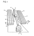
- Fig. 1 illustrates a concentrator solar photovoltaic power generating apparatus 10 according to one embodiment of the present invention which a sun tracking apparatus 12 is furnished with, in a perspective view.
- the sun tracking apparatus 12 is configured to move and constantly direct the apparatus 10 to the sun.
- the apparatus 12 includes a tracking motor 14, an inclined beam 16, an altitude correction motor 18 and a pair of backing plates 20.
- the inclined beam 16 is rotatably mounted around an inclined axis C which is inclined by a predetermined angle ⁇ , namely, an angle corresponding to the latitude, from the horizontal plane so that the beam 16 is placed and extends parallel to the earth's axis.
- the tracking motor 14 with a reduction gear changes the rotation angle of the inclined beam 16 around the inclined axis C.
- the backing plates 20 are rotatably mounted around the horizontal axis H at the intermediate portion of the inclined beam 16. And the altitude correction motor 18 changes the rotation angle of the backing plates 20 around the horizontal axis H.
- the apparatus 10 has a shape of a long box which has substantially greater dimensions in the longitudinal and lateral directions with respect to the height (or thickness). Each of the apparatus 10 is respectively placed upon and secured to the pair of the backing plates 20.
- the above-indicated sun tracking apparatus 12 is provided with a sunlight sensor and a control device (not shown).
- the control device calculates and determines the position of the sun on the basis of the signal from the sunlight sensor.
- the apparatus 12 drives the tracking motor 14 and the altitude correction motor 18 so that the apparatus 12 directs the concentrator solar photovoltaic power generating apparatus 10 to the sun, that is, a light receiving surface of the apparatus 10 faces toward the sun so that the axis of incidence of the sunlight is always substantially perpendicular to the light receiving surface of the apparatus 10.
- the tracking motor 14 is substantially employed for tracking control of the movement of the sun from the sunrise to the sunset, reflective of the rotation of the earth.
- the altitude correction motor 18 is substantially employed for control of the movement of the sun in the altitude direction, reflective of the revolution of the earth.
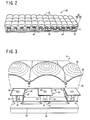
- Fig. 2 illustrates the above-indicated concentrator solar photovoltaic power generating apparatus 10 from the side direction in a perspective view.
- Fig. 3 illustrates a part of the apparatus 10 in an enlarged view.
- the apparatus 10 comprises a concentrator plate 30, a support plate 32 and a plurality of solar cell 34.
- the concentrator plate 30 is provided with a plurality of condenser lenses (or concentrator lenses) 28 functioning as a primary optical system or primary optics.
- the plate 30 in this embodiment has 36 condenser lenses.
- the support plate 32 is spaced backwards by a predetermined distance from the concentrator plate 30 and fixed parallel to the concentrator plate 30.
- Each of the respective solar cell 34 is disposed in the respective receiving position on which the cell 34 respectively receive the sunlight concentrated by each of a plurality of the above-indicated condenser lens 28 on the support plate 32.
- a reinforcing plate 38 is fixed on the periphery of the back of the support plate 32.
- each of a plurality of the above-indicated condenser lens 28 has a spherical surface on one side (or upper side), and a stepped surface that forms annularly, mutually convex and concave surface on the other side (or bottom side or back side).
- Such kind of the lens 28 is called a domelike Fresnel lens.
- the condenser lens 28 is mutually integrally constructed and formed of plastic material having superior optical characteristics such as PMMA, in a process of molding such as injection molding.
- the concentrator plate 30 is constructed of a plurality of the condenser lenses 28 which is thus integrally constructed, with a rectangular lens container frame 36 surrounding the lenses 28 on their peripheries.
- the support plate 32 is rectangular and has substantially equal dimensions in its longitudinal and lateral directions to the above-indicated lens container frame 36.
- the support plate 32 is constructed of a metal sheet of high thermal conductivity such as an aluminum alloy or a copper alloy.
- the support plate 32 is mutually connected with and parallel to the lens container frame 30 through connecting columns 37.
- a plurality of (power) generation modules 40 to generate electric power by the concentrated sunlight through the condenser lenses 28, and in the receiving position of the sunlight from each of the condenser lenses 28, that is, just below the lenses 28. As shown in Fig.
- the generation module 40 comprises a metallic base (seating plate) 42, a shielding plate 48 and a homogenizer 50 functioning as a secondary optical system or secondary optics.
- the base 42 is secured to the support plate 32 in abutting contact, and has the solar cell 34 disposed in the center.
- the shielding plate 48 is disposed and spaced by a predetermined distance above the base 42, which is supported by four columns 44 fixed on the base 42.
- the shielding plate 48 has a through-hole 46 formed substantially just above the solar cell 34.
- the homogenizer 50 is supported by the shielding plate 48, and guides the sunlight that has passed through the through-hole 46 on the shielding plate 48, to the receiving surface on the upper surface of the solar cell 34, in which the intensity of the sunlight is homogenized.
- the above-indicated shielding plate 48 is employed for transmitting only the sunlight which is concentrated through the condenser lens 28 toward the solar cell 34 for power generation, and for slowing down a rise in temperature around the solar cell 34 by shielding a light which is not available for power generation.
- the above-indicated homogenizer 50 has a form of a truncated pyramid in which its cross section becomes smaller as approaching the solar cell 34, that is, from a point around the through-hole 46 to the side of the solar cell 34.
- the homogenizer 50 homogenizes the intensity distribution of the optical energy within the cross section on the way that the sunlight travels toward the solar cell 34 with repeating internal total reflection (total reflection on the interface) on the internal surface.
- the homogenizer 50 has dimensions of 40 mm in height and of the same dimensions of the output surface (the surface on the side of the solar cell 34) as the surface of the solar cell 34, such as 7 mm in the longitudinal and lateral directions, to form a prism (or prismoidal) optical member.
- This homogenizer is made of such as borosilicate glass having the composition of, for instance, 69 wt% of SiO 2 , 9 wt% of Na 2 O, 8 wt% of K 2 O, 3 wt% of BaO, 10 wt% of B 2 O 3 and 1 wt% of As 2 O 3 , and approximately 1.516 of the refractive index.
- An anti-reflection layer 52 is laminated on the incident surface, the upper end surface, of the homogenizer 50 to restrain reflection of light by utilization of optical interference.
- the anti-reflection layer 52 is constructed of a layer having a bilayer of Al 2 O 3 and TiO 2 , or a multilayer of TiO 2 /Al 2 O 3 in this embodiment, and the thickness of it is, for instance, approximately 120 nm.
- the anti-reflection layer 52 is deposited in a vacuum evaporation method in this embodiment.
- the above-indicated solar cell 34 is constructed on a chip which has, for instance, well-known InGaP/InGaAs/Ge structure caused by crystal growth of the compound semiconductor of groups III-V on a single crystal substrate such as GaAs.
- the solar cell 34 has a multi-junction structure in which a plurality of kinds of p-n junctions respectively having a different absorption wavelength band.
- the multi-junction structure comprises a bottom junction layer, intermediate junction layer and upper junction layer which are successively laminated.
- the p-n junctions are respectively formed in the bottom, intermediate and upper junction layers, and are electrically connected in series and provided with absorption wavelength bands which have a different center wavelength.
- the above-indicated structure provides higher conversion efficiency due to wide absorption wavelength band in the wavelength band of the sunlight, for instance, due to absorption of the upper junction layer ranging from 300 to 630 nm, absorption of the intermediate junction layer ranging from 630 to 900 nm, and absorption of the upper junction layer ranging from 900 to 1700 nm.
- the solar cell 34 comprises a first lead electrode 56 and a second lead electrode 58.
- the first lead electrode is a tape- or ribbon-like a metal plate which is soldered at the whole bottom surface.
- the second lead electrode 58 is tape-like and soldered to the upper surface of the first lead electrode 56 at its end portion.
- the solar cell 34 is fixed on a bonding layer 60 at least at a portion, preferably, at the whole bottom surface as the whole portion is embedded, and consequently, the solar cell 34 is fixed on the base 42 in the center.
- the bonding layer 60 is formed of synthetic plastic sheet in which filler for increasing thermal conductivity including at least one of carbon, glass fiber, alumina (Al 2 O 3 ) powder, and metallic powder is dispersed.
- the solar cells 34 are each other connected in series through the first and second lead electrodes 56 and 58 so that high voltage can be output.
- a narrow space Between the bottom surface of the above-indicated homogenizer 50 and the solar cell 34 that is opposingly disposed to the homogenizer 50 there is a narrow space. And this intervening narrow space is filled with transparent resin to form a transparent resin member 62 in order to avoid entering of moisture.
- transparent resin member 62 material of high heat resistance and superior optical characteristics such as silicone gel is employed.
- a bottom portion of the homogenizer 50 and members placed below it including the solar cell 34 is coated with a non-transparent colored resin member such as white resin member 64, the white resin member 64 is bonded to and covers them with sufficient thickness of resin.
- the white resin member 64 functions as a shielding member, and includes filler within a self-adhesive RTV silicone resin to increase the effects of shielding from and reflection of sunlight.
- inorganic material such as calcium carbonate, titanium oxide, high purity alumina, high purity magnesium oxide, beryllium oxide, silica and/or aluminum nitride in a state of white and non-transparent powder.
- the above-indicated self-adhesive RTV silicone resin or rubber as a base resin includes an adhesive assistant such as silane coupling agent to increase adhesive properties, and, further, not less than 10 wt% of fluorosilicone resin having a low moisture permeation characteristic. This low moisture permeation characteristic of fluorosilicone resin restrains entering of moisture.
- the white resin member 64 functions as a sealing resin member for sealing to avoid entering of moisture.
- the low moisture permeation characteristic is indicated by a moisture permeability rate.
- the white resin member 64 has the moisture permeability rate of not more than 50 (g/m 2 ⁇ 24h) to rerstrain entering of moisture so that lowering of the generation efficiency of the power module 40 is restrained to obtain high durability.
- the above-identified moisture permeation rate is indicated by a value measured at the temperature of 40°C in the Moisture Permeation Test Method of Moisture Proof Packaging Material (Cup Method) in accordance with JIS Z0208 of the Japanese Industrial Standards in this embodiment.
- the base 42 having solar cell 34 in the center is coated with the white resin member 64 in a fluid state, for instance, in not more than 50 Pa ⁇ s of viscosity. Then a depressurized container contains the coated base 42 and a discharge of a solvent and deaeration is performed under the pressure of not more than 3 mmHg for not less than 60 seconds. And the coated members including the base 42 are processed in thermal hardening process at a predetermined temperature for hardening. Narrow spaces among the first lead electrode 56, the second lead electrode 58, the base 42 and the solar cell 34 is filled with the white resin member 64 to avoid entering of moisture by the negative pressure (or vacuum) deareration of the coated members.
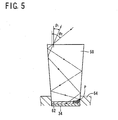
- the sun tracking apparatus 12 moves the thus-constructed concentrator solar photovoltaic power generating apparatus 10 to maintain the position so that the axis of incidence of the sunlight is always substantially perpendicular to the light receiving surface. Consequently, the concentrated sunlight by the condenser lens 28 travels through the through-hole 46 opened in the center of the shielding plate 48 and at the concentrated point of the concentrated sunlight. Then, the sunlight travels through the thin layer 54 and the anti-reflection layer 52 and enters the homogenizer 50 at the upper end portion at an incident angle ⁇ 1 . In the homogenizer 50 the light repeatedly travels and is reflected off side surfaces, that is, the light repeats total reflection on the side surface, as shown in Fig. 5 , to be mixed (homogenized), then enters the solar cell 34. Since the two-dimension distribution of the incident energy on the light receiving surface of the solar cell 34 is even, high conversion efficiency is achieved.
- the white resin member (shielding member) 64 to shield the transparent resin member 62 interposed between the bottom end surface of the homogenizer (columnar optical member) 50 and the solar cell 34 is provided, the bonded surface is not damaged due to deterioration of the transparent resin member 62 by light and, consequently, deterioration of the solar cell 34 due to entering moisture is restrained and high durability of the concentrator solar photovoltaic power generating apparatus 10 is achieved.
- the white resin member (shielding member) 64 is non-transparent colored resin member covering the transparent resin member 62, the white resin member 64 prevents deterioration of the transparent resin member 62 by sunlight, for the sunlight is difficult to reach the transparent resin member 62.
- the white resin member (shielding member) 64 is a non-transparent white resin including inorganic filler made of white and non-transparent powder, and is placed to also cover the outer circumferential surface of the bottom end portion of the homogenizer (columnar optical member) 50, the sunlight directing outwards through the outer surface in the bottom end portion of the homogenizer 50 is reflected by a plurality of times and reaches the solar cell 34, consequently, further higher generation efficiency is achieved. As shown by a dashed and dotted line in Fig.
- the white resin member 64 causes inwardly diffuse reflection of the light, and consequently, the above-indicated effect is remarkably achieved.
- the efficiency is 27% if the tracking error is 0°.
- the generation of the tracking error of 0.5° decreases the efficiency to 25.5%, and covering the bottom end portion of the homogenizer 50 with the white resin member 64 increases the efficiency to 26.2%.
- the concentrator solar photovoltaic power generating apparatus 10 since the light receiving surface of the solar cell 34 is provided with the anti-reflection layer 52 of a bilayer or multilayer of TiO 2 /Al 2 O 3 and the anti-reflection layer 52 is constituted of a material without deliquescence, further high durability of the concentrator solar photovoltaic power generating apparatus 10 is achieved.
- Fig. 6 , 7 and 8 illustrate results of durability tests by the inventors.
- Fig. 6 illustrates changes in relative amounts of power generation that were measured under concentrated ultraviolet radiation corresponding to the accumulated amount for exposure for the not less than 20-year equivalence in the positively or intentionally induced dew formation environment at the temperature of 20°C by water cooling, with respect to a generation module F provided with the same white resin member 64 and the anti-reflection layer (TiO 2 /Al 2 O 3 ) 52 as in the above-described embodiment, a generation module E with the anti-reflection layer 52 of which the material is replaced by ZnS/MgF 2 , the only difference between the module F and E, and generation modules A, B, C and D with transparent silicone resin member by which the white resin member 64 in the module F is replaced.
- a generation module F provided with the same white resin member 64 and the anti-reflection layer (TiO 2 /Al 2 O 3 ) 52 as in the above-described embodiment
- Fig. 7 illustrates characteristics of reduction in the relative generation amounts measured of the solar cells that were removed from a plurality of generation modules (equivalent to the above-indicated generation module A) in which the solar cell and the transparent resin member is sealed with a conventional silicone resin member, after exposed to the outdoor for four months. It was found the equivalent result to the test using the concentrated ultraviolet radiation in Fig. 6 in the deterioration speed.
- Fig. 8 illustrates the result of the field test in the outdoor using a plurality of the generation modules A in which the solar cell and the transparent resin member is sealed with a conventional silicone resin member, and the generation module C provided with the white resin member 64 and anti-reflection layer 52 equivalent to those in the above-described embodiment.
- the generation output of the generation module A decreased by 20% in a few months, however, that of the generation module C was maintained at a high level over a long period of time.
- Fig. 9 illustrates the results measured of an accelerating environment test by the inventors for durability.
- those generation module samples were placed in an accelerating environment test tank maintained at the temperature of 85°C and the relative humidity of 85%. Outputs from the generation module samples were measured at every predetermined time (or day).
- Fig. 9 the longitudinal axis shows the relative output value to the initial generation output value that was regarded as 1, and lateral axis shows the elapsed time.
- the effect for 2000 hours in the above accelerating environment test corresponds to that for six years in the outdoor. In general it is regarded as practically effective if the relative output of not less than 70% is maintained, that is, not more than 30% of deterioration is observed, after 2000 hours has elapsed. As apparent from Fig.
- the generation module samples of 10 wt%, 20 wt%, 30 wt% and 50 wt% of the rate of fluorosilicone resin according to the present embodiment were practically effective.
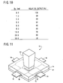
- Fig. 10 illustrates a table showing the result of measurement, the relationship between the surface roughness Ra and generation outputs of the generation module samples.
- the generation outputs shown in Fig. 10 are relative values to the generation module sample of surface roughness Ra of 0.3 nm that is regarded as 100.
- the generation output is reduced as the surface roughness Ra becomes larger.
- the generation output is not less than 81 % with the surface roughness Ra of not larger than 8 nm, the output is below 80% with the roughness Ra over 10 nm, and the output is approximately 50% with the roughness Ra of 30 nm. Less sufficiency in polishing the surface causes larger surface roughness Ra and leakage of light, and consequently, the decrease in generation efficiency.
- the white resin member 64 that covers the bottom portion of the homogenizer 50 and the solar cell 34 that is disposed as opposed to the bottom surface of the homogenizer 50 includes not less than 10 wt% of fluorosilicone resin, the low moisture permeation characteristic of fluorosilicone resin restrains entering of water vapor (or moisture), and consequently, it causes high durability and low deterioration in generation efficiency.
- the white resin member 64 has the permeability rate of not more than 50 g/m 2 ⁇ 24h, entering of water vapor (or moisture) is restrained, and consequently, it is provided with the generation module 40 of the concentrator solar photovoltaic power generating apparatus with high durability and low deterioration in its generation efficiency.
- the transparent resin member 62 is interposed between the bottom end surface of the homogenizer 50 and the solar cell 34, and the white resin member 64 is constituted of non-transparent and colored silicone resin including filler, the solar cell 34 is shielded and preferably protected from the external light.
- the homogenizer 50 is made of superior waterproof borosilicate glass, a little amount of sodium component in the homogenizer 50 is eluted upon reaching of water vapor on the surface of the homogenizer 50, and consequently, it causes high durability and low deterioration in generation efficiency.
- the glass of which the homogenizer 50 is constituted has the surface roughness Ra (arithmatic averaged roughness) of not larger than 10 nm, reflection factor of the internal side surface is high, and consequently, it causes high generation efficiency as the result of restraining leakage of light.
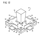
- Figs. 11 and 12 illustrate structures of generation modules of other embodiments according to the present invention.
- the same reference number as that in the embodiments described above are given for the equivalence and the description for it is omitted in the following descriptions.
- Figs. 11 and 12 illustrate other generation modules in which the bottom end portion of the homogenizer 50 is supported, and the modules is not provided with the shielding plate 48 to support the upper end portion of the homogenizer 50 and four columns to support the shielding plate 48.
- the generation module 70 is provided with the solar cell 34, the homogenizer 50, the first and second lead electrodes 56 and 58, the transparent resin member 62 and the white resin member 72 on the base 42, as well as the generation module 40.
- This module 70 is different from the module 40 in a few points as follows.
- the white resin member 72 is constituted of hard silicone resin including inorganic filler, as well as the white resin member 64 of the module 40 the white resin member 72 covers the transparent resin member 62 and is filled with narrow spaces among the first and second lead electrodes 56 and 58, the base 42 and the solar cell 34.
- the bottom end portion of the homogenizer 50 is covered with a building of the white resin member 72 constituted of the hard silicone resin and fixed. Then on the base 42 is comparatively thickly covered with the white resin member 74 constituted of soft silicone resin and including equivalent inorganic filler for waterproofing.
- the white resin members 72 and 74 function as the shielding members.
- the refractive index of the above white resin member 72 is approximately 1.42 and that of the homogenizer 50 is approximately 1.59, an incident ray at a shallow angle ( ⁇ 64°) is totally reflected off an interface, and an incident ray at a deep angle ( ⁇ 64 °) is diffused at an interface due to the white resin member 72 and a portion of the ray enters the solar cell 34, consequently, further high generation efficiency is provided.
- the white resin member 72 constituted of the hard silicone resin has no superior characteristic for waterproofing
- the white resin member 74 constituted of the soft silicone resin which has superior characteristic for waterproofing is employed for superior waterproofing.
- the generation module 76 is provided with the solar cell 34, the homogenizer 50, the first and second lead electrodes 56 and 58, the transparent resin member 62 and the white resin member 64 on the base 42, as well as the generation module 40.
- This module 76 is different from the module 40 in a point that the bottom end portion of the homogenizer 50 is fixed by a support plate 78.
- the support plate 78 is fixed by bolts 82 at the four corners of the base 42 with spacers 80 respectively interposed which are provided by a press-forming operation with a metal sheet such as a stainless steel sheet.
- a square-shaping through-hole 84 which is sufficiently larger than the cross section of the bottom end portion of the homogenizer 50 is opened, and projections 86 are inwardly protruded from an intermediate portion of the respective side of the through-hole 84.
- the projections 86 are formed in a U-shaping in the press-forming operation, and they receive and support the bottom end portion of the homogenizer 50 by a spring force.
- the white resin member 64 and the support plate 78 function as shielding members.
Landscapes
- Engineering & Computer Science (AREA)
- Life Sciences & Earth Sciences (AREA)
- Sustainable Development (AREA)
- Physics & Mathematics (AREA)
- Sustainable Energy (AREA)
- Thermal Sciences (AREA)
- Chemical & Material Sciences (AREA)
- Combustion & Propulsion (AREA)
- Mechanical Engineering (AREA)
- General Engineering & Computer Science (AREA)
- Photovoltaic Devices (AREA)
Applications Claiming Priority (1)
| Application Number | Priority Date | Filing Date | Title |
|---|---|---|---|
| PCT/JP2006/321106 WO2008050392A1 (fr) | 2006-10-24 | 2006-10-24 | Appareil photovoltaïque à concentration |
Publications (2)
| Publication Number | Publication Date |
|---|---|
| EP2077586A1 true EP2077586A1 (de) | 2009-07-08 |
| EP2077586A4 EP2077586A4 (de) | 2015-03-25 |
Family
ID=39324207
Family Applications (1)
| Application Number | Title | Priority Date | Filing Date |
|---|---|---|---|
| EP06822086.2A Withdrawn EP2077586A4 (de) | 2006-10-24 | 2006-10-24 | Konzentrierende photovolataic-vorrichtung |
Country Status (3)
| Country | Link |
|---|---|
| EP (1) | EP2077586A4 (de) |
| IL (1) | IL184507A (de) |
| WO (1) | WO2008050392A1 (de) |
Cited By (13)
| Publication number | Priority date | Publication date | Assignee | Title |
|---|---|---|---|---|
| US7873257B2 (en) | 2007-05-01 | 2011-01-18 | Morgan Solar Inc. | Light-guide solar panel and method of fabrication thereof |
| WO2011097704A1 (en) * | 2010-02-10 | 2011-08-18 | Quadra Solar Corporation | Concentrated photovoltaic and thermal system |
| ES2365959A1 (es) * | 2010-12-22 | 2011-10-14 | Abengoa Solar New Technologies S.A. | Módulo de concentración solar fotovoltaica y disposición modular que comprende dicho módulo. |
| WO2012014088A2 (en) | 2010-07-30 | 2012-02-02 | Morgan Solar Inc. | Light-guide solar module, method of fabrication thereof, and panel made therefrom |
| WO2012045895A3 (es) * | 2010-10-07 | 2012-08-09 | Renovalia Energy, S.A. | Receptor para sistemas de concentración solar con homogenización de la luz |
| US8328403B1 (en) | 2012-03-21 | 2012-12-11 | Morgan Solar Inc. | Light guide illumination devices |
| CN103532486A (zh) * | 2013-09-15 | 2014-01-22 | 北京凡元兴科技有限公司 | 一种可调节光量的太阳能聚焦系统 |
| US8816195B1 (en) * | 2009-06-05 | 2014-08-26 | The Boeing Company | Light shield for solar concentrators |
| ES2491017R1 (es) * | 2013-03-04 | 2014-11-06 | Daido Steel Co., Ltd. | Receptor para módulo de generación de energía fotovoltaica concentrador |
| US8885995B2 (en) | 2011-02-07 | 2014-11-11 | Morgan Solar Inc. | Light-guide solar energy concentrator |
| US9040808B2 (en) | 2007-05-01 | 2015-05-26 | Morgan Solar Inc. | Light-guide solar panel and method of fabrication thereof |
| US9337373B2 (en) | 2007-05-01 | 2016-05-10 | Morgan Solar Inc. | Light-guide solar module, method of fabrication thereof, and panel made therefrom |
| US9577131B2 (en) | 2013-03-26 | 2017-02-21 | Sumitomo Electric Industries, Ltd. | Concentrator photovoltaic module, concentrator photovoltaic panel, and flexible printed circuit for concentrator photovoltaic module |
Families Citing this family (5)
| Publication number | Priority date | Publication date | Assignee | Title |
|---|---|---|---|---|
| CN101521242A (zh) * | 2009-03-11 | 2009-09-02 | 杨振宇 | 高效太阳能电池及其制造方法 |
| WO2010137687A1 (ja) * | 2009-05-28 | 2010-12-02 | 京セラ株式会社 | 光電変換装置用部品、光電変換装置および光電変換モジュール |
| CN102447426A (zh) * | 2010-09-30 | 2012-05-09 | 谢显春 | 一种可加装聚光光导管的太阳能发电装置 |
| TWI484115B (zh) * | 2012-08-31 | 2015-05-11 | George Uh-Schu Liau | 光電盒 |
| JP6131667B2 (ja) * | 2013-03-26 | 2017-05-24 | 住友電気工業株式会社 | 太陽光発電モジュールおよび太陽光発電パネル |
Family Cites Families (8)
| Publication number | Priority date | Publication date | Assignee | Title |
|---|---|---|---|---|
| US4029519A (en) * | 1976-03-19 | 1977-06-14 | The United States Of America As Represented By The United States Energy Research And Development Administration | Solar collector having a solid transmission medium |
| JPH09176323A (ja) * | 1995-12-22 | 1997-07-08 | Pola Chem Ind Inc | フッ素化シリコーン樹脂及びその製造方法 |
| JP4270689B2 (ja) * | 1999-11-24 | 2009-06-03 | 本田技研工業株式会社 | 太陽光発電装置 |
| JP2002289897A (ja) * | 2001-03-23 | 2002-10-04 | Canon Inc | 集光型太陽電池モジュール及び集光型太陽光発電システム |
| JP2003174183A (ja) * | 2001-12-07 | 2003-06-20 | Daido Steel Co Ltd | 集光型太陽光発電装置 |
| JP4269651B2 (ja) * | 2002-11-19 | 2009-05-27 | 大同特殊鋼株式会社 | 集光型太陽光発電装置 |
| JP2005317756A (ja) * | 2004-04-28 | 2005-11-10 | Sharp Corp | 太陽電池パネル |
| JP2006278581A (ja) * | 2005-03-28 | 2006-10-12 | Daido Steel Co Ltd | 集光型太陽光発電装置、および、それに使用する光学部材 |
-
2006
- 2006-10-24 WO PCT/JP2006/321106 patent/WO2008050392A1/ja not_active Ceased
- 2006-10-24 EP EP06822086.2A patent/EP2077586A4/de not_active Withdrawn
-
2007
- 2007-07-09 IL IL184507A patent/IL184507A/en not_active IP Right Cessation
Cited By (18)
| Publication number | Priority date | Publication date | Assignee | Title |
|---|---|---|---|---|
| US7873257B2 (en) | 2007-05-01 | 2011-01-18 | Morgan Solar Inc. | Light-guide solar panel and method of fabrication thereof |
| US7991261B2 (en) | 2007-05-01 | 2011-08-02 | Morgan Solar Inc. | Light-guide solar panel and method of fabrication thereof |
| US8152339B2 (en) | 2007-05-01 | 2012-04-10 | Morgan Solar Inc. | Illumination device |
| US9335530B2 (en) | 2007-05-01 | 2016-05-10 | Morgan Solar Inc. | Planar solar energy concentrator |
| US9337373B2 (en) | 2007-05-01 | 2016-05-10 | Morgan Solar Inc. | Light-guide solar module, method of fabrication thereof, and panel made therefrom |
| US9040808B2 (en) | 2007-05-01 | 2015-05-26 | Morgan Solar Inc. | Light-guide solar panel and method of fabrication thereof |
| US8816195B1 (en) * | 2009-06-05 | 2014-08-26 | The Boeing Company | Light shield for solar concentrators |
| WO2011097704A1 (en) * | 2010-02-10 | 2011-08-18 | Quadra Solar Corporation | Concentrated photovoltaic and thermal system |
| WO2012014088A2 (en) | 2010-07-30 | 2012-02-02 | Morgan Solar Inc. | Light-guide solar module, method of fabrication thereof, and panel made therefrom |
| WO2012045895A3 (es) * | 2010-10-07 | 2012-08-09 | Renovalia Energy, S.A. | Receptor para sistemas de concentración solar con homogenización de la luz |
| ES2365959A1 (es) * | 2010-12-22 | 2011-10-14 | Abengoa Solar New Technologies S.A. | Módulo de concentración solar fotovoltaica y disposición modular que comprende dicho módulo. |
| US8885995B2 (en) | 2011-02-07 | 2014-11-11 | Morgan Solar Inc. | Light-guide solar energy concentrator |
| US8657479B2 (en) | 2012-03-21 | 2014-02-25 | Morgan Solar Inc. | Light guide illumination devices |
| US8328403B1 (en) | 2012-03-21 | 2012-12-11 | Morgan Solar Inc. | Light guide illumination devices |
| ES2491017R1 (es) * | 2013-03-04 | 2014-11-06 | Daido Steel Co., Ltd. | Receptor para módulo de generación de energía fotovoltaica concentrador |
| US9577131B2 (en) | 2013-03-26 | 2017-02-21 | Sumitomo Electric Industries, Ltd. | Concentrator photovoltaic module, concentrator photovoltaic panel, and flexible printed circuit for concentrator photovoltaic module |
| CN103532486A (zh) * | 2013-09-15 | 2014-01-22 | 北京凡元兴科技有限公司 | 一种可调节光量的太阳能聚焦系统 |
| CN103532486B (zh) * | 2013-09-15 | 2016-08-31 | 周庆芬 | 一种可调节光量的太阳能聚焦系统 |
Also Published As
| Publication number | Publication date |
|---|---|
| EP2077586A4 (de) | 2015-03-25 |
| IL184507A (en) | 2012-05-31 |
| WO2008050392A1 (fr) | 2008-05-02 |
| IL184507A0 (en) | 2009-02-11 |
Similar Documents
| Publication | Publication Date | Title |
|---|---|---|
| US20080087323A1 (en) | Concentrator Solar Photovoltaic Power Generating Apparatus | |
| EP2077586A1 (de) | Konzentrierende photovolataic-vorrichtung | |
| JP2006313810A (ja) | 集光型太陽光発電装置 | |
| US8039731B2 (en) | Photovoltaic concentrator for solar energy system | |
| US6365823B1 (en) | Solar cell module and manufacturing method thereof | |
| US20060283495A1 (en) | Method and system for integrated solar cell using a plurality of photovoltaic regions | |
| JP6416333B2 (ja) | 太陽電池モジュール | |
| US20160276514A1 (en) | Solar energy collection systems utilizing holographic optical elements useful for building integrated photovoltaics | |
| JP4747663B2 (ja) | 集光型太陽光発電装置 | |
| JP4821033B2 (ja) | 集光型太陽光発電ユニットおよびその柱状光学ガラス部材 | |
| AU2010201428A1 (en) | Asymmetric parabolic compound concentrator with photovoltaic cells | |
| US20180138346A1 (en) | Solar Energy Collection Systems Utilizing Holographic Optical Elements Useful for Building Integrated Photovoltaics | |
| WO2013047424A1 (ja) | 太陽光発電装置 | |
| JP5929578B2 (ja) | 太陽電池モジュール及び太陽電池モジュール集合体 | |
| WO2013002093A1 (ja) | 太陽光発電装置 | |
| KR101898593B1 (ko) | 태양전지 모듈 | |
| JP2003069070A (ja) | 太陽電池モジュール | |
| KR20080021652A (ko) | 복수의 광발전 영역을 사용하는 통합된 솔라 셀 시스템 및방법 | |
| CN224192362U (zh) | 光伏组件 | |
| CN121310720B (zh) | 间隙膜及光伏组件 | |
| JP5760788B2 (ja) | 集光型太陽光発電装置 | |
| KR20190096263A (ko) | 집광식 태양광 발전 모듈 | |
| CN120379397A (zh) | 光伏组件 | |
| JP2014175318A (ja) | 集光型太陽光発電モジュール用レシーバ | |
| GB2516011A (en) | Absorber device |
Legal Events
| Date | Code | Title | Description |
|---|---|---|---|
| PUAI | Public reference made under article 153(3) epc to a published international application that has entered the european phase |
Free format text: ORIGINAL CODE: 0009012 |
|
| 17P | Request for examination filed |
Effective date: 20090504 |
|
| AK | Designated contracting states |
Kind code of ref document: A1 Designated state(s): AT BE BG CH CY CZ DE DK EE ES FI FR GB GR HU IE IS IT LI LT LU LV MC NL PL PT RO SE SI SK TR |
|
| RBV | Designated contracting states (corrected) |
Designated state(s): AT BE BG CH CY CZ DE DK EE ES FI FR GB GR HU IE IS IT LI LT LU LV MC NL PL PT RO SE SI SK TR |
|
| DAX | Request for extension of the european patent (deleted) | ||
| A4 | Supplementary search report drawn up and despatched |
Effective date: 20150224 |
|
| RIC1 | Information provided on ipc code assigned before grant |
Ipc: H01L 31/054 20140101AFI20150218BHEP Ipc: H01L 31/048 20140101ALI20150218BHEP |
|
| STAA | Information on the status of an ep patent application or granted ep patent |
Free format text: STATUS: THE APPLICATION IS DEEMED TO BE WITHDRAWN |
|
| 18D | Application deemed to be withdrawn |
Effective date: 20150924 |