EP2077963B1 - Couche limite passive d'un système de purge pour commande de l'écoulement d'air d'entrée de nacelle - Google Patents
Couche limite passive d'un système de purge pour commande de l'écoulement d'air d'entrée de nacelle Download PDFInfo
- Publication number
- EP2077963B1 EP2077963B1 EP06825796A EP06825796A EP2077963B1 EP 2077963 B1 EP2077963 B1 EP 2077963B1 EP 06825796 A EP06825796 A EP 06825796A EP 06825796 A EP06825796 A EP 06825796A EP 2077963 B1 EP2077963 B1 EP 2077963B1
- Authority
- EP
- European Patent Office
- Prior art keywords
- section
- airflow
- passage
- nacelle
- inlet
- Prior art date
- Legal status (The legal status is an assumption and is not a legal conclusion. Google has not performed a legal analysis and makes no representation as to the accuracy of the status listed.)
- Not-in-force
Links
- 239000000446 fuel Substances 0.000 claims description 13
- 230000007704 transition Effects 0.000 claims description 4
- 230000008901 benefit Effects 0.000 description 8
- 238000000926 separation method Methods 0.000 description 3
- 230000008859 change Effects 0.000 description 2
- 238000002485 combustion reaction Methods 0.000 description 2
- 238000009792 diffusion process Methods 0.000 description 2
- 241000238631 Hexapoda Species 0.000 description 1
- 238000011109 contamination Methods 0.000 description 1
- 230000003247 decreasing effect Effects 0.000 description 1
- 238000007599 discharging Methods 0.000 description 1
- 230000002349 favourable effect Effects 0.000 description 1
- 238000004401 flow injection analysis Methods 0.000 description 1
- 238000000034 method Methods 0.000 description 1
- 239000000203 mixture Substances 0.000 description 1
- 238000012986 modification Methods 0.000 description 1
- 230000004048 modification Effects 0.000 description 1
- 238000010248 power generation Methods 0.000 description 1
- 238000011084 recovery Methods 0.000 description 1
- 230000004044 response Effects 0.000 description 1
Images

Classifications
-
- F—MECHANICAL ENGINEERING; LIGHTING; HEATING; WEAPONS; BLASTING
- F02—COMBUSTION ENGINES; HOT-GAS OR COMBUSTION-PRODUCT ENGINE PLANTS
- F02C—GAS-TURBINE PLANTS; AIR INTAKES FOR JET-PROPULSION PLANTS; CONTROLLING FUEL SUPPLY IN AIR-BREATHING JET-PROPULSION PLANTS
- F02C7/00—Features, components parts, details or accessories, not provided for in, or of interest apart form groups F02C1/00 - F02C6/00; Air intakes for jet-propulsion plants
- F02C7/04—Air intakes for gas-turbine plants or jet-propulsion plants
-
- B—PERFORMING OPERATIONS; TRANSPORTING
- B64—AIRCRAFT; AVIATION; COSMONAUTICS
- B64D—EQUIPMENT FOR FITTING IN OR TO AIRCRAFT; FLIGHT SUITS; PARACHUTES; ARRANGEMENT OR MOUNTING OF POWER PLANTS OR PROPULSION TRANSMISSIONS IN AIRCRAFT
- B64D33/00—Arrangement in aircraft of power plant parts or auxiliaries not otherwise provided for
- B64D33/02—Arrangement in aircraft of power plant parts or auxiliaries not otherwise provided for of combustion air intakes
-
- F—MECHANICAL ENGINEERING; LIGHTING; HEATING; WEAPONS; BLASTING
- F02—COMBUSTION ENGINES; HOT-GAS OR COMBUSTION-PRODUCT ENGINE PLANTS
- F02C—GAS-TURBINE PLANTS; AIR INTAKES FOR JET-PROPULSION PLANTS; CONTROLLING FUEL SUPPLY IN AIR-BREATHING JET-PROPULSION PLANTS
- F02C7/00—Features, components parts, details or accessories, not provided for in, or of interest apart form groups F02C1/00 - F02C6/00; Air intakes for jet-propulsion plants
- F02C7/04—Air intakes for gas-turbine plants or jet-propulsion plants
- F02C7/045—Air intakes for gas-turbine plants or jet-propulsion plants having provisions for noise suppression
-
- B—PERFORMING OPERATIONS; TRANSPORTING
- B64—AIRCRAFT; AVIATION; COSMONAUTICS
- B64D—EQUIPMENT FOR FITTING IN OR TO AIRCRAFT; FLIGHT SUITS; PARACHUTES; ARRANGEMENT OR MOUNTING OF POWER PLANTS OR PROPULSION TRANSMISSIONS IN AIRCRAFT
- B64D33/00—Arrangement in aircraft of power plant parts or auxiliaries not otherwise provided for
- B64D33/02—Arrangement in aircraft of power plant parts or auxiliaries not otherwise provided for of combustion air intakes
- B64D2033/0226—Arrangement in aircraft of power plant parts or auxiliaries not otherwise provided for of combustion air intakes comprising boundary layer control means
-
- F—MECHANICAL ENGINEERING; LIGHTING; HEATING; WEAPONS; BLASTING
- F05—INDEXING SCHEMES RELATING TO ENGINES OR PUMPS IN VARIOUS SUBCLASSES OF CLASSES F01-F04
- F05D—INDEXING SCHEME FOR ASPECTS RELATING TO NON-POSITIVE-DISPLACEMENT MACHINES OR ENGINES, GAS-TURBINES OR JET-PROPULSION PLANTS
- F05D2250/00—Geometry
- F05D2250/30—Arrangement of components
- F05D2250/32—Arrangement of components according to their shape
- F05D2250/324—Arrangement of components according to their shape divergent
-
- F—MECHANICAL ENGINEERING; LIGHTING; HEATING; WEAPONS; BLASTING
- F05—INDEXING SCHEMES RELATING TO ENGINES OR PUMPS IN VARIOUS SUBCLASSES OF CLASSES F01-F04
- F05D—INDEXING SCHEME FOR ASPECTS RELATING TO NON-POSITIVE-DISPLACEMENT MACHINES OR ENGINES, GAS-TURBINES OR JET-PROPULSION PLANTS
- F05D2250/00—Geometry
- F05D2250/70—Shape
- F05D2250/71—Shape curved
-
- F—MECHANICAL ENGINEERING; LIGHTING; HEATING; WEAPONS; BLASTING
- F05—INDEXING SCHEMES RELATING TO ENGINES OR PUMPS IN VARIOUS SUBCLASSES OF CLASSES F01-F04
- F05D—INDEXING SCHEME FOR ASPECTS RELATING TO NON-POSITIVE-DISPLACEMENT MACHINES OR ENGINES, GAS-TURBINES OR JET-PROPULSION PLANTS
- F05D2270/00—Control
- F05D2270/01—Purpose of the control system
- F05D2270/17—Purpose of the control system to control boundary layer
-
- Y—GENERAL TAGGING OF NEW TECHNOLOGICAL DEVELOPMENTS; GENERAL TAGGING OF CROSS-SECTIONAL TECHNOLOGIES SPANNING OVER SEVERAL SECTIONS OF THE IPC; TECHNICAL SUBJECTS COVERED BY FORMER USPC CROSS-REFERENCE ART COLLECTIONS [XRACs] AND DIGESTS
- Y10—TECHNICAL SUBJECTS COVERED BY FORMER USPC
- Y10T—TECHNICAL SUBJECTS COVERED BY FORMER US CLASSIFICATION
- Y10T137/00—Fluid handling
- Y10T137/0536—Highspeed fluid intake means [e.g., jet engine intake]
Definitions
- This invention relates to gas turbine engines and, more particularly, to a passive bleed system for reducing drag on a gas turbine propulsion system.
- Gas turbine engines are widely known and used for power generation and vehicle (e.g., aircraft) propulsion. There is a general trend to improve fuel efficiency of gas turbine engines.
- One technique for achieving better fuel efficiency is to reduce drag. For example, during flight, friction between airflow and the engine or other related components such as a nacelle produces drag that results in greater fuel consumption.
- the airflow can be laminar or turbulent. Laminar airflow generally produces less friction than turbulent airflow. Therefore, laminar airflow is desirable for reducing drag and improving fuel efficiency.
- a nacelle having the features of the preamble of claim 1 is disclosed in US-A 4132240 .
- Other nacelles having passages therethrough are disclosed in FR-A-779655 and DE-A-19720069 .
- the present invention provides a nacelle as recited in claim 1.
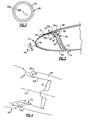
- Figure 1 illustrates a simplified view of selected portions of an example gas turbine engine 10, such as a gas turbine used for propulsion, circumferentially disposed about an engine centerline, or axial centerline axis 12.
- the gas turbine engine 10 includes a fan 14, a compressor 16, a combustion section 18, and a turbine section 20.
- air compressed in the compressor 16 is mixed with fuel that is burned in the combustion section 18 and expanded in turbine section 20.
- the air compressed in the compressor and the fuel mixture expanded in the turbine section 20 can both be referred to as a hot gas stream flow.
- the turbine section 20 includes rotors 22 and 24 that, in response to the expansion, rotate to drive the fan 14 and compressor 16.
- a nacelle 28 extends circumferentially about the gas turbine engine 10.
- the nacelle 28 includes an outside airflow surface 30a and an inside airflow surface 30b.
- a fan bypass passage 32 extends between the nacelle 28 and the gas turbine engine 10.
- the fan 14 draws air through an inlet lip 37 of the nacelle 28 into the bypass passage 32 and discharges the bypassed air out of a rear exhaust 34.
- the suction of the fan 14 in combination with the shape of the inlet lip 37 produces a suction side S at the inside airflow surface 30b relative to a pressure side P at the outside airflow surface 30a.
- a bleed passage 36 extends through the nacelle 28.
- the bleed passage 36 extends circumferentially entirely about the nacelle 28, as shown schematically in the axial view of Figure 2 .
- the bleed passage 36 extends only partially about the circumference.
- the bleed passage 36 may also include ribs or supports that extend through for structurally supporting the front portion of the nacelle relative to the aft portion.
- the bleed passage 36 provides the benefit of reducing drag on the nacelle 28 to thereby improve fuel efficiency.
- An additional benefit is reduced inlet distortion at low airspeed, high aircraft angle of attack.
- Figure 3 illustrates the portion of a nacelle 28 and bleed passage 36 according to the section shown in Figure 1 .
- the nacelle 28 includes a stagnation point 46 that intercepts an airflow 48 during, for example, high-speed cruise flight of the gas turbine engine 10. From the stagnation point 46, a portion of the airflow 48 flows over the outside airflow surface 30a and another portion of the airflow 48 flows over the inside airflow surface 30b.
- the airflow 48 over the outside airflow surface 30a is initially laminar. However, as the airflow continues to flow over the airflow surface 30a, it encounters a section 50 on the nacelle 28 beyond which the airflow is turbulent.
- laminar and turbulent as used in this description refer to a threshold of airflow vibration below which the airflow is laminar and above which the airflow is turbulent.
- the section 50 is where the airflow ceases to accelerate over the curved inlet lip, which is a condition that causes transition from laminar airflow to turbulent airflow 52.
- there are other causes of the turbulent airflow 52 such as roughness of the normally smooth outside airflow surface 30a caused by debris, or airflow distortion from a high angle of attack.
- the turbulent airflow 52 flows over the outside airflow surface 30a until it encounters an inlet 54 of the bleed passage 36.
- the inlet 54 includes a first section 56a forward of the inlet 54 and a second section 56b aft of the inlet 54.
- the first section 56a which is part of the outside airflow surface 30a, defines an imaginary tangential plane 58.
- the second section 56b is offset from the tangential plane 58 to provide a scoop that diverts at least a portion of the turbulent airflow 52 into the bleed passage 36. The offset of the scoop enables recovery of the ram pressure of the external air flow at the inlet of the bleed passage, increasing pressure differential that drives the flow through the passage.
- the second section 56b is offset a distance (as measured from a direction 90° relative to the tangential plane 58) of about 0.25 inches from the tangential plane 58. This provides the benefit of enough scoop height to divert a significant portion of, or in some examples all of, the turbulent boundary layer airflow 52 into the bleed passage 36. In other examples, the height of the offset may be greater than or less than in the disclosed example, depending upon the thickness of an expected turbulent boundary layer over the outside airflow surface 30a.
- a new boundary layer forms over the outside airflow surface 30a and is laminar.
- the shape of the nacelle 28 downstream of the inlet 54 is designed for a desired change in air pressure per unit distance from the outside airflow surface 30a (i.e., pressure profile) to maintain laminar airflow downstream of the inlet 54.
- the favorable pressure profile is achieved by designing the outside airflow surface 30a of the nacelle 28 with a desired curvature. Given this description, one of ordinary skill in the art will be able to recognize desirable nacelle 28 shapes to meet their particular needs. Downstream of the inlet 54, surface contamination is less likely to occur as this region does not project into the free stream.
- the bleed passage 36 includes a first curved section 68, a linear section 70, and a second curved section 72 having an outlet 74 for discharging the turbulent airflow 52 into the bypass passage 32.
- the outlet 74 is located forward of the fan 14 to exploit the pressure differential between the outside airflow surface 30a and an inside airflow surface 30b to draw the turbulent airflow 52 into the inlet 54.
- the pressure differential provides a passive system for drawing the turbulent airflow 52 into the bleed passage 36 without a need for a separate or additional component to draw in the turbulent airflow 52.
- the first curved section 68 extends between the inlet 54 and the beginning of the linear section 70 and includes a cross-sectional width W that progressively increases between the inlet 54 and the beginning of the linear section 70. This provides the benefit of diffusing the turbulent bleed airflow 52 as it flows through the bleed passage 36. That is, the first curved section 68 reduces the flow speed of the bleed airflow 52 such that the bleed airflow 52 can turn through the first curved section 68 and the second curved section 72 without significant pressure loss within the bleed passage 36. High pressure loss within the bleed passage is inefficient and would limit the bleed flow, effectively acting as a restriction in the passage.
- the cross-sectional area of the first curved section 68 at the inlet 54 is about 2.5 times smaller than the cross-sectional area at the beginning of the linear section 70.
- the ratio of about 2.5 provides a desirable diffusion of bleed airflow 52 to reduce pressure loss within the bleed passage 36. That is, if the ratio slows the bleed airflow 52 too much, a relatively greater pressure loss occurs because the increased diffusion will cause flow separation. Likewise, if the ratio slows the bleed airflow 52 too little, a relatively greater pressure loss occurs because the bleed airflow 52 will be traveling too fast which increases friction. At the bleed flow discharge 74 the passage area is decreased, thus forming a nozzle. Given this description, one of ordinary skill in the art will recognize other area ratios or other sections having area ratios that are suited to meet their particular needs.
- the bleed passage 36 gradually curves through the first curved section 68 and the second curved section 72. Such gradual curves, rather than relatively sharp curves (e.g., corners or 90° curves), provide the benefit of efficient airflow 52 through the bleed passage 36 without significant pressure loss.
- the disclosed examples provide the benefit of changing turbulent airflow 52 over the nacelle 28 to laminar airflow to reduce drag on the gas turbine nacelle 28 and thereby increase fuel efficiency.
- drag on the nacelle 28 is expected to be reduced by about 1/3 through use of the bleed passage 36.
- the discharge of the turbulent airflow 52 into the bypass passage 32 results in a nominally lower airflow pressure into the gas fan 14, which generally penalizes fuel efficiency.
- the net gain in fuel efficiency from reduced drag on the nacelle 28 is expected to be more significant than the net loss of fuel efficiency from lower airflow inlet pressure into the gas turbine engine 10.
- an overall fuel efficiency gain is expected.
- the example above refers to the operation of the bleed passage 36 at a cruise condition for which the external streamline direction and stagnation point 46 are generally as illustrated on Figure 3 , and the flow through the bleed passage 36 is fairly uniform around the circumference.
- the gas turbine engine 10 is shown in a low flight velocity, high angle of attack, and high engine power condition.
- the stagnation point 46' on the lower part of the inlet lip 37 is located aft on the outside airflow 30a surface, and there is a threat of flow separation at the lower part of the inside airflow surface 30b due to the extreme incidence and turning at the lower part of the inlet lip 37 of.
- the stagnation point 46' at the lower part of the inlet lip 37 is now approximately aligned with the inlet 54 of the bleed passage 36, creating a strong flow through the bleed passage 36 at the inlet lip 37.
- the bleed flow injection at the inside airflow surface 30b provides the benefit of energizing the internal flow into the fan 14, thus avoiding internal flow separation at the inlet lip 37.
Landscapes
- Engineering & Computer Science (AREA)
- Chemical & Material Sciences (AREA)
- Combustion & Propulsion (AREA)
- Mechanical Engineering (AREA)
- General Engineering & Computer Science (AREA)
- Aviation & Aerospace Engineering (AREA)
- Structures Of Non-Positive Displacement Pumps (AREA)
- Wind Motors (AREA)
- Physics & Mathematics (AREA)
- Fluid Mechanics (AREA)
- Control Of Turbines (AREA)
Claims (11)
- Nacelle (28) pour un système de moteur à turbine à gaz (10), comprenant :un carter ayant un côté de pression (P) et un côté d'aspiration (S) ; etun passage (36) s'étendant entre le côté de pression et le côté d'aspiration pour permettre un écoulement d'air à partir du côté de pression jusqu'au côté d'aspiration ; le passage (36) comportant une section (68) ayant un diamètre en section transversale augmentant de manière progressive ; caractérisée en ce quela section (68) s'étend entre une entrée de passage (54) au niveau du côté de pression et une section linéaire (70) du passage (36).
- Nacelle selon la revendication 1, dans laquelle la section (68) comporte une première aire en section transversale au niveau de l'entrée de passage (54) et une deuxième aire en section transversale au niveau de la section linéaire (70) qui est environ 2,5 fois supérieure à la première aire en section transversale.
- Nacelle selon la revendication 1 ou 2, dans laquelle la section (68) est une première section incurvée, le passage (36) comprenant en outre une deuxième section incurvée (72) reliée à la section linéaire (70) et ayant une sortie (74) au niveau du côté d'aspiration.
- Nacelle selon la revendication 1, dans laquelle le carter comporte une surface d'écoulement d'air (30a) et l'entrée de passage (54) s'étend à travers la surface d'écoulement d'air (30a), la surface d'écoulement d'air (30a) ayant une première section (50) en avant de l'entrée (54) par rapport à une direction de l'écoulement d'air et une deuxième section en arrière de l'entrée (54), la section avant (50) définissant un plan tangent (58), et dans laquelle la section arrière est espacée du plan tangent (58).
- Nacelle selon la revendication 4, dans laquelle la section arrière est espacée à une distance de décalage d'environ 0,25 pouces (6,34 mm) du plan tangent (58).
- Nacelle selon la revendication 1, dans laquelle le carter comporte une surface d'écoulement d'air (30a) ayant une section (50) où l'écoulement d'air effectue une transition d'un premier écoulement d'air qui est généralement laminaire à un deuxième écoulement d'air ayant une composante d'écoulement d'air turbulent, le passage (36) s'étendant à partir de la surface d'écoulement d'air (30a) en arrière de la section (50).
- Système de moteur à turbine à gaz (10) comprenant :une soufflante (14) pour l'admission d'air ;un compresseur (16) pour comprimer l'air ;une chambre de combustion (18) pour brûler du carburant en présence de l'air afin de produire un flux de gaz en expansion ;une turbine (20) entraînée par le flux de gaz en expansion pour entraîner la soufflante (14) et le compresseur (16) ;une nacelle selon la revendication 1, qui s'étend autour de la soufflante (14), du compresseur (16), de la chambre de combustion (18) et de la turbine (20), la nacelle (28) ayant une section avant qui comporte une surface extérieure d'écoulement d'air (30a) et une surface intérieure d'écoulement d'air (30b) par rapport à la soufflante (14) ; etledit passage (36) s'étendant entre la surface extérieure d'écoulement d'air (30a) et la surface intérieure d'écoulement d'air (30b) afin de permettre l'écoulement d'air entre la surface extérieure d'écoulement d'air (30a) et la surface intérieure d'écoulement d'air (30b).
- Système selon la revendication 7, dans lequel l'entrée de passage (36) est au niveau de la surface extérieure d'écoulement d'air (30a) en avant de la soufflante (14).
- Système selon la revendication 8, dans lequel le passage (36) comporte une sortie (74) au niveau de la surface intérieure d'écoulement d'air (30b), la sortie (74) étant en avant de la soufflante (14).
- Système selon la revendication 7, 8 ou 9, dans lequel la section (68) comporte une première aire en section transversale au niveau de l'entrée de passage (54) et une deuxième aire en section transversale au niveau de la section linéaire (70) qui est environ 2,5 fois supérieure à la première aire en section transversale.
- Système selon la revendication 7, dans lequel l'entrée de passage (54) s'étend à travers la surface extérieure d'écoulement d'air (30a), la surface extérieure d'écoulement d'air (30a) comportant une première section (80) en avant de l'entrée (54) par rapport à une direction d'écoulement d'air sur la surface extérieure d'écoulement d'air (30a) et une deuxième section en arrière de l'entrée (54), la section avant définissant un plan tangent (58), et dans lequel la section arrière est espacée du plan tangent (58).
Applications Claiming Priority (1)
| Application Number | Priority Date | Filing Date | Title |
|---|---|---|---|
| PCT/US2006/039797 WO2008045051A2 (fr) | 2006-10-12 | 2006-10-12 | Couche barrière passive d'un système de purge pour commande de l'écoulement d'air d'entrée de nacelle |
Publications (2)
| Publication Number | Publication Date |
|---|---|
| EP2077963A2 EP2077963A2 (fr) | 2009-07-15 |
| EP2077963B1 true EP2077963B1 (fr) | 2013-02-27 |
Family
ID=39283308
Family Applications (1)
| Application Number | Title | Priority Date | Filing Date |
|---|---|---|---|
| EP06825796A Not-in-force EP2077963B1 (fr) | 2006-10-12 | 2006-10-12 | Couche limite passive d'un système de purge pour commande de l'écoulement d'air d'entrée de nacelle |
Country Status (3)
| Country | Link |
|---|---|
| US (2) | US8844553B2 (fr) |
| EP (1) | EP2077963B1 (fr) |
| WO (1) | WO2008045051A2 (fr) |
Families Citing this family (14)
| Publication number | Priority date | Publication date | Assignee | Title |
|---|---|---|---|---|
| US8480350B2 (en) | 2006-10-12 | 2013-07-09 | United Technologies Corporation | Turbofan engine with variable bypass nozzle exit area and method of operation |
| US9789954B2 (en) * | 2014-04-25 | 2017-10-17 | Rohr, Inc. | Method of controlling boundary layer flow |
| US10189558B2 (en) | 2015-04-21 | 2019-01-29 | Rohr, Inc. | Optimized nacelle profile and plenum shape for boundary layer ingestion active laminar flow control |
| US9874228B2 (en) | 2015-05-15 | 2018-01-23 | Rohr, Inc. | Nacelle inlet with extended outer barrel |
| US9908620B2 (en) | 2015-05-15 | 2018-03-06 | Rohr, Inc. | Multi-zone active laminar flow control system for an aircraft propulsion system |
| GB201511454D0 (en) | 2015-06-30 | 2015-08-12 | Rolls Royce Plc | Aircraft engine nacelle |
| US10308368B2 (en) * | 2015-10-30 | 2019-06-04 | General Electric Company | Turbofan engine and method of reducing air flow separation therein |
| US10794281B2 (en) * | 2016-02-02 | 2020-10-06 | General Electric Company | Gas turbine engine having instrumented airflow path components |
| US9777633B1 (en) | 2016-03-30 | 2017-10-03 | General Electric Company | Secondary airflow passage for adjusting airflow distortion in gas turbine engine |
| US11073090B2 (en) | 2016-03-30 | 2021-07-27 | General Electric Company | Valved airflow passage assembly for adjusting airflow distortion in gas turbine engine |
| US10753278B2 (en) | 2016-03-30 | 2020-08-25 | General Electric Company | Translating inlet for adjusting airflow distortion in gas turbine engine |
| US11433990B2 (en) | 2018-07-09 | 2022-09-06 | Rohr, Inc. | Active laminar flow control system with composite panel |
| WO2020113110A1 (fr) * | 2018-11-27 | 2020-06-04 | Georgia Tech Research Corporation | Systèmes et procédés de régulation découlement aérodynamique |
| US11629651B2 (en) * | 2020-11-17 | 2023-04-18 | General Electric Company | Gas turbine engine having a turbomachine and an electric motor coupled to a propeller |
Family Cites Families (27)
| Publication number | Priority date | Publication date | Assignee | Title |
|---|---|---|---|---|
| FR779655A (fr) | 1934-01-02 | 1935-04-10 | Procédé de transformation de l'énergie calorifique en énergie cinétique ou potentielle | |
| NL243195A (fr) | 1958-09-10 | 1900-01-01 | ||
| US3446223A (en) * | 1966-02-04 | 1969-05-27 | Lockheed Aircraft Corp | Air intake for gas turbine engines |
| GB1228806A (fr) * | 1968-07-04 | 1971-04-21 | ||
| US3664612A (en) | 1969-12-22 | 1972-05-23 | Boeing Co | Aircraft engine variable highlight inlet |
| US3618876A (en) * | 1969-12-22 | 1971-11-09 | Boeing Co | Aircraft engine leading edge auxiliary air inlet |
| US3915413A (en) * | 1974-03-25 | 1975-10-28 | Gen Electric | Variable air inlet system for a gas turbine engine |
| US4379191A (en) * | 1975-08-13 | 1983-04-05 | Rohr Industries, Inc. | Honeycomb noise attenuation structure |
| US4132240A (en) * | 1977-03-28 | 1979-01-02 | General Electric Company | Variable double lip quiet inlet |
| US4504030A (en) * | 1982-12-06 | 1985-03-12 | United Technologies Corporation | Cooling means |
| US4749150A (en) * | 1985-12-24 | 1988-06-07 | Rohr Industries, Inc. | Turbofan duct with noise suppression and boundary layer control |
| GB2194592B (en) * | 1986-08-27 | 1990-07-04 | Rolls Royce Plc | Fluid outlet duct |
| DE3720318A1 (de) | 1987-06-19 | 1989-01-05 | Mtu Muenchen Gmbh | Gondel fuer strahltriebwerke |
| US4993663A (en) * | 1989-06-01 | 1991-02-19 | General Electric Company | Hybrid laminar flow nacelle |
| DE4009223A1 (de) * | 1990-03-22 | 1991-09-26 | Mtu Muenchen Gmbh | Propfan-turbotriebwerk |
| GB9025023D0 (en) * | 1990-11-16 | 1991-01-02 | Rolls Royce Plc | Engine nacelle |
| US5137230A (en) * | 1991-06-04 | 1992-08-11 | General Electric Company | Aircraft gas turbine engine bleed air energy recovery apparatus |
| US5269135A (en) * | 1991-10-28 | 1993-12-14 | General Electric Company | Gas turbine engine fan cooled heat exchanger |
| GB9424495D0 (en) * | 1994-12-05 | 1995-01-25 | Short Brothers Plc | Aerodynamic low drag structure |
| DE19720069A1 (de) * | 1996-08-24 | 1997-10-02 | Erich Dipl Ing Ufer | Flugzeug-FAN-Propeller und FAN-Triebwerke mit Einrichtungen zur Kontrolle des Lufteinlaufes, der Grenzschicht und des Triebwerklärmes |
| US5934611A (en) * | 1997-10-20 | 1999-08-10 | Northrop Grumman Corporation | Low drag inlet design using injected duct flow |
| US6050527A (en) * | 1997-12-19 | 2000-04-18 | The Boeing Company | Flow control device to eliminate cavity resonance |
| US6058696A (en) | 1997-12-22 | 2000-05-09 | United Technologies Corporation | Inlet and outlet module for a heat exchanger for a flowpath for working medium gases |
| US6851255B2 (en) * | 2002-12-18 | 2005-02-08 | Pratt & Whitney Canada Corp. | Normally open reverse flow flapper valve |
| US7185495B2 (en) * | 2004-09-07 | 2007-03-06 | General Electric Company | System and method for improving thermal efficiency of dry low emissions combustor assemblies |
| US7454894B2 (en) * | 2004-12-07 | 2008-11-25 | United Technologies Corporation | Supplemental oil cooler airflow for gas turbine engine |
| US7383686B2 (en) * | 2004-12-13 | 2008-06-10 | Honeywell International Inc. | Secondary flow, high pressure turbine module cooling air system for recuperated gas turbine engines |
-
2006
- 2006-10-12 EP EP06825796A patent/EP2077963B1/fr not_active Not-in-force
- 2006-10-12 WO PCT/US2006/039797 patent/WO2008045051A2/fr not_active Ceased
- 2006-10-12 US US12/446,786 patent/US8844553B2/en active Active
-
2014
- 2014-07-08 US US14/325,583 patent/US9644535B2/en active Active
Also Published As
| Publication number | Publication date |
|---|---|
| US9644535B2 (en) | 2017-05-09 |
| WO2008045051A3 (fr) | 2009-06-18 |
| WO2008045051A2 (fr) | 2008-04-17 |
| US8844553B2 (en) | 2014-09-30 |
| US20140321970A1 (en) | 2014-10-30 |
| US20100074739A1 (en) | 2010-03-25 |
| EP2077963A2 (fr) | 2009-07-15 |
Similar Documents
| Publication | Publication Date | Title |
|---|---|---|
| US9644535B2 (en) | Passive boundary layer bleed system for nacelle inlet airflow control | |
| US8839805B2 (en) | Passive boundary layer bleed system for nacelle inlet airflow control | |
| EP2060489B1 (fr) | Ensemble de flux de nacelle | |
| EP2098714B1 (fr) | Turboréacteur à double flux à taux de dilution élevé | |
| US8186942B2 (en) | Nacelle assembly with turbulators | |
| US8192147B2 (en) | Nacelle assembly having inlet bleed | |
| EP2685065B1 (fr) | Turbopropulseur | |
| CN107013268B (zh) | 用于喷气发动机排气的压缩整流罩 | |
| CN112061404B (zh) | 减轻机舱入口中的不利流条件 | |
| RU2645180C2 (ru) | Лопасть винта для турбомашины | |
| US4696159A (en) | Gas turbine outlet arrangement | |
| EP3428436B1 (fr) | Aéronef intégrant un système de récupération de poussée à l'aide de l'air de la cabine | |
| EP3009639B1 (fr) | Nacelle de moteur à turbine à gaz | |
| US11920539B1 (en) | Gas turbine exhaust nozzle noise abatement |
Legal Events
| Date | Code | Title | Description |
|---|---|---|---|
| PUAI | Public reference made under article 153(3) epc to a published international application that has entered the european phase |
Free format text: ORIGINAL CODE: 0009012 |
|
| 17P | Request for examination filed |
Effective date: 20090330 |
|
| AK | Designated contracting states |
Kind code of ref document: A2 Designated state(s): DE GB |
|
| R17D | Deferred search report published (corrected) |
Effective date: 20090618 |
|
| DAX | Request for extension of the european patent (deleted) | ||
| 17Q | First examination report despatched |
Effective date: 20120201 |
|
| REG | Reference to a national code |
Ref country code: DE Ref legal event code: R079 Ref document number: 602006034829 Country of ref document: DE Free format text: PREVIOUS MAIN CLASS: B64D0033020000 Ipc: F02C0007040000 |
|
| RIC1 | Information provided on ipc code assigned before grant |
Ipc: B64D 33/02 20060101ALI20120629BHEP Ipc: F02C 7/04 20060101AFI20120629BHEP |
|
| GRAP | Despatch of communication of intention to grant a patent |
Free format text: ORIGINAL CODE: EPIDOSNIGR1 |
|
| GRAS | Grant fee paid |
Free format text: ORIGINAL CODE: EPIDOSNIGR3 |
|
| GRAA | (expected) grant |
Free format text: ORIGINAL CODE: 0009210 |
|
| AK | Designated contracting states |
Kind code of ref document: B1 Designated state(s): DE GB |
|
| REG | Reference to a national code |
Ref country code: GB Ref legal event code: FG4D |
|
| REG | Reference to a national code |
Ref country code: DE Ref legal event code: R096 Ref document number: 602006034829 Country of ref document: DE Effective date: 20130425 |
|
| PLBE | No opposition filed within time limit |
Free format text: ORIGINAL CODE: 0009261 |
|
| STAA | Information on the status of an ep patent application or granted ep patent |
Free format text: STATUS: NO OPPOSITION FILED WITHIN TIME LIMIT |
|
| 26N | No opposition filed |
Effective date: 20131128 |
|
| REG | Reference to a national code |
Ref country code: DE Ref legal event code: R097 Ref document number: 602006034829 Country of ref document: DE Effective date: 20131128 |
|
| GBPC | Gb: european patent ceased through non-payment of renewal fee |
Effective date: 20131012 |
|
| REG | Reference to a national code |
Ref country code: DE Ref legal event code: R119 Ref document number: 602006034829 Country of ref document: DE Effective date: 20140501 |
|
| PG25 | Lapsed in a contracting state [announced via postgrant information from national office to epo] |
Ref country code: GB Free format text: LAPSE BECAUSE OF NON-PAYMENT OF DUE FEES Effective date: 20131012 |
|
| PG25 | Lapsed in a contracting state [announced via postgrant information from national office to epo] |
Ref country code: DE Free format text: LAPSE BECAUSE OF NON-PAYMENT OF DUE FEES Effective date: 20140501 |