EP2078146B1 - System zur regelung eines verbrennungsprozesses für eine gasturbine - Google Patents
System zur regelung eines verbrennungsprozesses für eine gasturbine Download PDFInfo
- Publication number
- EP2078146B1 EP2078146B1 EP07821174.5A EP07821174A EP2078146B1 EP 2078146 B1 EP2078146 B1 EP 2078146B1 EP 07821174 A EP07821174 A EP 07821174A EP 2078146 B1 EP2078146 B1 EP 2078146B1
- Authority
- EP
- European Patent Office
- Prior art keywords
- nox
- pulsation
- levels
- target
- control
- Prior art date
- Legal status (The legal status is an assumption and is not a legal conclusion. Google has not performed a legal analysis and makes no representation as to the accuracy of the status listed.)
- Not-in-force
Links
Images



Classifications
-
- F—MECHANICAL ENGINEERING; LIGHTING; HEATING; WEAPONS; BLASTING
- F23—COMBUSTION APPARATUS; COMBUSTION PROCESSES
- F23N—REGULATING OR CONTROLLING COMBUSTION
- F23N5/00—Systems for controlling combustion
- F23N5/003—Systems for controlling combustion using detectors sensitive to combustion gas properties
-
- F—MECHANICAL ENGINEERING; LIGHTING; HEATING; WEAPONS; BLASTING
- F02—COMBUSTION ENGINES; HOT-GAS OR COMBUSTION-PRODUCT ENGINE PLANTS
- F02C—GAS-TURBINE PLANTS; AIR INTAKES FOR JET-PROPULSION PLANTS; CONTROLLING FUEL SUPPLY IN AIR-BREATHING JET-PROPULSION PLANTS
- F02C9/00—Controlling gas-turbine plants; Controlling fuel supply in air- breathing jet-propulsion plants
- F02C9/16—Control of working fluid flow
- F02C9/24—Control of the pressure level in closed cycles
-
- F—MECHANICAL ENGINEERING; LIGHTING; HEATING; WEAPONS; BLASTING
- F02—COMBUSTION ENGINES; HOT-GAS OR COMBUSTION-PRODUCT ENGINE PLANTS
- F02K—JET-PROPULSION PLANTS
- F02K7/00—Plants in which the working fluid is used in a jet only, i.e. the plants not having a turbine or other engine driving a compressor or a ducted fan; Control thereof
- F02K7/02—Plants in which the working fluid is used in a jet only, i.e. the plants not having a turbine or other engine driving a compressor or a ducted fan; Control thereof the jet being intermittent, i.e. pulse-jet
-
- F—MECHANICAL ENGINEERING; LIGHTING; HEATING; WEAPONS; BLASTING
- F23—COMBUSTION APPARATUS; COMBUSTION PROCESSES
- F23N—REGULATING OR CONTROLLING COMBUSTION
- F23N5/00—Systems for controlling combustion
- F23N5/16—Systems for controlling combustion using noise-sensitive detectors
-
- F—MECHANICAL ENGINEERING; LIGHTING; HEATING; WEAPONS; BLASTING
- F05—INDEXING SCHEMES RELATING TO ENGINES OR PUMPS IN VARIOUS SUBCLASSES OF CLASSES F01-F04
- F05D—INDEXING SCHEME FOR ASPECTS RELATING TO NON-POSITIVE-DISPLACEMENT MACHINES OR ENGINES, GAS-TURBINES OR JET-PROPULSION PLANTS
- F05D2270/00—Control
- F05D2270/01—Purpose of the control system
- F05D2270/08—Purpose of the control system to produce clean exhaust gases
- F05D2270/082—Purpose of the control system to produce clean exhaust gases with as little NOx as possible
-
- F—MECHANICAL ENGINEERING; LIGHTING; HEATING; WEAPONS; BLASTING
- F05—INDEXING SCHEMES RELATING TO ENGINES OR PUMPS IN VARIOUS SUBCLASSES OF CLASSES F01-F04
- F05D—INDEXING SCHEME FOR ASPECTS RELATING TO NON-POSITIVE-DISPLACEMENT MACHINES OR ENGINES, GAS-TURBINES OR JET-PROPULSION PLANTS
- F05D2270/00—Control
- F05D2270/01—Purpose of the control system
- F05D2270/08—Purpose of the control system to produce clean exhaust gases
- F05D2270/083—Purpose of the control system to produce clean exhaust gases by monitoring combustion conditions
-
- F—MECHANICAL ENGINEERING; LIGHTING; HEATING; WEAPONS; BLASTING
- F05—INDEXING SCHEMES RELATING TO ENGINES OR PUMPS IN VARIOUS SUBCLASSES OF CLASSES F01-F04
- F05D—INDEXING SCHEME FOR ASPECTS RELATING TO NON-POSITIVE-DISPLACEMENT MACHINES OR ENGINES, GAS-TURBINES OR JET-PROPULSION PLANTS
- F05D2270/00—Control
- F05D2270/30—Control parameters, e.g. input parameters
- F05D2270/301—Pressure
-
- F—MECHANICAL ENGINEERING; LIGHTING; HEATING; WEAPONS; BLASTING
- F23—COMBUSTION APPARATUS; COMBUSTION PROCESSES
- F23N—REGULATING OR CONTROLLING COMBUSTION
- F23N2241/00—Applications
- F23N2241/20—Gas turbines
-
- F—MECHANICAL ENGINEERING; LIGHTING; HEATING; WEAPONS; BLASTING
- F23—COMBUSTION APPARATUS; COMBUSTION PROCESSES
- F23R—GENERATING COMBUSTION PRODUCTS OF HIGH PRESSURE OR HIGH VELOCITY, e.g. GAS-TURBINE COMBUSTION CHAMBERS
- F23R2900/00—Special features of, or arrangements for continuous combustion chambers; Combustion processes therefor
- F23R2900/00013—Reducing thermo-acoustic vibrations by active means
Definitions
- the invention pertains to a system for controlling the combustion process for a gas turbine and in particular a system for the active control of nitrogen oxide (NOx) emissions of the gas turbine and combustion pulsations.
- the system is particularly intended for gas turbine combustion systems comprising a plurality of pre-mix burners that lead to one single combustion chamber.
- Gas turbines are required to operate at ever increasing efficiencies while producing lower levels of pollutants in their exhaust gases. Their efficiency can be increased, for example, by increasing the flame temperatures, however this also increases the levels of pollutants, in particular NOx, which is an exponential function of the flame temperature.
- One known method to control the NOx levels in a turbine's exhaust gas is to operate the burners with a maintained lean flame, i.e. at a lean fuel-to-air ratio, which lowers the flame temperature.
- a lean flame can lead to pulsations of the flame, or combustion pressure oscillations, which can reduce the lifetime of a burner.
- the formation of NOx and pulsations are influenced by several interconnected physical mechanisms such as the ambient atmospheric conditions, fuel composition, firing and flame temperature, combustion homogeneity, burner velocity, and others.
- WO 2005/093326 discloses a gas turbine operating method for annularly arranged burners and combustion chambers that controls and reduces pressure pulsations by means of a system that individually actuates each burner and additionally monitors each burner using a sensor system.
- US 5,321,947 discloses a combustion system for a gas turbine engine comprising multiple swirler vanes arranged about a fuel injection nozzle.
- the combustion system is operated with a lean premix of fuel and with a cooled fuel injector in order to achieve reduced pollution.
- a low NOx level is maintained by a supply of combustible fuel into spaces between the swirler vanes, and combustion pressure oscillation are reduced by a continual supply of pilot fuel to the combustor at all operating conditions.
- EP 1 621 811 discloses a method of operating a combustion system for a gas turbine engine having a plurality of burners.
- the fuel-to-air ratio for one or more burners is primarily controlled based on measured pressure oscillations or pulsations.
- the fuel-to-air ratio is increased or decreased when pressure oscillations exceed a given lower or upper limit, respectively.
- the fuel-to-air ratio is reduced when NOx levels are exceeded.
- the fuel-to-air ratio for primary burners is increased while it is decreased for secondary burners.
- EP 1 286 031 discloses a gas turbine control apparatus comprising a means for frequency analysis of pressure oscillations in the combustion system and a control unit that controls, based on the result of the frequency analysis, the ratio of fuel and air supplied to the combustion chamber.
- EP 1 331 448 discloses a fuel control system for a gas turbine engine having a plurality of burners and a plurality of combustion chambers, where each of the burners is associated with a separate, "can-type" combustion chamber.
- the system independently adjusts the fuel-to-air ratio of each individual combustion chamber to control the NOx level and dynamic pressure in each combustion chamber based on measurement of the NOx level in the exhaust, pressure oscillations in each combustion chamber and fuel-to-air ratio variation among the burners. The adjustment is repeated until said variables are maintained within given ranges.
- the system is specifically designed for a gas turbine with multiple combustion chambers.
- EP 1 283 339 discloses a method of remote monitoring of a gas turbine engine that operates at low NOX emissions.
- the method is intended to prevent damage due to resonances with turbine combustion oscillations and to provide low-cost communication of data to a remote monitoring center. It includes the measurement of oscillations data separated into frequency spectrum and peak value data. If abnormal peak values occur, then the frequency spectrum is observed. Before combustion oscillations develop to a critical level, where damage may occur, instructions are sent to operate the engine in a low-load operation mode.
- the monitoring is communicated by low-cost means such as an ISDN-based line switching method.
- EP 0 529 900 discloses a gas turbine apparatus having multiple burners and an annular combustion chamber and control means to adjust the flow of fuel and/or air independently to each individual burner in view of controlling burner stability and NOx emissions.
- the individual adjustment is performed according to one or two sensed quantities relating to a combustion characteristic or performance quantity of each burner. Each quantity is measured separately, whereupon separate correction signals are determined for each. These are in turn added in order to generate a final control signal to a fuel and/or air valve.
- US 2004/011051 discloses a system for controlling the combustion process for a gas turbine according to the preamble of claim 1.
- the system is to control the combustion process such that the NOx emissions of the gas turbine meet environmental requirements. Simultaneously, it is to control the combustion pulsations at a level as low as possible.
- the present invention is directed to an active system for controlling the combustion process for a gas turbine, in particular the emissions of nitrogen oxides (NOx) of the gas turbine and the combustion pulsation levels in the combustion chamber, as defined in claim 1.
- NOx nitrogen oxides
- the first control level receives NOx emissions measurement data and NOx target values, as given by the environmental requirements, and generates a combustion pulsation target value that is based on the difference between the target NOx emissions level and the measured NOx emissions level; the generated combustion pulsation target value is cascaded to the second control level of the control system.
- the second level is a combustion pulsation control level and adjusts a fuel flow distribution to the main and supplementary burner groups of the multiple burners or to the main and supplementary stages of each of the multiple burners in the gas turbine combustion system.
- the combustion system operated with said fuel flow distribution meets the combustion pulsation target as well as the NOx emission target given by the environmental requirements.
- a gas turbine combustion system to which the cascade control system is applicable, includes main and supplementary burners arranged at the inlet to a single combustion chamber.
- the main and supplementary burners may be arranged in various ways.
- the main and supplementary burners are arranged alternately along the circumferential of the chamber inlet, or there can be a greater number of main burners compared to supplementary burners.
- the main burners are, for example, operated with a richer fuel than the supplementary burners, which allows a more stable combustion process.
- the greater flame stability is however at the expense of increased NOx emissions due to burners operating with the greater fuel-to-air ratio.
- a further gas turbine combustion system to which the cascade control system is applicable, includes multiple burners leading into one single combustion chamber, where each burner is associated with different burner stages, for example, a premixing stage, and a pilot stage configured in the form of a lance.
- the two stages can also be any two different pre-mixing stages.
- control system is applicable to a combustion system with multiple burners leading into one combustion chamber.
- the combustion system may include multiple burners and one combustion chamber, where all burners lead into that one combustion chamber.
- the combustion system may also include multiple burners and two combustion chambers arranged in sequence downstream from one another. Again, all burners lead into the one single, first combustion chamber.
- the NOx control level includes means to receive two sets of input values, the target NOx emissions levels as determined by environmental or government requirements and the NOx emissions levels as measured in the exhaust of the gas turbine.
- the NOx control level further includes means to calculate a pulsation target based on the difference between the measured and target NOx emissions levels.
- the pulsation target comprises one or more values of pulsation targets, where each of the one or more values is attributed to a predetermined pulsation frequency critical for the given gas turbine combustion system.
- the pulsation control level comprises means to receive pulsation measurement data, consisting of one or more pulsation levels measured in the gas turbine combustion system, a means to band-pass filter the pulsation measurement data, and means for measurement conditioning the band-pass filtered data.
- Measurement conditioning is a type of pre-processing the band-pass filtered data. It furthermore includes means for error processing, which determines the error between the measured pulsation levels and the calculated pulsation target values and further determines the error that is most relevant to the combustion system.
- the system includes means for calculating the supplementary fuel flow ratio ⁇ based on the error processing. The value of ⁇ is determined such that a NOx level target is fulfilled, while pulsations as low as possible are assured.
- the cascade control system according to the invention is a closed-loop system. As the combustion system is operated at a calculated fuel flow ratio y, the control system continuously receives measured pulsation and NOx levels and recalculates an optimum fuel flow ratio ⁇ .
- Pulsation levels in the combustion chamber can be measured more rapidly than NOx emissions in the exhaust of the turbine. For this reason, in an exemplary embodiment of the control system, the pulsation control level is adjusted to operate faster than the NOx emissions control level.
- the control system according to the invention is particularly applicable to a combustion system with multiple burners arranged circumferentially about the gas turbine rotor axis and leading into an annularly shaped combustion chamber. It is further applicable to a combustion system comprising multiple burners arranged in an array radially adjacent to the gas turbine rotor. This type of combustion system is also referred to as side-mounted.
- the cascade control system according to the invention achieves an improved and advantageous operation of a gas turbine combustion system in that it has a greater ability to meet the environmental requirements regarding NOx emissions. Additionally, as a result of the lowered pulsations levels of the combustion, the lifetime of the combustion system is increased.
- Figure 1 shows schematically the cascade control system S according to the invention, and in particular the cascade structure comprising the first or NOx control level 1 and the second or pulsation control level 2.
- the first control level 1 includes means 3 for continuously receiving measurement data NOx MEAS of NOx emissions from the exhaust of the gas turbine and for NOx target levels NOx TGT as given for example by government regulations.
- a NOx control means 4 calculates, based on the difference between NOx MEAS and NOx TGT , pulsation target values p TGT, FREQ-1 , P TGT, FREQ-2 , ... P TGT,FREQ-n , at selected frequencies FREQ_1, FREQ_2, ..., FREQ_n, which are critical for the given combustion system. These values are the lowest achievable pulsations levels corresponding to the NOx target level.
- the calculated target pulsations values are cascaded to the second control level 2 of the control system S. They are input to a receiving means 5 for the target pulsations levels p TGT, FREQ-1 , p TGT, FREQ-2 , ... p TGT, FREQ-n .
- the second control level 2 further includes means 6 for continuously receiving and band-pass filtering raw measured values p' of pulsations and means 7 for measurement conditioning the band-pass filtered measurement data.
- the measurement-conditioned data of pulsations p FREQ-1 , p FREQ-2 , ... p FREQ-n which is at the same critical frequencies as the target pulsation values, is also input to the receiving means 5.
- the receiving means 5 is connected to a means for error processing 8, which determines the error between measured and target pulsation level, which is most critical and relevant to the given combustion system. This critical error is at one of the critical frequencies.
- the pulsation control level 2 further includes a means for pulsation control 9, which calculates a fuel flow ratio ⁇ based on the selected critical error. The calculated fuel flow ratio ⁇ assures pulsations as close as possible to the target pulsation level.
- a control signal line 8' leads from the error processing means 8 to the NOx control means 4.
- the error processing means 8 sends information about a selected critical frequency to the NOx control means 4, at which the worst or the most relevant error between target and measured pulsation levels has been detected. It further instructs the NOx control means 4 to adjust the pulsation target level at that selected frequency and keep the target pulsation levels at the other critical frequencies unaltered.
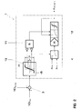
- Figure 2 shows in detail the elements of the first control level 1 of the cascade control system, in particular those of the means 4 for calculating the target pulsations. While the element 4, as shown in figure 1 , provides calculation of the target pulsations at several given critical frequencies, the figure 2 illustrates the calculation of the target pulsation level at one critical frequency FREQ.
- the control system S is applicable to combustion systems having one or several critical pulsation frequencies.
- the measured NOx level NOx MEAS and the target NOx level NOx TGT according to regulations are input with opposite signs to means 3, which calculates the difference between the two values.
- the difference is compared to a predetermined NOx emissions range of insensitivity, or dead band A, by a limiter 10.
- the output from the limiter 10 is then input to a logical AND-gate 11.
- the predetermined NOx emissions dead band A is derived from the environmental regulations and/or the accuracy of the control that needs to be achieved.
- a target pulsation level p TGT may remain the same. If however, the measured NOx level NOx MEAS is higher than the target NOx level NOx TGT and the difference is outside the predetermined dead band A, then the pulsation target p TGT is increased. At this point the dead band is reduced to a smaller range of insensitivity of size a until the difference between measured and target NOx levels are within this small dead band a. Once the difference is within the small dead band a, the dead band is again increased back to the original dead band A.
- the pulsation target p TGT is decreased.
- the dead band is reduced to a smaller range a until the difference between measured and target NOx levels are within this small dead band a. Once the difference is again within the small dead band a, the dead band is increased back to the original size A.
- p max and p min are maximum and minimum target pulsation levels considered acceptable for the given gas turbine combustion system. Such maximum and minimum pulsation levels are predetermined for each critical frequency for a given gas turbine combustion system.
- the FI-block 12 is a follow-up integrator for the calculation of a new target pulsation level, either increased or decreased, where the new target pulsation level will be between the limits of p max and p min .
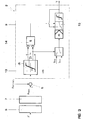
- Figure 3 shows an exemplary embodiment of the second control level 2, the pulsation control level.
- This level includes a band-pass filter 6, to which the measured pulsation levels p' are input in order to select pulsation data within a predetermined frequency band that is significant for a given gas turbine combustion system.
- the filtered data is then pre-processed, also called measurement conditioned, by the means 7.
- the filtered and measurement conditioned data is then input with a negative sign to means 5 together with the target pulsation values calculated by control level 1 and having a positive sign.
- Means 5 calculates the difference between the target pulsation levels and the measured and conditioned pulsation levels. The difference is compared to a predetermined pulsation levels dead band B by limiter 13.
- the output of limiter 13 is then input to a logical AND-gate 14.
- the fuel flow ratio ⁇ is held constant. If the measured pulsation level is higher than the target pulsation level and the difference is outside the dead band B, then the fuel flow ratio ⁇ is increased. At this point, the dead band is reduced to a small band b until the error is within this reduced dead band b. Once the error falls within this dead band b, the dead band is again increased to B.
- the fuel flow ratio ⁇ is decreased.
- the dead band is decreased to b until the error is within the reduced dead band b. Once the error falls within the dead band b, the dead band is again increased to B.
- the FI-block 15 calculates a fuel flow ratio that is within limits of maximum and minimum fuel flow ratio values ⁇ MAX and ⁇ MIN as predetermined for the given gas turbine combustion system.
- error processing means (such as indicated by element 8 in figure 1 ) is included following the means 5.
- the error processing means performs a weighted error selection and determines the error between measured and target pulsation levels that is most relevant. This frequency, at which this error occurs is then passed to the NOx control means 4 via control signal line 8'.
- the error selected by the error processing means 8 is input to the limiter 13 of the pulsation control means 9.
- Element 7 as shown in figure 3 is a device for pre-processing (measurement conditioning) the raw, band-pass filtered combustion pulsation data.
- the raw data p' cannot be used effectively as a feedback signal in a closed loop system such as the control system according to the invention because the raw data fluctuates too strongly. If unprocessed data were used, then fuel flow ratios would result that are based on extreme values that are not representative of the combustion process as a whole.
- the pre-processing conditioning provides a filtering of non-representative data fluctuations, where however the primary nature of the data is maintained.
- FIGS. 4a and b provide a further understanding of the control system according to the invention and in particular the trade-off between the NOx emissions and the combustion pulsation levels achievable by the cascade control system.
- Figure 4a shows the principle of operation for a given gas turbine, the curve showing NOx emissions and combustion pulsations for a pre-mixed flame as a function of the supplementary or fuel flow ratio ⁇ . With increasing ratio ⁇ , the NOx emissions gradually decrease, while the pulsation levels gradually increase. A lean pulsation limit p max is indicated for a given combustor.
- Figure 4b shows the same principle as in 4a, however with NOx levels and pulsation levels as controlled by the cascade control system.
- a gas turbine can initially be operated close to the lean pulsation limit p max in order to reduce NOx emissions to a minimum at NOx MIN . These minimum NOx emissions NOx MIN are however below the limit NOx TGT given by regulations and the pulsations levels are high at p MAX such that the gas turbine may suffer shortened lifetime due to the pulsations. If the gas turbine is now controlled by means of the cascade control system according to the invention, the gas turbine combustion system can be operated with reduced pulsation levels and NOx emission levels that still meet the NOx emissions requirements.
- a pulsation target p TGT is generated by the NOx control level or first level of the control system.
- the measured NOx emission is lower than the required NOx level NOx TGT , and the difference is outside a given dead band. Therefore the pulsation target is decreased from p max to p TGT .
- Each target pulsation level corresponds to the levels as adjusted by the NOx control level.
- the gas turbine combustion system will now, for example, be operated at the fuel flow ratio ⁇ NPCC as calculated by the NOx and pulsation cascade control system. While the combustion system is operated at this fuel flow ratio ⁇ NPCC , the control loop is closed by the input of new NOx emission and pulsation level measurement data to the control system, whereupon the fuel flow ratio is again adjusted.
- a NOx emission measurement can take, for example, about 20 seconds where the pulsation level measurement takes only approximately 1 second.
- the adjustment of the fuel flow ratio ⁇ is preferably adjusted within a time frame of a few seconds.
- Figure 5 shows a cross-section of gas turbine combustion system, to which the cascade control system is applicable.
- the cross-section is perpendicular to the turbine rotary axis 20 of a gas turbine and at the level of pre-mixing burners 21, 22.
- the pre-mixing burners include main burners 21 (darkened circles) and supplementary burners 22 (empty circles), which are arranged circumferentially about the turbine rotary axis 20.
- the burners extend into a ring-shaped combustion chamber that follows the burners in a direction out of the page.
- the main burners 21 and supplementary burners 22 are in this case arranged alternately about the circumference. They may be arranged also in any other way along the circumference.
- the main burners for example, operate with a richer fuel-to-air ratio and further away from the extinguishing limit than the supplementary burners.
- All burners are supplied with fuel by a fuel supply and distribution system 23 and via main fuel lines 24 (full lines) and supplementary fuel lines 25 (broken lines).
- main fuel lines 24 full lines
- supplementary fuel lines 25 broken lines.
- the figure is to be understood that fuel lines lead to all burners shown. However, for the sake of simplicity of the figure, only some of the fuel lines are illustrated completely, while the other fuel lines are partially indicated by either full lines or dotted lines extending radially away from the burners 21 and 22, respectively.
- the distribution of the fuel to the main and supplementary burners is controlled by the fuel distribution system 23.
- a control signal line 23' for the fuel flow ratio ⁇ leads from the cascade control system S to the fuel supply and distribution system 23.
- a pulsation level sensor 26 placed within the combustion chamber and a NOx emissions sensor 27 placed in the exhaust gas are each connected by means of a signal line 28 and 29, respectively, to the cascade control system S for inputting pulsation and emissions measurement data to the control system.
- Figure 6 shows a burner of a further gas turbine combustion system to which the cascade control system may be applied.
- the combustion system comprises, similar to that of figure 5 , multiple premixing burners arranged circumferentially about the rotary axis of a gas turbine, where each burner extends to the inlet of a ring-shaped combustion chamber C.
- each burner has a cone shape and comprises a main and supplementary stage.
- the cross-section along the longitudinal axis of the burner 30, as shown in figure 6 shows the two different stages, a main stage 31 arranged on the cone-shaped surface of the burner and a supplementary stage 32 arranged on a fuel lance and extending along the longitudinal axis of the cone-shaped burner.
- Fuel lines 33 and 34 lead from a fuel supply and distribution system 35 to the main and supplementary burners 31 and 32, respectively.
- the fuel from line 33 flows to openings arranged along the cone-shaped burner wall.
- the distribution of the fuel is controlled by the cascade control system S, which sends a control signal for the fuel flow ratio ⁇ to the supply system 35 via signal line 35'.
- a combustion pulsation level sensor 36 placed within the combustion chamber CC and NOx emissions sensor 37 placed in the exhaust of the gas turbine are connected to the cascade control system S by means of signal transmission lines 38 and 39, respectively, which send pulsation and emissions measurement data to the control system S.
- Figure 7 and 8 show a further exemplary combustion system for a gas turbine, to which the control system according to the invention may be applied.
- the figure shows a compressor C and a turbine T arranged on a rotor R with rotary axis 40.
- a combustion system comprises multiple burners 41 and 42, which lead into one single combustion chamber CC.
- the combustion chamber CC is approximately in the shape of a silo and arranged in side mounted manner, adjacent to the turbine. In the example shown, the longitudinal axis of the silo is along the radial with respect to the rotary axis 40 of the gas turbine.
- An annular inlet channel IL extends from the combustion chamber CC to the turbine T.
- All burners are supplied with fuel by a fuel supply and distribution system 43 and via main fuel lines 44 (full lines) and supplementary fuel lines 45 (broken lines).
- the distribution of the fuel to the main and supplementary burners is controlled by the cascade control system S, from which a control signal line 43' for the fuel flow ratio ⁇ leads to the fuel supply and distribution system 43.
- a pulsation level sensor 46 is placed within the combustion chamber CC, and a NOx emissions sensor 47 is positioned at a location in the exhaust gas suitable for reliable NOx measurements. Pulsation and emission measurement data are input to the cascade control system S by means of signal line 48 and 49, respectively.
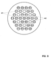
- Figure 8 shows in cross-section an exemplary arrangement of the main burners 41 and supplementary burners 42 in the combustion system of figure 7 . They are all arranged in a planar array.
- the main burners are supplied with a richer fuel-to-air ratio, while the supplementary burners are supplied with a leaner fuel.
Landscapes
- Engineering & Computer Science (AREA)
- Chemical & Material Sciences (AREA)
- Combustion & Propulsion (AREA)
- Mechanical Engineering (AREA)
- General Engineering & Computer Science (AREA)
- Physics & Mathematics (AREA)
- Fluid Mechanics (AREA)
- Regulation And Control Of Combustion (AREA)
Claims (11)
- System (S) zur Regelung des Verbrennungsprozesses für eine Gasturbine, das ein Gasturbinenverbrennungssystem mit Mehrfachbrennern umfasst, die sich hinein in eine einzelne Brennkammer (CC) erstrecken, wobei die Mehrfachbrenner Hauptbrenner (21, 41) und Zusatzbrenner (22, 42) umfassen oder jeder der Mehrfachbrenner (30) Hauptbrennerstufen (31) und Zusatzbrennerstufen (32) umfasst, dadurch gekennzeichnet, dass das Regelungssystem (S) ein geschlossenes Kaskadenregelungssystem ist, bei dem eine Kaskadenstruktur des Regelungssystems (S) zwei Regelungsstufen (1, 2) umfasst, wobei die erste Regelungsstufe (1) des Systems (S) Mittel (3), um gemessene Daten (NOxMEAS) für NOx-Werte kontinuierlich zu erfassen, sowie Mittel (4) umfasst, um Stickoxidemissionswerte im Abgas der Gasturbine zu regeln sowie Pulsationszielwerte (pTGT, FREQ-i) auf der Basis der Differenz zwischen den gemessenen NOx-Werten (NOxMEAS) und Ziel-NOx-Werten (NOxTGT) zu erzeugen und auf die zweite Regelungsstufe (2) anzuheben, und wobei die zweite Regelungsstufe (2) Mittel (6), um gemessene Pulsationswerte (p') kontinuierlich zu erfassen, sowie Mittel (9) umfasst, um den Verbrennungspulsationswert (p) zu regeln.
- System (S) nach Anspruch 1, dadurch gekennzeichnet, dass die erste Regelungsstufe (1) Mittel (3), um die Differenz zwischen gemessenen NOx-Emissionswerten (NOxMEAS) von der Gasturbine und Ziel-NOx-Emissionswerten (NOxTGT) zu bestimmen, sowie Mittel (12) umfasst, um Pulsationszielwerte bei einer oder mehreren vorbestimmten kritischen Frequenzen (pTGT, FREQ-i) auf der Basis der Differenz zwischen NOx-Emissionswerten (NOxMEAS, NOxTGT) zu erzeugen, und wobei die zweite Regelungsstufe (2) Mittel (13), um die Differenz zwischen gemessenen Pulsationsdaten (p') vom Gasturbinenverbrennungssystem und den durch die erste Regelungsstufe (1) erzeugten Zielpulsationswerten (pTGT,FREQ-i) zu bestimmen, sowie Mittel (9) umfasst, um ein Brennstoffströmungsverhältnis (γ) des Brennstoffstroms zu den Haupt- und Zusatzbrennern oder zu den Haupt- und Zusatzbrennerstufen zu erzeugen, definiert durch:

wobei:msupp der Massenstrom zu Zusatzbrennergruppen oder Zusatzbrennerstufen ist,mtotal der Gesamtbrennstoffmassenstrom ist,mmain der Massenstrom zu Hauptbrennergruppen oder Hauptbrennerstufen ist, und wobeider Wert des Brennstoffströmungsverhältnisses (γ) auf der Differenz zwischen gemessenen und Zielpulsationswerten (p', pTGT, FREQ-i) basiert. - System (S) nach Anspruch 2, dadurch gekennzeichnet, dass die erste Regelungsstufe (1) Mittel (3) beinhaltet, um gemessene NOx-Emissionswerte (NOxMEAS) und Ziel-NOx-Emissionswerte (NOxTGT) kontinuierlich zu erfassen und die Differenz zwischen den gemessenen und Ziel-NOx-Emissionswerten (NOxMEAS, NOxTGT) zu bestimmen, und wobei die zweite Regelungsstufe (2) Mittel (6) beinhaltet, um die gemessenen Pulsationswerte (p') kontinuierlich zu erfassen und durch einen Bandpassfilter zu leiten.
- System (S) nach Anspruch 3, dadurch gekennzeichnet, dass die zweite Regelungsstufe (2) Mittel (7) beinhaltet, um die im Bandpassfilter gefilterten Pulsationswerte vorzuverarbeiten.
- System (S) nach Anspruch 3, dadurch gekennzeichnet, dass die erste Regelungsstufe (1) einen Limiter (10), um die Differenz zwischen den gemessenen und Ziel-NOx-Emissionswerten (NOxMEAS, NOxTGT) mit einem vorbestimmten NOx-Emissions-Totband zu vergleichen, sowie weiterhin einen Folgeintegrator (12) beinhaltet, um die Zielpulsationswerte bei einer oder mehreren kritischen Frequenzen (pTGT, FREQ-i) auf der Basis des Vergleichs der Differenz der NOx-Emissionen mit dem vorbestimmten NOx-Emissions-Totband zu bestimmen.
- System (S) nach Anspruch 5, dadurch gekennzeichnet, dass der Folgeintegrator (12) so konfiguriert ist, dass er Zielpulsationswerte (pTGT, FREQ-i) erzeugt, die zwischen einem vorbestimmten maximalen und minimalen Zielpulsationswert (pmax, pmin) liegen.
- System (S) nach Anspruch 3 oder 4, dadurch gekennzeichnet, dass die zweite Regelungsstufe (2) Mittel (5), um die Mindestdifferenz zwischen einem vorverarbeiteten Pulsationswert (pFREQ) bei einer kritischen Frequenz und den Zielpulsationswerten (pTGT, FREQ-i) bei der Frequenz zu bestimmen, einen Limiter (13), um die Differenz mit einem vorbestimmten Pulsationswert-Totband zu vergleichen, sowie weiterhin einen Folgeintegrator (15) beinhaltet, um das Brennstoffströmungsverhältnis (γ) zu erzeugen.
- System (S) nach einem der Ansprüche 4 bis 6, dadurch gekennzeichnet, dass die zweite Regelungsstufe (2) Mittel (5), um die Differenz zwischen vorverarbeiteten Pulsationswerten (pFREQ-i) bei mehreren kritischen Frequenzen und den Zielpulsationswerten (pTGT, FREQ-i) bei den kritischen Frequenzen zu bestimmen, Fehlerverarbeitungsmittel (8), um aus den mehreren kritischen Frequenzen diejenige kritische Frequenz auszuwählen, bei der der relevanteste Fehler auftritt, einen Limiter (13), um die Differenz bei der ausgewählten Frequenz mit einem vorbestimmten Pulsationswert-Totband zu vergleichen, sowie einen Folgeintegrator (15) beinhaltet, um das Brennstoffströmungsverhältnis (γ) zu erzeugen.
- System (S) nach Anspruch 7 oder 8, dadurch gekennzeichnet, dass der Folgeintegrator (15) so konfiguriert ist, dass er ein Brennstoffströmungsverhältnis (γ) erzeugt, das zwischen einem vorbestimmten maximalen und minimalen Brennstoffströmungsverhältnis (γmax, γmin) liegt.
- System (S) nach einem der vorstehend aufgeführten Ansprüche, dadurch gekennzeichnet, dass die zweite Regelungsstufe (2) relativ zur ersten Regelungsstufe (1) mit einer höheren Geschwindigkeit arbeitet.
- System (S) nach Anspruch 7, dadurch gekennzeichnet, dass das System (S) eine Regelungssignalleitung (8') beinhaltet, die vom Fehlerverarbeitungsmittel (8) zum NOx-Regelungsmittel (4) führt, um Informationen über die ausgewählte kritische Frequenz, bei der der relevanteste Fehler auftritt, an das NOx-Regelungsmittel (4) weiterzuleiten und das NOx-Regelungsmittel (4) anzuweisen, den Zielpulsationswert bei der ausgewählten kritischen Frequenz einzustellen und die Pulsationswerte bei den anderen kritischen Frequenzen unverändert zu belassen.
Priority Applications (1)
| Application Number | Priority Date | Filing Date | Title |
|---|---|---|---|
| EP07821174.5A EP2078146B1 (de) | 2006-11-01 | 2007-10-11 | System zur regelung eines verbrennungsprozesses für eine gasturbine |
Applications Claiming Priority (3)
| Application Number | Priority Date | Filing Date | Title |
|---|---|---|---|
| EP06123306A EP1930569A1 (de) | 2006-11-01 | 2006-11-01 | System zur Regelung eines Verbrennungsprozesses für eine Gasturbine |
| PCT/EP2007/060807 WO2008052867A1 (en) | 2006-11-01 | 2007-10-11 | System for controlling a combustion process for a gas turbine |
| EP07821174.5A EP2078146B1 (de) | 2006-11-01 | 2007-10-11 | System zur regelung eines verbrennungsprozesses für eine gasturbine |
Publications (2)
| Publication Number | Publication Date |
|---|---|
| EP2078146A1 EP2078146A1 (de) | 2009-07-15 |
| EP2078146B1 true EP2078146B1 (de) | 2014-04-16 |
Family
ID=37891929
Family Applications (2)
| Application Number | Title | Priority Date | Filing Date |
|---|---|---|---|
| EP06123306A Withdrawn EP1930569A1 (de) | 2006-11-01 | 2006-11-01 | System zur Regelung eines Verbrennungsprozesses für eine Gasturbine |
| EP07821174.5A Not-in-force EP2078146B1 (de) | 2006-11-01 | 2007-10-11 | System zur regelung eines verbrennungsprozesses für eine gasturbine |
Family Applications Before (1)
| Application Number | Title | Priority Date | Filing Date |
|---|---|---|---|
| EP06123306A Withdrawn EP1930569A1 (de) | 2006-11-01 | 2006-11-01 | System zur Regelung eines Verbrennungsprozesses für eine Gasturbine |
Country Status (5)
| Country | Link |
|---|---|
| US (1) | US8434311B2 (de) |
| EP (2) | EP1930569A1 (de) |
| JP (1) | JP5014432B2 (de) |
| ES (1) | ES2471981T3 (de) |
| WO (1) | WO2008052867A1 (de) |
Families Citing this family (25)
| Publication number | Priority date | Publication date | Assignee | Title |
|---|---|---|---|---|
| EP1930569A1 (de) | 2006-11-01 | 2008-06-11 | ALSTOM Technology Ltd | System zur Regelung eines Verbrennungsprozesses für eine Gasturbine |
| US8408004B2 (en) * | 2009-06-16 | 2013-04-02 | General Electric Company | Resonator assembly for mitigating dynamics in gas turbines |
| US8370044B2 (en) * | 2009-06-26 | 2013-02-05 | General Electric Company | NOX compliant peak for gas turbine |
| DE102011117603A1 (de) | 2010-11-17 | 2012-05-24 | Alstom Technology Ltd. | Brennkammer und Verfahren zum Dämpfen von Pulsationen |
| JP5649949B2 (ja) * | 2010-12-28 | 2015-01-07 | 川崎重工業株式会社 | 燃焼装置 |
| US9074530B2 (en) * | 2011-01-13 | 2015-07-07 | General Electric Company | Stoichiometric exhaust gas recirculation and related combustion control |
| CH705179A1 (de) * | 2011-06-20 | 2012-12-31 | Alstom Technology Ltd | Verfahren zum Betrieb einer Verbrennungsvorrichtung sowie Verbrennungsvorrichtung zur Durchführung des Verfahrens. |
| US9631560B2 (en) | 2011-11-22 | 2017-04-25 | United Technologies Corporation | Fuel-air mixture distribution for gas turbine engine combustors |
| GB201317175D0 (en) | 2013-09-27 | 2013-11-06 | Rolls Royce Plc | An apparatus and a method of controlling the supply of fuel to a combustion chamber |
| JP5818945B2 (ja) * | 2014-05-20 | 2015-11-18 | 三菱日立パワーシステムズ株式会社 | ガスタービンの制御方法及びガスタービンの燃空比設定方法 |
| US9909508B2 (en) * | 2014-06-26 | 2018-03-06 | General Electric Company | Automatic combustion system characterization |
| US20160146462A1 (en) | 2014-11-21 | 2016-05-26 | Alstom Technology Ltd | PLANT, COMBUSTION APPARATUS, AND METHOD FOR REDUCTION OF NOx EMISSIONS |
| US9791351B2 (en) | 2015-02-06 | 2017-10-17 | General Electric Company | Gas turbine combustion profile monitoring |
| JP6508470B2 (ja) * | 2015-07-31 | 2019-05-08 | 三菱日立パワーシステムズ株式会社 | 燃料流量設定方法、この方法を実行する装置、この装置を備えるガスタービンプラント |
| US20170218851A1 (en) * | 2016-02-03 | 2017-08-03 | General Electric Company | Systems and Methods for NOx Measurement and Turbine Control |
| US10436123B2 (en) | 2017-03-08 | 2019-10-08 | General Electric Company | Methods and apparatus for closed-loop control of a gas turbine |
| US11092085B2 (en) * | 2017-03-14 | 2021-08-17 | General Electric Company | Method and system for controlling a sequential gas turbine engine |
| US11181274B2 (en) * | 2017-08-21 | 2021-11-23 | General Electric Company | Combustion system and method for attenuation of combustion dynamics in a gas turbine engine |
| US11156164B2 (en) | 2019-05-21 | 2021-10-26 | General Electric Company | System and method for high frequency accoustic dampers with caps |
| US11174792B2 (en) | 2019-05-21 | 2021-11-16 | General Electric Company | System and method for high frequency acoustic dampers with baffles |
| CN113239493B (zh) * | 2021-05-25 | 2023-12-26 | 王国峰 | 重型燃气轮机启机过程NOx排放性能建模和软件开发设计方法 |
| CN114811650B (zh) * | 2022-06-01 | 2023-02-07 | 清华大学 | 电加热稳燃装置、方法及存储介质 |
| DE102022211127A1 (de) | 2022-10-20 | 2024-04-25 | Robert Bosch Gesellschaft mit beschränkter Haftung | Verfahren, Recheneinheit und Computerprogramm zum Betreiben eines Bren-ners |
| GB202408240D0 (en) | 2024-06-10 | 2024-07-24 | Rolls Royce Plc | A gas turbine engine |
| GB202408238D0 (en) * | 2024-06-10 | 2024-07-24 | Rolls Royce Plc | Engine core size |
Family Cites Families (17)
| Publication number | Priority date | Publication date | Assignee | Title |
|---|---|---|---|---|
| JP2954401B2 (ja) | 1991-08-23 | 1999-09-27 | 株式会社日立製作所 | ガスタービン設備およびその運転方法 |
| US5321947A (en) | 1992-11-10 | 1994-06-21 | Solar Turbines Incorporated | Lean premix combustion system having reduced combustion pressure oscillation |
| US5544478A (en) * | 1994-11-15 | 1996-08-13 | General Electric Company | Optical sensing of combustion dynamics |
| JP2001082173A (ja) * | 1999-09-17 | 2001-03-27 | Hitachi Ltd | ガスタービン燃焼異常監視制御装置 |
| JP3810615B2 (ja) | 2000-05-18 | 2006-08-16 | 三菱重工業株式会社 | タービンの遠隔制御方法及びシステム |
| DE50108163D1 (de) * | 2001-05-01 | 2005-12-29 | Alstom Technology Ltd Baden | Schwingungsreduktion in einer Brennkammer |
| JP4056232B2 (ja) | 2001-08-23 | 2008-03-05 | 三菱重工業株式会社 | ガスタービン制御装置、ガスタービンシステム及びガスタービン遠隔監視システム |
| US6722135B2 (en) | 2002-01-29 | 2004-04-20 | General Electric Company | Performance enhanced control of DLN gas turbines |
| US6742341B2 (en) * | 2002-07-16 | 2004-06-01 | Siemens Westinghouse Power Corporation | Automatic combustion control for a gas turbine |
| JP3975232B2 (ja) * | 2002-10-22 | 2007-09-12 | 川崎重工業株式会社 | ガスタービンエンジンの制御方法および制御システム |
| US7563748B2 (en) | 2003-06-23 | 2009-07-21 | Cognis Ip Management Gmbh | Alcohol alkoxylate carriers for pesticide active ingredients |
| US7032388B2 (en) * | 2003-11-17 | 2006-04-25 | General Electric Company | Method and system for incorporating an emission sensor into a gas turbine controller |
| US6973791B2 (en) * | 2003-12-30 | 2005-12-13 | General Electric Company | Method and apparatus for reduction of combustor dynamic pressure during operation of gas turbine engines |
| DE102004036911A1 (de) | 2004-07-29 | 2006-03-23 | Alstom Technology Ltd | Betriebsverfahren für eine Feuerungsanlage |
| JP4119908B2 (ja) * | 2005-09-14 | 2008-07-16 | 三菱重工業株式会社 | ガスタービンの燃焼制御装置 |
| TW200801513A (en) | 2006-06-29 | 2008-01-01 | Fermiscan Australia Pty Ltd | Improved process |
| EP1930569A1 (de) | 2006-11-01 | 2008-06-11 | ALSTOM Technology Ltd | System zur Regelung eines Verbrennungsprozesses für eine Gasturbine |
-
2006
- 2006-11-01 EP EP06123306A patent/EP1930569A1/de not_active Withdrawn
-
2007
- 2007-10-11 EP EP07821174.5A patent/EP2078146B1/de not_active Not-in-force
- 2007-10-11 ES ES07821174.5T patent/ES2471981T3/es active Active
- 2007-10-11 WO PCT/EP2007/060807 patent/WO2008052867A1/en not_active Ceased
- 2007-10-11 JP JP2009535048A patent/JP5014432B2/ja not_active Expired - Fee Related
-
2009
- 2009-04-27 US US12/430,314 patent/US8434311B2/en not_active Expired - Fee Related
Also Published As
| Publication number | Publication date |
|---|---|
| US8434311B2 (en) | 2013-05-07 |
| EP2078146A1 (de) | 2009-07-15 |
| EP1930569A1 (de) | 2008-06-11 |
| ES2471981T3 (es) | 2014-06-27 |
| JP5014432B2 (ja) | 2012-08-29 |
| JP2010508469A (ja) | 2010-03-18 |
| WO2008052867A1 (en) | 2008-05-08 |
| US20090229238A1 (en) | 2009-09-17 |
Similar Documents
| Publication | Publication Date | Title |
|---|---|---|
| EP2078146B1 (de) | System zur regelung eines verbrennungsprozesses für eine gasturbine | |
| US6973791B2 (en) | Method and apparatus for reduction of combustor dynamic pressure during operation of gas turbine engines | |
| US10287993B2 (en) | Method and device for combustion with pulsed fuel split | |
| US8894408B2 (en) | Combustion apparatus | |
| EP1067338B1 (de) | Verfahren und Einrichtung zur Optimierung von NOx-Ausstoss in einer Gasturbine | |
| EP1974139B1 (de) | Kraftstoffmengenverhältnisregelung in einer verbrennungsvorrichtung mit mehreren kraftstoffzuleitungen | |
| US5303542A (en) | Fuel supply control method for a gas turbine engine | |
| US20070089425A1 (en) | Methods and systems for low emission gas turbine energy generation | |
| EP1808589A2 (de) | Zündbrennstoffflusseinstellung für Gasturbinenbrennkammern | |
| US7513117B2 (en) | Method for operating a furnace | |
| US20150113998A1 (en) | Gas Turbine Combustor and Gas Turbine Combustor Control Method | |
| US6679060B2 (en) | Method for operating a premix burner | |
| RU2719003C1 (ru) | Технология управления рабочим режимом системы сгорания путем использования пилотного воздуха | |
| US11274610B2 (en) | Combustion system control | |
| EP3222915B1 (de) | Gasturbinenanlage mit thermoakustischer instabilitätserkennung und verfahren zur steuerung einer gasturbinenanlage |
Legal Events
| Date | Code | Title | Description |
|---|---|---|---|
| PUAI | Public reference made under article 153(3) epc to a published international application that has entered the european phase |
Free format text: ORIGINAL CODE: 0009012 |
|
| 17P | Request for examination filed |
Effective date: 20090417 |
|
| AK | Designated contracting states |
Kind code of ref document: A1 Designated state(s): AT BE BG CH CY CZ DE DK EE ES FI FR GB GR HU IE IS IT LI LT LU LV MC MT NL PL PT RO SE SI SK TR |
|
| DAX | Request for extension of the european patent (deleted) | ||
| GRAP | Despatch of communication of intention to grant a patent |
Free format text: ORIGINAL CODE: EPIDOSNIGR1 |
|
| INTG | Intention to grant announced |
Effective date: 20131126 |
|
| GRAS | Grant fee paid |
Free format text: ORIGINAL CODE: EPIDOSNIGR3 |
|
| GRAA | (expected) grant |
Free format text: ORIGINAL CODE: 0009210 |
|
| AK | Designated contracting states |
Kind code of ref document: B1 Designated state(s): AT BE BG CH CY CZ DE DK EE ES FI FR GB GR HU IE IS IT LI LT LU LV MC MT NL PL PT RO SE SI SK TR |
|
| REG | Reference to a national code |
Ref country code: GB Ref legal event code: FG4D |
|
| REG | Reference to a national code |
Ref country code: CH Ref legal event code: EP |
|
| REG | Reference to a national code |
Ref country code: AT Ref legal event code: REF Ref document number: 662728 Country of ref document: AT Kind code of ref document: T Effective date: 20140515 |
|
| REG | Reference to a national code |
Ref country code: IE Ref legal event code: FG4D |
|
| REG | Reference to a national code |
Ref country code: DE Ref legal event code: R096 Ref document number: 602007036153 Country of ref document: DE Effective date: 20140522 |
|
| REG | Reference to a national code |
Ref country code: AT Ref legal event code: MK05 Ref document number: 662728 Country of ref document: AT Kind code of ref document: T Effective date: 20140416 |
|
| REG | Reference to a national code |
Ref country code: NL Ref legal event code: VDEP Effective date: 20140416 |
|
| REG | Reference to a national code |
Ref country code: LT Ref legal event code: MG4D |
|
| PG25 | Lapsed in a contracting state [announced via postgrant information from national office to epo] |
Ref country code: FI Free format text: LAPSE BECAUSE OF FAILURE TO SUBMIT A TRANSLATION OF THE DESCRIPTION OR TO PAY THE FEE WITHIN THE PRESCRIBED TIME-LIMIT Effective date: 20140416 Ref country code: LT Free format text: LAPSE BECAUSE OF FAILURE TO SUBMIT A TRANSLATION OF THE DESCRIPTION OR TO PAY THE FEE WITHIN THE PRESCRIBED TIME-LIMIT Effective date: 20140416 Ref country code: GR Free format text: LAPSE BECAUSE OF FAILURE TO SUBMIT A TRANSLATION OF THE DESCRIPTION OR TO PAY THE FEE WITHIN THE PRESCRIBED TIME-LIMIT Effective date: 20140717 Ref country code: BG Free format text: LAPSE BECAUSE OF FAILURE TO SUBMIT A TRANSLATION OF THE DESCRIPTION OR TO PAY THE FEE WITHIN THE PRESCRIBED TIME-LIMIT Effective date: 20140716 Ref country code: IS Free format text: LAPSE BECAUSE OF FAILURE TO SUBMIT A TRANSLATION OF THE DESCRIPTION OR TO PAY THE FEE WITHIN THE PRESCRIBED TIME-LIMIT Effective date: 20140816 Ref country code: NL Free format text: LAPSE BECAUSE OF FAILURE TO SUBMIT A TRANSLATION OF THE DESCRIPTION OR TO PAY THE FEE WITHIN THE PRESCRIBED TIME-LIMIT Effective date: 20140416 Ref country code: CY Free format text: LAPSE BECAUSE OF FAILURE TO SUBMIT A TRANSLATION OF THE DESCRIPTION OR TO PAY THE FEE WITHIN THE PRESCRIBED TIME-LIMIT Effective date: 20140416 |
|
| PG25 | Lapsed in a contracting state [announced via postgrant information from national office to epo] |
Ref country code: AT Free format text: LAPSE BECAUSE OF FAILURE TO SUBMIT A TRANSLATION OF THE DESCRIPTION OR TO PAY THE FEE WITHIN THE PRESCRIBED TIME-LIMIT Effective date: 20140416 Ref country code: LV Free format text: LAPSE BECAUSE OF FAILURE TO SUBMIT A TRANSLATION OF THE DESCRIPTION OR TO PAY THE FEE WITHIN THE PRESCRIBED TIME-LIMIT Effective date: 20140416 Ref country code: SE Free format text: LAPSE BECAUSE OF FAILURE TO SUBMIT A TRANSLATION OF THE DESCRIPTION OR TO PAY THE FEE WITHIN THE PRESCRIBED TIME-LIMIT Effective date: 20140416 Ref country code: PL Free format text: LAPSE BECAUSE OF FAILURE TO SUBMIT A TRANSLATION OF THE DESCRIPTION OR TO PAY THE FEE WITHIN THE PRESCRIBED TIME-LIMIT Effective date: 20140416 |
|
| PG25 | Lapsed in a contracting state [announced via postgrant information from national office to epo] |
Ref country code: PT Free format text: LAPSE BECAUSE OF FAILURE TO SUBMIT A TRANSLATION OF THE DESCRIPTION OR TO PAY THE FEE WITHIN THE PRESCRIBED TIME-LIMIT Effective date: 20140818 |
|
| REG | Reference to a national code |
Ref country code: DE Ref legal event code: R097 Ref document number: 602007036153 Country of ref document: DE |
|
| PG25 | Lapsed in a contracting state [announced via postgrant information from national office to epo] |
Ref country code: BE Free format text: LAPSE BECAUSE OF FAILURE TO SUBMIT A TRANSLATION OF THE DESCRIPTION OR TO PAY THE FEE WITHIN THE PRESCRIBED TIME-LIMIT Effective date: 20140416 Ref country code: DK Free format text: LAPSE BECAUSE OF FAILURE TO SUBMIT A TRANSLATION OF THE DESCRIPTION OR TO PAY THE FEE WITHIN THE PRESCRIBED TIME-LIMIT Effective date: 20140416 Ref country code: CZ Free format text: LAPSE BECAUSE OF FAILURE TO SUBMIT A TRANSLATION OF THE DESCRIPTION OR TO PAY THE FEE WITHIN THE PRESCRIBED TIME-LIMIT Effective date: 20140416 Ref country code: RO Free format text: LAPSE BECAUSE OF FAILURE TO SUBMIT A TRANSLATION OF THE DESCRIPTION OR TO PAY THE FEE WITHIN THE PRESCRIBED TIME-LIMIT Effective date: 20140416 Ref country code: EE Free format text: LAPSE BECAUSE OF FAILURE TO SUBMIT A TRANSLATION OF THE DESCRIPTION OR TO PAY THE FEE WITHIN THE PRESCRIBED TIME-LIMIT Effective date: 20140416 Ref country code: SK Free format text: LAPSE BECAUSE OF FAILURE TO SUBMIT A TRANSLATION OF THE DESCRIPTION OR TO PAY THE FEE WITHIN THE PRESCRIBED TIME-LIMIT Effective date: 20140416 |
|
| PLBE | No opposition filed within time limit |
Free format text: ORIGINAL CODE: 0009261 |
|
| STAA | Information on the status of an ep patent application or granted ep patent |
Free format text: STATUS: NO OPPOSITION FILED WITHIN TIME LIMIT |
|
| 26N | No opposition filed |
Effective date: 20150119 |
|
| REG | Reference to a national code |
Ref country code: DE Ref legal event code: R097 Ref document number: 602007036153 Country of ref document: DE Effective date: 20150119 |
|
| PG25 | Lapsed in a contracting state [announced via postgrant information from national office to epo] |
Ref country code: MC Free format text: LAPSE BECAUSE OF FAILURE TO SUBMIT A TRANSLATION OF THE DESCRIPTION OR TO PAY THE FEE WITHIN THE PRESCRIBED TIME-LIMIT Effective date: 20140416 Ref country code: LU Free format text: LAPSE BECAUSE OF FAILURE TO SUBMIT A TRANSLATION OF THE DESCRIPTION OR TO PAY THE FEE WITHIN THE PRESCRIBED TIME-LIMIT Effective date: 20141011 |
|
| REG | Reference to a national code |
Ref country code: CH Ref legal event code: PL |
|
| REG | Reference to a national code |
Ref country code: IE Ref legal event code: MM4A |
|
| PG25 | Lapsed in a contracting state [announced via postgrant information from national office to epo] |
Ref country code: SI Free format text: LAPSE BECAUSE OF FAILURE TO SUBMIT A TRANSLATION OF THE DESCRIPTION OR TO PAY THE FEE WITHIN THE PRESCRIBED TIME-LIMIT Effective date: 20140416 Ref country code: CH Free format text: LAPSE BECAUSE OF NON-PAYMENT OF DUE FEES Effective date: 20141031 Ref country code: LI Free format text: LAPSE BECAUSE OF NON-PAYMENT OF DUE FEES Effective date: 20141031 |
|
| REG | Reference to a national code |
Ref country code: FR Ref legal event code: ST Effective date: 20150630 |
|
| PG25 | Lapsed in a contracting state [announced via postgrant information from national office to epo] |
Ref country code: FR Free format text: LAPSE BECAUSE OF NON-PAYMENT OF DUE FEES Effective date: 20141031 |
|
| PG25 | Lapsed in a contracting state [announced via postgrant information from national office to epo] |
Ref country code: IE Free format text: LAPSE BECAUSE OF NON-PAYMENT OF DUE FEES Effective date: 20141011 |
|
| PG25 | Lapsed in a contracting state [announced via postgrant information from national office to epo] |
Ref country code: TR Free format text: LAPSE BECAUSE OF FAILURE TO SUBMIT A TRANSLATION OF THE DESCRIPTION OR TO PAY THE FEE WITHIN THE PRESCRIBED TIME-LIMIT Effective date: 20140416 Ref country code: MT Free format text: LAPSE BECAUSE OF FAILURE TO SUBMIT A TRANSLATION OF THE DESCRIPTION OR TO PAY THE FEE WITHIN THE PRESCRIBED TIME-LIMIT Effective date: 20140416 Ref country code: HU Free format text: LAPSE BECAUSE OF FAILURE TO SUBMIT A TRANSLATION OF THE DESCRIPTION OR TO PAY THE FEE WITHIN THE PRESCRIBED TIME-LIMIT; INVALID AB INITIO Effective date: 20071011 |
|
| REG | Reference to a national code |
Ref country code: DE Ref legal event code: R081 Ref document number: 602007036153 Country of ref document: DE Owner name: GENERAL ELECTRIC TECHNOLOGY GMBH, CH Free format text: FORMER OWNER: ALSTOM TECHNOLOGY LTD., BADEN, CH Ref country code: DE Ref legal event code: R081 Ref document number: 602007036153 Country of ref document: DE Owner name: ANSALDO ENERGIA IP UK LIMITED, GB Free format text: FORMER OWNER: ALSTOM TECHNOLOGY LTD., BADEN, CH |
|
| REG | Reference to a national code |
Ref country code: ES Ref legal event code: PC2A Owner name: GENERAL ELECTRIC TECHNOLOGY GMBH Effective date: 20161021 |
|
| REG | Reference to a national code |
Ref country code: DE Ref legal event code: R081 Ref document number: 602007036153 Country of ref document: DE Owner name: ANSALDO ENERGIA IP UK LIMITED, GB Free format text: FORMER OWNER: GENERAL ELECTRIC TECHNOLOGY GMBH, BADEN, CH |
|
| REG | Reference to a national code |
Ref country code: GB Ref legal event code: 732E Free format text: REGISTERED BETWEEN 20170824 AND 20170830 |
|
| REG | Reference to a national code |
Ref country code: ES Ref legal event code: PC2A Owner name: ANSALDO ENERGIA IP UK LIMITED Effective date: 20170927 |
|
| PGFP | Annual fee paid to national office [announced via postgrant information from national office to epo] |
Ref country code: DE Payment date: 20171019 Year of fee payment: 11 |
|
| PGFP | Annual fee paid to national office [announced via postgrant information from national office to epo] |
Ref country code: GB Payment date: 20171019 Year of fee payment: 11 Ref country code: IT Payment date: 20171023 Year of fee payment: 11 Ref country code: ES Payment date: 20171121 Year of fee payment: 11 |
|
| REG | Reference to a national code |
Ref country code: DE Ref legal event code: R119 Ref document number: 602007036153 Country of ref document: DE |
|
| GBPC | Gb: european patent ceased through non-payment of renewal fee |
Effective date: 20181011 |
|
| PG25 | Lapsed in a contracting state [announced via postgrant information from national office to epo] |
Ref country code: DE Free format text: LAPSE BECAUSE OF NON-PAYMENT OF DUE FEES Effective date: 20190501 |
|
| PG25 | Lapsed in a contracting state [announced via postgrant information from national office to epo] |
Ref country code: IT Free format text: LAPSE BECAUSE OF NON-PAYMENT OF DUE FEES Effective date: 20181011 Ref country code: GB Free format text: LAPSE BECAUSE OF NON-PAYMENT OF DUE FEES Effective date: 20181011 |
|
| REG | Reference to a national code |
Ref country code: ES Ref legal event code: FD2A Effective date: 20191202 |
|
| PG25 | Lapsed in a contracting state [announced via postgrant information from national office to epo] |
Ref country code: ES Free format text: LAPSE BECAUSE OF NON-PAYMENT OF DUE FEES Effective date: 20181012 |
|
| P01 | Opt-out of the competence of the unified patent court (upc) registered |
Effective date: 20230428 |