EP2078496A1 - Biopsievorrichtung und Verfahren zur Wiedergewinnung von damit getestetem organischem Material - Google Patents
Biopsievorrichtung und Verfahren zur Wiedergewinnung von damit getestetem organischem Material Download PDFInfo
- Publication number
- EP2078496A1 EP2078496A1 EP08425011A EP08425011A EP2078496A1 EP 2078496 A1 EP2078496 A1 EP 2078496A1 EP 08425011 A EP08425011 A EP 08425011A EP 08425011 A EP08425011 A EP 08425011A EP 2078496 A1 EP2078496 A1 EP 2078496A1
- Authority
- EP
- European Patent Office
- Prior art keywords
- piston
- syringe body
- aspiration chamber
- needle cannula
- stylet
- Prior art date
- Legal status (The legal status is an assumption and is not a legal conclusion. Google has not performed a legal analysis and makes no representation as to the accuracy of the status listed.)
- Granted
Links
Images


Classifications
-
- A—HUMAN NECESSITIES
- A61—MEDICAL OR VETERINARY SCIENCE; HYGIENE
- A61B—DIAGNOSIS; SURGERY; IDENTIFICATION
- A61B10/00—Instruments for taking body samples for diagnostic purposes; Other methods or instruments for diagnosis, e.g. for vaccination diagnosis, sex determination or ovulation-period determination; Throat striking implements
- A61B10/02—Instruments for taking cell samples or for biopsy
- A61B10/0233—Pointed or sharp biopsy instruments
- A61B10/0283—Pointed or sharp biopsy instruments with vacuum aspiration, e.g. caused by retractable plunger or by connected syringe
-
- A—HUMAN NECESSITIES
- A61—MEDICAL OR VETERINARY SCIENCE; HYGIENE
- A61B—DIAGNOSIS; SURGERY; IDENTIFICATION
- A61B10/00—Instruments for taking body samples for diagnostic purposes; Other methods or instruments for diagnosis, e.g. for vaccination diagnosis, sex determination or ovulation-period determination; Throat striking implements
- A61B10/02—Instruments for taking cell samples or for biopsy
- A61B10/0233—Pointed or sharp biopsy instruments
- A61B10/0266—Pointed or sharp biopsy instruments means for severing sample
-
- A—HUMAN NECESSITIES
- A61—MEDICAL OR VETERINARY SCIENCE; HYGIENE
- A61B—DIAGNOSIS; SURGERY; IDENTIFICATION
- A61B10/00—Instruments for taking body samples for diagnostic purposes; Other methods or instruments for diagnosis, e.g. for vaccination diagnosis, sex determination or ovulation-period determination; Throat striking implements
- A61B10/02—Instruments for taking cell samples or for biopsy
- A61B2010/0208—Biopsy devices with actuators, e.g. with triggered spring mechanisms
Definitions
- the present invention pertains to a device for performing a biopsy and to a method for the recovery of the organic material sampled with a biopsy device.
- the biopsy consists in sampling small amounts of biological or organic material, from organs such as, for example, the lung, the liver, the kidney, the prostate and the like, in order to examine the material removed.
- the material sampled is in the form of cells for cytology or of fragments of soft tissues for histology.
- a special device in the form of a syringe comprising a cylinder (syringe body), a piston and a needle cannula (for example a Meneghini needle) with a special tip adapted to penetrate the patient's body until it reaches the organ on which the biopsy is to be performed.
- a needle cannula for example a Meneghini needle
- the piston of the syringe is withdrawn in order to generate a vacuum in the cylinder chamber and to aspirate the cells of the organ through the needle.
- the needle is then removed from the patient's body, the needle tip is placed on a test tube and the piston is pushed forward, with the result of expelling the sampled material into the test tube so that it can be analysed.
- the main drawback of said biopsy device is precisely that part of the material sampled cannot be expelled because it remains trapped in the needle cannula or even in the aspiration chamber, even when the plunger reaches the end of its stroke. As a result the material sampled at times proves insufficient for adequate analysis.
- semi-automatic biopsy devices provided with a spring disposed between the syringe body and the piston are known to the art.
- the piston When the piston is pushed forward the spring is loaded and a button that can be operated from the outside locks the piston in position.
- the operator uses the same hand that is gripping the device to press the button that releases the piston, which is retracted through the action of the spring that is released.
- the problem remains of the recovery of the cells that remain trapped in the needle cannula and in the aspiration chamber of the syringe body.
- Object of the present invention is to overcome the drawbacks of the prior art by providing a biopsy device and a method of recovering the organic material removed that are reliable, effective, efficient and able to allow the complete recovery of the material removed.
- Another object of the present invention is to provide such a device and method that are versatile, and simple for the user to use.
- the biopsy device according to the invention comprises:
- the advantages of the biopsy device according to the invention are evident in that it allows a complete recovery of the sampled organic material, in a way that is efficient and easy for the user.
- the biopsy device according to the invention designated as a whole with the reference numeral 1, is described with the aid of the figures.
- the biopsy device 1 comprises: a syringe body 2, a piston 4, a needle cannula 6, a stylet 57 and a spring 8.
- the piston 4 is mounted slidably inside the syringe body 2 and is provided at its end with a plunger 42.
- the stylet 57 is integral with the piston and protrudes axially from the plunger 42 to slide inside the needle cannula 6.
- the stylet 57 has a percutaneous tip 58 adapted to penetrate the patient's body until it comes into proximity with the organ to be penetrated.
- the needle cannula 6 is provided with a special cutting tip 60 adapted to resect the tissue to be removed.
- the needle cannula 6 is integral with a needle carrier 7 provided with a special connector to be mounted on the head 25 of the syringe body.
- the tip 58 of the stylet protrudes slightly with respect to the tip 60 of the needle cannula. In this manner the tip 58 of the stylet acts as a guide during the perforation, until it penetrates the organ, while the tip 60 of the needle cannula resects the tissue.
- the tip 58 of the stylet retracts inside the needle cannula 6 and the resected tissue is aspirated into the needle cannula.
- proximal indicates the parts of the device near the operator
- distal indicates the parts of the device away from the operator
- the syringe body 2 is hollow on the inside and has a proximal cylindrical portion 20 connected to a distal cylindrical portion 21 with a smaller diameter, by means of an intermediate transitional portion 22 with a tapering shape. Inside the distal cylindrical portion 21 with a smaller diameter an aspiration chamber 23 is defined, into which part of the biological material sampled during the biopsy could be aspirated.
- the distal cylindrical portion 21 ends with a shoulder 24 which proceeds with a truncated conical head 25 with a smaller diameter adapted to engage with the connector of the needle-carrier 7, per se known and therefore not described in detail.
- Each longitudinal slot 27 is delimited by an abutment surface 27a and ends in a circular hole 28.
- Two longitudinal channels 29 and 30 disposed in diametrically opposite positions and spaced apart 90° by longitudinal slots 27 are formed in the inner surface of the proximal cylindrical portion 20.
- the longitudinal channel 29 is wider and deeper than the longitudinal channel 30.
- the two longitudinal channels 29 and 30 extend for the whole length of the proximal cylindrical portion 20.
- the widest channel 29 opens into a slot 31 formed in the median transitional portion 22.
- a flexible longitudinal tongue 32 which extends over the slot 31 of the median transitional portion 22, is formed on the distal cylindrical portion 21.
- a gap 33 is left between the flexible tongue 32 and the outer surface of the distal cylindrical portion 21.
- the distal cylindrical portion has a protrusion 34 beneath the flexible tongue 32, in the gap 33.
- the protrusion 34 has a tapered entry surface 35.
- a connector 36 which extends radially outwards, is formed in the distal cylindrical portion 21, near the shoulder 24.
- the connector 36 defines a radial conduit 37 communicating with a radial hole 38 formed in the distal portion 21 near the distal end of the aspiration chamber 23.
- the radial conduit 37 is in communication with the distal end of the aspiration chamber 23.
- the hole 38 has a diameter of about 1 mm to allow a liquid under pressure to be introduced easily from the outside into the aspiration chamber 23.
- the connector 36 is advantageously made according to the Luer lock criteria. Therefore, the radial conduit 37 has a substantially truncated conical profile to allow a conical coupling with a matching male connector. Furthermore, two radial tongues 39, which protrude in diametrically opposite directions, adapted to engage in a thread, are formed at the end of the connector 36. In this manner the connector 36 can be coupled with the head of a standard syringe or with any other type of medical instrument provided with a Luer lock type connector.
- the connector 36 is closed with a airtight seal, by means of a stopper 9 ( Figures 1 and 2 ) provided with an axial truncated conical tang 90 which is inserted into the conduit 37 of the connector and an inside thread 91 which is screwed onto the tongues 39 of the connector.
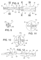
- the piston 4 comprises a stem, having a cross-shaped cross section, formed by a proximal portion 40 and by a distal portion 41 ending in a plunger 42 adapted to slide air-tightly inside the aspiration chamber 23 of the syringe body.
- a circular flange 43 acting as a resting surface for the user's thumb to push the piston 4 forward.
- the proximal portion 40 has four stiff ribs 44 disposed in the form of a "+" in cross section, so as to define a diameter adapted to slide inside the proximal portion 20 of the syringe body.
- One of the ribs 44 has at the end a rib 45 with a greater width, so as to be substantially T-shaped in section.
- the rib with a greater width 45 is adapted to slide in the channel 29 with a greater width of the proximal portion 20 of the syringe body.
- the rib 44, diametrically opposite the rib 45, is of such a thickness as to be able to slide in the channel 30 with a smaller width of the proximal portion 20 of the syringe body.
- a cylindrical tang 46 which extends according to the diameter of the stem, is integrated within two diametrically opposite ribs 44.
- a pin 47 having two ends 47a and 47b protruding from the tang 46 and acting as guide pins or nibs is inserted into the tang 46.
- the ends 47a and 47b of the pin 47 are adapted to slide in the longitudinal channels 27 of the proximal portion of the syringe body.
- the pin 47 is coupled forcibly in the tang 46, after which the piston is inserted into the syringe body and the tang 46 is situated level with the holes 28 at the end of the longitudinal slots 27. Otherwise, if the pin 47 is pre-mounted in the piston 4, the piston must be inserted forcibly into the syringe body, so that the protrusions 47a and 47b of the pin 47 are inserted into the channels 27 of the syringe body. Once the piston has been mounted inside the syringe body, it can no longer be extracted, since the nibs 47a and 47b abut against the end-of-stroke walls 27a of the slots 27.
- the distal part 41 of the piston stem has four ribs 48 crossed in a "+" shape in cross section, with a diameter adapted to slide inside the aspiration chamber 23 of the distal portion of the syringe body.
- the protruding part 45 of the rib 44 of the proximal portion of the stem continues in a flexible tongue 50, which extends above a rib 48 of the distal part of the stem, forming a gap 55 between the flexible tongue 50 and the rib 48.
- a protruding part 51 which defines a tapered entry surface 52 with an acute angle and a tapered exit surface 53 with an obtuse angle.
- the end 54 of the flexible tongue 50 is tapered.
- the flexible tongue 50 is adapted to be inserted in the slot 31 formed in the median transitional portion 2 of the syringe body.
- the spring 8 is of the spiral type and is adapted to be disposed around the distal portion 41 of the piston stem, entering the gap 55 formed by the elastic tongue 50 of the stem. Furthermore, the spring 8 is also inserted into the proximal portion 20 of the syringe body. In this manner, one end of the spring 8 abuts against the end of the ribs 44 and of the tang 46 of the proximal portion 40 of the stem and the other end of the spring 8 abuts against the narrowing that forms the median transitional portion 22 of the syringe body.
- the user initially pushes the piston 4 forwards by pressing with his or her thumb on the proximal flange 43 of the piston and by holding the proximal flange 26 of the syringe body with the index and middle finger.
- the spring 8 is compressed and loaded.
- the flexible tongue 50 of the piston passes through the slot 31 in the tapered median part 22 of the syringe body disposing itself in the gap 33 beneath the flexible tongue 32 of the syringe body.
- the stylet 57 slides inside the needle cannula 60 so that the tip 58 of the stylet exits from the tip 60 of the needle cannula.
- the tapered entry surface 52 of the protrusion 51 of the piston tongue slides beneath the edge of the slot 31, bending the tongue 50 in the gap 55; at the same time the tapered end 54 of the tongue 50 slides on the tapered entry surface 35 of the protrusion 34 beneath the rib 32, thus raising the rib 50.
- the tongue 50 returns elastically into the starting position and the tapered exit surface 53 of the protrusion 51 abuts against the edge of the slot 31, thus retaining the piston 4 in its forward position against the action of the spring 8.
- the plunger 42 is at the end of its stroke in the aspiration chamber 23 and the spring 8 is loaded under compression.
- the user ensures that the stopper 9 is screwed to the connector 36 to close the conduit 37 tightly and inserts the tip 58 of the stylet into the patient's skin.
- the tip 58 of the stylet acts as a guide for the tip 60 of the needle cannula 6 allowing the needle cannula 6 to be inserted until the tip 58 of the stylet perforates the organ on which the biopsy is to be done.
- the flexible tongue 32 of the syringe body presses the protrusion 51 of the flexible tongue 50 of the piston, until the tapered exit surface 53 of the protrusion 51 no longer interferes with the edge of the slot 31 and thus the piston is no longer held in place. Consequently, through the action of the spring 8, which is released, the piston 4 is pushed backwards, until the pins 47a and 47b of the piston abut against the abutment surfaces 27a and 27b of the longitudinal slots 27 of the syringe body.
- a vacuum is created in the aspiration chamber 23.
- the retraction of the piston 4 also causes a retraction of the stylet 57 inside the needle cannula 6.
- the operator causes the needle to make a short excursion into the organ to be biopsied.
- the cells and the fragments of the organ resected by the tip 60 of the needle cannula are aspirated into the needle cannula 6, into the space freed by the stylet 57, and also in part into the aspiration chamber 23.
- the user extracts the needle cannula 6 from the patient and places the tip 60 of the needle cannula in a test tube for collecting the material sampled, then pushes the piston 4 forward. Consequently the stylet 57 slides forward inside the needle cannula 6 to push the sampled material out of the needle cannula 6 into the test tube.
- Said fluid supply source can be a standard syringe provided with a tip adapted to couple with the connector 36 or can be any other medical device provided with a Luer type connector.
- a fluid suitable for biopsy analyses such as for example the Saccomanno's fluid, is made to flow in through the conduit 37.
- This fluid passes through the hole 38 and enters the aspiration chamber 23, to flow outward through the needle cannula 6 and the conduit 37.
- the fluid performs a perfect flushing of the aspiration chamber 23 and of the inside of the needle cannula 6, carrying with it all the sampled cells and fragments.
Landscapes
- Health & Medical Sciences (AREA)
- Life Sciences & Earth Sciences (AREA)
- Medical Informatics (AREA)
- Engineering & Computer Science (AREA)
- Biomedical Technology (AREA)
- Heart & Thoracic Surgery (AREA)
- Pathology (AREA)
- Molecular Biology (AREA)
- Surgery (AREA)
- Animal Behavior & Ethology (AREA)
- General Health & Medical Sciences (AREA)
- Public Health (AREA)
- Veterinary Medicine (AREA)
- Infusion, Injection, And Reservoir Apparatuses (AREA)
Priority Applications (2)
| Application Number | Priority Date | Filing Date | Title |
|---|---|---|---|
| EP08425011A EP2078496B1 (de) | 2008-01-09 | 2008-01-09 | Biopsievorrichtung und Verfahren zur Wiedergewinnung von damit getestetem organischem Material |
| US12/346,102 US20090177115A1 (en) | 2008-01-09 | 2008-12-30 | Biopsy device and method for the recovery of organic material sampled therewith |
Applications Claiming Priority (1)
| Application Number | Priority Date | Filing Date | Title |
|---|---|---|---|
| EP08425011A EP2078496B1 (de) | 2008-01-09 | 2008-01-09 | Biopsievorrichtung und Verfahren zur Wiedergewinnung von damit getestetem organischem Material |
Publications (2)
| Publication Number | Publication Date |
|---|---|
| EP2078496A1 true EP2078496A1 (de) | 2009-07-15 |
| EP2078496B1 EP2078496B1 (de) | 2012-05-16 |
Family
ID=39650606
Family Applications (1)
| Application Number | Title | Priority Date | Filing Date |
|---|---|---|---|
| EP08425011A Not-in-force EP2078496B1 (de) | 2008-01-09 | 2008-01-09 | Biopsievorrichtung und Verfahren zur Wiedergewinnung von damit getestetem organischem Material |
Country Status (2)
| Country | Link |
|---|---|
| US (1) | US20090177115A1 (de) |
| EP (1) | EP2078496B1 (de) |
Cited By (1)
| Publication number | Priority date | Publication date | Assignee | Title |
|---|---|---|---|---|
| US9943293B2 (en) | 2011-11-09 | 2018-04-17 | Teesuvac Aps | Handheld tissue sample extraction device |
Families Citing this family (5)
| Publication number | Priority date | Publication date | Assignee | Title |
|---|---|---|---|---|
| US20180153528A1 (en) * | 2015-06-04 | 2018-06-07 | University Of Florida Research Foundation, Inc. | Coaxial biopsy needles |
| IT201700005840A1 (it) * | 2017-01-19 | 2018-07-19 | Roberto Zambelli | Dispositivo per biopsia di tessuti molli e metodo per il recupero del materiale organico prelevato |
| EP4234085B1 (de) * | 2018-08-17 | 2026-02-25 | Becton, Dickinson and Company | System zum sammeln von biologischen flüssigkeiten |
| CN113243939B (zh) * | 2021-05-17 | 2022-11-22 | 焦淑静 | 一种妇产科羊水取样临床检测装置 |
| US20240081793A1 (en) * | 2022-09-12 | 2024-03-14 | Sean Lyman | Fine needle aspiration (fna) syringe assemblies and methods of using the same |
Citations (6)
| Publication number | Priority date | Publication date | Assignee | Title |
|---|---|---|---|---|
| EP0173653A2 (de) | 1984-07-31 | 1986-03-05 | Roberto Zambelli | Vorrichtung zur Durchführung von Biopsien |
| GB2256369A (en) * | 1991-06-04 | 1992-12-09 | Chiou Rei Kwen | Negative pressure biopsy needle |
| US5246011A (en) * | 1992-01-30 | 1993-09-21 | Caillouette James C | Fine needle aspiration syringe |
| US5320110A (en) * | 1991-10-29 | 1994-06-14 | Wang Ko P | Pleural biopsy syringe-needles |
| US5713368A (en) * | 1990-02-28 | 1998-02-03 | Medical Device Technologies, Inc. | Single use automated soft tissue aspiration biopsy device |
| US6413228B1 (en) * | 1998-12-28 | 2002-07-02 | Pro Duct Health, Inc. | Devices, methods and systems for collecting material from a breast duct |
Family Cites Families (4)
| Publication number | Priority date | Publication date | Assignee | Title |
|---|---|---|---|---|
| US4793363A (en) * | 1986-09-11 | 1988-12-27 | Sherwood Medical Company | Biopsy needle |
| US5843023A (en) * | 1995-10-04 | 1998-12-01 | Cecchi; Michael | Aspiration needle with side port |
| IL140494A0 (en) * | 2000-12-22 | 2002-02-10 | Pneumatic control system for a biopsy device | |
| US7169114B2 (en) * | 2003-06-04 | 2007-01-30 | Krause William R | Biopsy and delivery device |
-
2008
- 2008-01-09 EP EP08425011A patent/EP2078496B1/de not_active Not-in-force
- 2008-12-30 US US12/346,102 patent/US20090177115A1/en not_active Abandoned
Patent Citations (6)
| Publication number | Priority date | Publication date | Assignee | Title |
|---|---|---|---|---|
| EP0173653A2 (de) | 1984-07-31 | 1986-03-05 | Roberto Zambelli | Vorrichtung zur Durchführung von Biopsien |
| US5713368A (en) * | 1990-02-28 | 1998-02-03 | Medical Device Technologies, Inc. | Single use automated soft tissue aspiration biopsy device |
| GB2256369A (en) * | 1991-06-04 | 1992-12-09 | Chiou Rei Kwen | Negative pressure biopsy needle |
| US5320110A (en) * | 1991-10-29 | 1994-06-14 | Wang Ko P | Pleural biopsy syringe-needles |
| US5246011A (en) * | 1992-01-30 | 1993-09-21 | Caillouette James C | Fine needle aspiration syringe |
| US6413228B1 (en) * | 1998-12-28 | 2002-07-02 | Pro Duct Health, Inc. | Devices, methods and systems for collecting material from a breast duct |
Cited By (2)
| Publication number | Priority date | Publication date | Assignee | Title |
|---|---|---|---|---|
| US9943293B2 (en) | 2011-11-09 | 2018-04-17 | Teesuvac Aps | Handheld tissue sample extraction device |
| US11026665B2 (en) | 2011-11-09 | 2021-06-08 | Teesuvac Aps | Handheld tissue sample extraction device |
Also Published As
| Publication number | Publication date |
|---|---|
| EP2078496B1 (de) | 2012-05-16 |
| US20090177115A1 (en) | 2009-07-09 |
Similar Documents
| Publication | Publication Date | Title |
|---|---|---|
| US8419687B2 (en) | Device for shielding a sharp tip of a cannula and method of using the same | |
| US5511556A (en) | Needle core biopsy instrument | |
| US8439846B2 (en) | Bone biopsy device | |
| US5651372A (en) | Biopsy syringe | |
| EP2078496B1 (de) | Biopsievorrichtung und Verfahren zur Wiedergewinnung von damit getestetem organischem Material | |
| JP5379249B2 (ja) | 組織採取装置 | |
| CN109069133B (zh) | 活检注射器 | |
| CN105377147B (zh) | 真空辅助手持活检装置 | |
| US20150005662A1 (en) | System and method for fine needle aspiration | |
| JP3661470B2 (ja) | 組織採取装置 | |
| CN108095774B (zh) | 改进的骨骼活组织检查装置 | |
| US20190090862A1 (en) | Anchor needle | |
| EP1905361A1 (de) | Punktionsnadel für endoskop und verfahren zur entnahme von gewebe aus einer zielregion mit der punktionsnadel für ein endoskop | |
| JP2008538713A (ja) | 導入器、針保護具および採血システムを備えたカニューレ | |
| CN103284762A (zh) | 对器官进行取样的装置 | |
| IT201700005840A1 (it) | Dispositivo per biopsia di tessuti molli e metodo per il recupero del materiale organico prelevato | |
| CN119212630A (zh) | 阀组件 | |
| CN107530066A (zh) | 多重抽样活检装置 | |
| HK40007418A (en) | Biopsy syringe | |
| HK1093928A (en) | Device for shielding a sharp tip of a cannula and method of using the same | |
| HK40007418B (zh) | 活检注射器 |
Legal Events
| Date | Code | Title | Description |
|---|---|---|---|
| PUAI | Public reference made under article 153(3) epc to a published international application that has entered the european phase |
Free format text: ORIGINAL CODE: 0009012 |
|
| AK | Designated contracting states |
Kind code of ref document: A1 Designated state(s): AT BE BG CH CY CZ DE DK EE ES FI FR GB GR HR HU IE IS IT LI LT LU LV MC MT NL NO PL PT RO SE SI SK TR |
|
| AX | Request for extension of the european patent |
Extension state: AL BA MK RS |
|
| 17P | Request for examination filed |
Effective date: 20100111 |
|
| AKX | Designation fees paid |
Designated state(s): AT BE BG CH CY CZ DE DK EE ES FI FR GB GR HR HU IE IS IT LI LT LU LV MC MT NL NO PL PT RO SE SI SK TR |
|
| 17Q | First examination report despatched |
Effective date: 20101108 |
|
| GRAP | Despatch of communication of intention to grant a patent |
Free format text: ORIGINAL CODE: EPIDOSNIGR1 |
|
| GRAS | Grant fee paid |
Free format text: ORIGINAL CODE: EPIDOSNIGR3 |
|
| GRAA | (expected) grant |
Free format text: ORIGINAL CODE: 0009210 |
|
| AK | Designated contracting states |
Kind code of ref document: B1 Designated state(s): AT BE BG CH CY CZ DE DK EE ES FI FR GB GR HR HU IE IS IT LI LT LU LV MC MT NL NO PL PT RO SE SI SK TR |
|
| REG | Reference to a national code |
Ref country code: GB Ref legal event code: FG4D |
|
| REG | Reference to a national code |
Ref country code: CH Ref legal event code: EP |
|
| REG | Reference to a national code |
Ref country code: AT Ref legal event code: REF Ref document number: 557656 Country of ref document: AT Kind code of ref document: T Effective date: 20120615 |
|
| REG | Reference to a national code |
Ref country code: IE Ref legal event code: FG4D |
|
| REG | Reference to a national code |
Ref country code: DE Ref legal event code: R096 Ref document number: 602008015597 Country of ref document: DE Effective date: 20120719 |
|
| REG | Reference to a national code |
Ref country code: NL Ref legal event code: VDEP Effective date: 20120516 |
|
| REG | Reference to a national code |
Ref country code: LT Ref legal event code: MG4D Effective date: 20120516 |
|
| PG25 | Lapsed in a contracting state [announced via postgrant information from national office to epo] |
Ref country code: PL Free format text: LAPSE BECAUSE OF FAILURE TO SUBMIT A TRANSLATION OF THE DESCRIPTION OR TO PAY THE FEE WITHIN THE PRESCRIBED TIME-LIMIT Effective date: 20120516 Ref country code: FI Free format text: LAPSE BECAUSE OF FAILURE TO SUBMIT A TRANSLATION OF THE DESCRIPTION OR TO PAY THE FEE WITHIN THE PRESCRIBED TIME-LIMIT Effective date: 20120516 Ref country code: IS Free format text: LAPSE BECAUSE OF FAILURE TO SUBMIT A TRANSLATION OF THE DESCRIPTION OR TO PAY THE FEE WITHIN THE PRESCRIBED TIME-LIMIT Effective date: 20120916 Ref country code: NO Free format text: LAPSE BECAUSE OF FAILURE TO SUBMIT A TRANSLATION OF THE DESCRIPTION OR TO PAY THE FEE WITHIN THE PRESCRIBED TIME-LIMIT Effective date: 20120816 Ref country code: LT Free format text: LAPSE BECAUSE OF FAILURE TO SUBMIT A TRANSLATION OF THE DESCRIPTION OR TO PAY THE FEE WITHIN THE PRESCRIBED TIME-LIMIT Effective date: 20120516 Ref country code: CY Free format text: LAPSE BECAUSE OF FAILURE TO SUBMIT A TRANSLATION OF THE DESCRIPTION OR TO PAY THE FEE WITHIN THE PRESCRIBED TIME-LIMIT Effective date: 20120516 Ref country code: SE Free format text: LAPSE BECAUSE OF FAILURE TO SUBMIT A TRANSLATION OF THE DESCRIPTION OR TO PAY THE FEE WITHIN THE PRESCRIBED TIME-LIMIT Effective date: 20120516 |
|
| REG | Reference to a national code |
Ref country code: AT Ref legal event code: MK05 Ref document number: 557656 Country of ref document: AT Kind code of ref document: T Effective date: 20120516 |
|
| PG25 | Lapsed in a contracting state [announced via postgrant information from national office to epo] |
Ref country code: HR Free format text: LAPSE BECAUSE OF FAILURE TO SUBMIT A TRANSLATION OF THE DESCRIPTION OR TO PAY THE FEE WITHIN THE PRESCRIBED TIME-LIMIT Effective date: 20120516 Ref country code: SI Free format text: LAPSE BECAUSE OF FAILURE TO SUBMIT A TRANSLATION OF THE DESCRIPTION OR TO PAY THE FEE WITHIN THE PRESCRIBED TIME-LIMIT Effective date: 20120516 Ref country code: GR Free format text: LAPSE BECAUSE OF FAILURE TO SUBMIT A TRANSLATION OF THE DESCRIPTION OR TO PAY THE FEE WITHIN THE PRESCRIBED TIME-LIMIT Effective date: 20120817 Ref country code: PT Free format text: LAPSE BECAUSE OF FAILURE TO SUBMIT A TRANSLATION OF THE DESCRIPTION OR TO PAY THE FEE WITHIN THE PRESCRIBED TIME-LIMIT Effective date: 20120917 Ref country code: LV Free format text: LAPSE BECAUSE OF FAILURE TO SUBMIT A TRANSLATION OF THE DESCRIPTION OR TO PAY THE FEE WITHIN THE PRESCRIBED TIME-LIMIT Effective date: 20120516 |
|
| PG25 | Lapsed in a contracting state [announced via postgrant information from national office to epo] |
Ref country code: BE Free format text: LAPSE BECAUSE OF FAILURE TO SUBMIT A TRANSLATION OF THE DESCRIPTION OR TO PAY THE FEE WITHIN THE PRESCRIBED TIME-LIMIT Effective date: 20120516 |
|
| PG25 | Lapsed in a contracting state [announced via postgrant information from national office to epo] |
Ref country code: DK Free format text: LAPSE BECAUSE OF FAILURE TO SUBMIT A TRANSLATION OF THE DESCRIPTION OR TO PAY THE FEE WITHIN THE PRESCRIBED TIME-LIMIT Effective date: 20120516 Ref country code: AT Free format text: LAPSE BECAUSE OF FAILURE TO SUBMIT A TRANSLATION OF THE DESCRIPTION OR TO PAY THE FEE WITHIN THE PRESCRIBED TIME-LIMIT Effective date: 20120516 Ref country code: EE Free format text: LAPSE BECAUSE OF FAILURE TO SUBMIT A TRANSLATION OF THE DESCRIPTION OR TO PAY THE FEE WITHIN THE PRESCRIBED TIME-LIMIT Effective date: 20120516 Ref country code: NL Free format text: LAPSE BECAUSE OF FAILURE TO SUBMIT A TRANSLATION OF THE DESCRIPTION OR TO PAY THE FEE WITHIN THE PRESCRIBED TIME-LIMIT Effective date: 20120516 Ref country code: RO Free format text: LAPSE BECAUSE OF FAILURE TO SUBMIT A TRANSLATION OF THE DESCRIPTION OR TO PAY THE FEE WITHIN THE PRESCRIBED TIME-LIMIT Effective date: 20120516 Ref country code: CZ Free format text: LAPSE BECAUSE OF FAILURE TO SUBMIT A TRANSLATION OF THE DESCRIPTION OR TO PAY THE FEE WITHIN THE PRESCRIBED TIME-LIMIT Effective date: 20120516 Ref country code: SK Free format text: LAPSE BECAUSE OF FAILURE TO SUBMIT A TRANSLATION OF THE DESCRIPTION OR TO PAY THE FEE WITHIN THE PRESCRIBED TIME-LIMIT Effective date: 20120516 |
|
| PLBE | No opposition filed within time limit |
Free format text: ORIGINAL CODE: 0009261 |
|
| STAA | Information on the status of an ep patent application or granted ep patent |
Free format text: STATUS: NO OPPOSITION FILED WITHIN TIME LIMIT |
|
| 26N | No opposition filed |
Effective date: 20130219 |
|
| PG25 | Lapsed in a contracting state [announced via postgrant information from national office to epo] |
Ref country code: ES Free format text: LAPSE BECAUSE OF FAILURE TO SUBMIT A TRANSLATION OF THE DESCRIPTION OR TO PAY THE FEE WITHIN THE PRESCRIBED TIME-LIMIT Effective date: 20120827 |
|
| PGFP | Annual fee paid to national office [announced via postgrant information from national office to epo] |
Ref country code: GB Payment date: 20130123 Year of fee payment: 6 Ref country code: DE Payment date: 20130130 Year of fee payment: 6 Ref country code: FR Payment date: 20130218 Year of fee payment: 6 |
|
| REG | Reference to a national code |
Ref country code: DE Ref legal event code: R097 Ref document number: 602008015597 Country of ref document: DE Effective date: 20130219 |
|
| PG25 | Lapsed in a contracting state [announced via postgrant information from national office to epo] |
Ref country code: BG Free format text: LAPSE BECAUSE OF FAILURE TO SUBMIT A TRANSLATION OF THE DESCRIPTION OR TO PAY THE FEE WITHIN THE PRESCRIBED TIME-LIMIT Effective date: 20120816 |
|
| PG25 | Lapsed in a contracting state [announced via postgrant information from national office to epo] |
Ref country code: MC Free format text: LAPSE BECAUSE OF NON-PAYMENT OF DUE FEES Effective date: 20130131 |
|
| REG | Reference to a national code |
Ref country code: CH Ref legal event code: PL |
|
| REG | Reference to a national code |
Ref country code: IE Ref legal event code: MM4A |
|
| PG25 | Lapsed in a contracting state [announced via postgrant information from national office to epo] |
Ref country code: LI Free format text: LAPSE BECAUSE OF NON-PAYMENT OF DUE FEES Effective date: 20130131 Ref country code: CH Free format text: LAPSE BECAUSE OF NON-PAYMENT OF DUE FEES Effective date: 20130131 |
|
| PG25 | Lapsed in a contracting state [announced via postgrant information from national office to epo] |
Ref country code: IE Free format text: LAPSE BECAUSE OF NON-PAYMENT OF DUE FEES Effective date: 20130109 |
|
| PGFP | Annual fee paid to national office [announced via postgrant information from national office to epo] |
Ref country code: IT Payment date: 20140131 Year of fee payment: 7 |
|
| PG25 | Lapsed in a contracting state [announced via postgrant information from national office to epo] |
Ref country code: MT Free format text: LAPSE BECAUSE OF FAILURE TO SUBMIT A TRANSLATION OF THE DESCRIPTION OR TO PAY THE FEE WITHIN THE PRESCRIBED TIME-LIMIT Effective date: 20120516 |
|
| REG | Reference to a national code |
Ref country code: DE Ref legal event code: R119 Ref document number: 602008015597 Country of ref document: DE |
|
| GBPC | Gb: european patent ceased through non-payment of renewal fee |
Effective date: 20140109 |
|
| REG | Reference to a national code |
Ref country code: DE Ref legal event code: R119 Ref document number: 602008015597 Country of ref document: DE Effective date: 20140801 |
|
| PG25 | Lapsed in a contracting state [announced via postgrant information from national office to epo] |
Ref country code: DE Free format text: LAPSE BECAUSE OF NON-PAYMENT OF DUE FEES Effective date: 20140801 |
|
| REG | Reference to a national code |
Ref country code: FR Ref legal event code: ST Effective date: 20140930 |
|
| PG25 | Lapsed in a contracting state [announced via postgrant information from national office to epo] |
Ref country code: FR Free format text: LAPSE BECAUSE OF NON-PAYMENT OF DUE FEES Effective date: 20140131 Ref country code: GB Free format text: LAPSE BECAUSE OF NON-PAYMENT OF DUE FEES Effective date: 20140109 |
|
| PG25 | Lapsed in a contracting state [announced via postgrant information from national office to epo] |
Ref country code: TR Free format text: LAPSE BECAUSE OF FAILURE TO SUBMIT A TRANSLATION OF THE DESCRIPTION OR TO PAY THE FEE WITHIN THE PRESCRIBED TIME-LIMIT Effective date: 20120516 |
|
| PG25 | Lapsed in a contracting state [announced via postgrant information from national office to epo] |
Ref country code: LU Free format text: LAPSE BECAUSE OF NON-PAYMENT OF DUE FEES Effective date: 20130109 Ref country code: HU Free format text: LAPSE BECAUSE OF FAILURE TO SUBMIT A TRANSLATION OF THE DESCRIPTION OR TO PAY THE FEE WITHIN THE PRESCRIBED TIME-LIMIT; INVALID AB INITIO Effective date: 20080109 |
|
| PG25 | Lapsed in a contracting state [announced via postgrant information from national office to epo] |
Ref country code: IT Free format text: LAPSE BECAUSE OF NON-PAYMENT OF DUE FEES Effective date: 20150109 |