EP2078650A2 - Dispositif de freinage pour un véhicule - Google Patents
Dispositif de freinage pour un véhicule Download PDFInfo
- Publication number
- EP2078650A2 EP2078650A2 EP08019165A EP08019165A EP2078650A2 EP 2078650 A2 EP2078650 A2 EP 2078650A2 EP 08019165 A EP08019165 A EP 08019165A EP 08019165 A EP08019165 A EP 08019165A EP 2078650 A2 EP2078650 A2 EP 2078650A2
- Authority
- EP
- European Patent Office
- Prior art keywords
- vehicle
- brake
- wheel brakes
- brake system
- axle
- Prior art date
- Legal status (The legal status is an assumption and is not a legal conclusion. Google has not performed a legal analysis and makes no representation as to the accuracy of the status listed.)
- Granted
Links
- 230000004044 response Effects 0.000 claims abstract description 33
- 230000000903 blocking effect Effects 0.000 claims description 14
- 239000012530 fluid Substances 0.000 description 5
- 230000008901 benefit Effects 0.000 description 3
- 238000010276 construction Methods 0.000 description 3
- 230000008878 coupling Effects 0.000 description 3
- 238000010168 coupling process Methods 0.000 description 3
- 238000005859 coupling reaction Methods 0.000 description 3
- 238000013461 design Methods 0.000 description 3
- 238000011161 development Methods 0.000 description 3
- 238000009434 installation Methods 0.000 description 3
- 238000012423 maintenance Methods 0.000 description 2
- 238000005096 rolling process Methods 0.000 description 2
- 230000004888 barrier function Effects 0.000 description 1
- 238000009530 blood pressure measurement Methods 0.000 description 1
- 238000004132 cross linking Methods 0.000 description 1
- 230000007423 decrease Effects 0.000 description 1
- 230000001419 dependent effect Effects 0.000 description 1
- 230000001747 exhibiting effect Effects 0.000 description 1
- 230000002349 favourable effect Effects 0.000 description 1
- 230000007257 malfunction Effects 0.000 description 1
- 238000004519 manufacturing process Methods 0.000 description 1
- 238000005259 measurement Methods 0.000 description 1
- 239000012528 membrane Substances 0.000 description 1
- 230000009467 reduction Effects 0.000 description 1
- 238000003860 storage Methods 0.000 description 1
- 230000001960 triggered effect Effects 0.000 description 1
- 238000013022 venting Methods 0.000 description 1
Images


Classifications
-
- B—PERFORMING OPERATIONS; TRANSPORTING
- B60—VEHICLES IN GENERAL
- B60T—VEHICLE BRAKE CONTROL SYSTEMS OR PARTS THEREOF; BRAKE CONTROL SYSTEMS OR PARTS THEREOF, IN GENERAL; ARRANGEMENT OF BRAKING ELEMENTS ON VEHICLES IN GENERAL; PORTABLE DEVICES FOR PREVENTING UNWANTED MOVEMENT OF VEHICLES; VEHICLE MODIFICATIONS TO FACILITATE COOLING OF BRAKES
- B60T13/00—Transmitting braking action from initiating means to ultimate brake actuator with power assistance or drive; Brake systems incorporating such transmitting means, e.g. air-pressure brake systems
- B60T13/10—Transmitting braking action from initiating means to ultimate brake actuator with power assistance or drive; Brake systems incorporating such transmitting means, e.g. air-pressure brake systems with fluid assistance, drive, or release
- B60T13/66—Electrical control in fluid-pressure brake systems
- B60T13/68—Electrical control in fluid-pressure brake systems by electrically-controlled valves
- B60T13/683—Electrical control in fluid-pressure brake systems by electrically-controlled valves in pneumatic systems or parts thereof
-
- B—PERFORMING OPERATIONS; TRANSPORTING
- B60—VEHICLES IN GENERAL
- B60T—VEHICLE BRAKE CONTROL SYSTEMS OR PARTS THEREOF; BRAKE CONTROL SYSTEMS OR PARTS THEREOF, IN GENERAL; ARRANGEMENT OF BRAKING ELEMENTS ON VEHICLES IN GENERAL; PORTABLE DEVICES FOR PREVENTING UNWANTED MOVEMENT OF VEHICLES; VEHICLE MODIFICATIONS TO FACILITATE COOLING OF BRAKES
- B60T13/00—Transmitting braking action from initiating means to ultimate brake actuator with power assistance or drive; Brake systems incorporating such transmitting means, e.g. air-pressure brake systems
- B60T13/74—Transmitting braking action from initiating means to ultimate brake actuator with power assistance or drive; Brake systems incorporating such transmitting means, e.g. air-pressure brake systems with electrical assistance or drive
- B60T13/741—Transmitting braking action from initiating means to ultimate brake actuator with power assistance or drive; Brake systems incorporating such transmitting means, e.g. air-pressure brake systems with electrical assistance or drive acting on an ultimate actuator
-
- B—PERFORMING OPERATIONS; TRANSPORTING
- B60—VEHICLES IN GENERAL
- B60T—VEHICLE BRAKE CONTROL SYSTEMS OR PARTS THEREOF; BRAKE CONTROL SYSTEMS OR PARTS THEREOF, IN GENERAL; ARRANGEMENT OF BRAKING ELEMENTS ON VEHICLES IN GENERAL; PORTABLE DEVICES FOR PREVENTING UNWANTED MOVEMENT OF VEHICLES; VEHICLE MODIFICATIONS TO FACILITATE COOLING OF BRAKES
- B60T13/00—Transmitting braking action from initiating means to ultimate brake actuator with power assistance or drive; Brake systems incorporating such transmitting means, e.g. air-pressure brake systems
- B60T13/10—Transmitting braking action from initiating means to ultimate brake actuator with power assistance or drive; Brake systems incorporating such transmitting means, e.g. air-pressure brake systems with fluid assistance, drive, or release
- B60T13/58—Combined or convertible systems
Definitions
- the invention relates to a brake system according to the preamble of claim 1.
- Such known brake systems are designed as hybrid brake systems for braking a vehicle.
- the apply powers for actuating wheel brakes of the vehicle are provided in two ways. Wheel brakes on at least one first axis of the vehicle have pressure-medium-operated brake cylinders. About this brake cylinder, the wheel brakes are actuated on this first axis of the vehicle, so that the application energies are provided in this case via a pressure medium.
- the wheel brakes on at least one second axis of the vehicle are exclusively electromechanically actuated, so that the application energies are provided electromechanically to these wheel brakes.
- Conventional electropneumatic and pneumatic brake systems typically provide the apply powers for actuating wheel brakes of a vehicle in a single manner.
- the brake cylinders for actuating the wheel brakes are all actuatable electropneumatically or pneumatically.
- a pneumatic pressure can be controlled and, if necessary, a brake request signal can be generated.
- a pressure can be controlled by means of a valve unit.
- An actuated pressure can be amplified by means of relay valves and provided to the pneumatic brake cylinders for actuating the wheel brake.
- conventional electropneumatic or pneumatic brake systems generally have two compressed-air-operated brake circuits, each of which can be supplied with compressed air from a compressed-air reservoir.
- the compressed air reservoirs are connected via compressed air lines with the valve unit and the pneumatic brake cylinders.
- a parking brake is regularly inserted in at least one rear axle of the vehicle in these known service brake systems.
- the brake cylinder on wheel brakes on this rear axle spring accumulator In the unventilated State of the spring brake cylinder, the parking brake is inserted by means of the spring accumulator.
- the parking brake For driving, the parking brake must be released.
- the spring accumulator part of the spring brake cylinder can be acted upon with compressed air by a connection with one of the compressed air reservoir of the vehicle is produced.
- Hybrid systems are less expensive than conventional hydraulic or pneumatic brake systems. Namely, hybrid systems have at least one axle of the vehicle comparatively inexpensive electromechanical brake actuators waiving comparatively more expensive pressure-medium-operated brake cylinder. Such trained as a hybrid system brake system is off JP 2002-067909 known.
- the brake system of JP 2002-067909 has hydraulically actuable brake cylinders on a first group of wheels and electromechanical brake actuators on a second group of wheels.
- the wheels of the first group are regularly wheels of a front axle, while the wheels of the second group are regularly wheels of a rear axle.
- the hydraulic pressure which can be triggered by means of a pedal device can be amplified by means of valve units and can be supplied to hydraulically operated brake cylinders.
- the pressure in the hydraulic brake circuits is measured.
- sensors detect wheel rotational speeds and torques of motors of electromechanical brake actuators.
- the electromechanical brake actuators are controlled.
- To control the electromechanical brake actuator for the left rear wheel serves the measured value of the controlled hydraulic pressure of the right front wheel.
- the controlled hydraulic pressure for the hydraulically actuated wheel brake of the left front wheel serves at the same time to control the electromechanical brake actuator for the right rear wheel.
- the electromechanically actuated wheel brakes are in accordance with JP 2002-067909 not actuated when the vehicle is at a very low speed, when the vehicle is stationary or when a parking function of the vehicle is activated. As a result, electrical energy is saved.
- DE 196 22 017 A1 and EP 1 785 324 A1 show hybrid brake systems having hydraulically actuated brake cylinder for braking wheels on at least one axle of a vehicle and electromechanical brake actuators on at least one second axis of the vehicle.
- JP 2002-067909 also proposes to use the abovementioned braking system designed as a hybrid system also for a vehicle train consisting of a towing vehicle and a trailer vehicle.
- This is largely unproblematic if the trailer vehicle via electromechanically actuated Brake actuators features.
- many trailers have pressure-medium operated brake cylinders.
- a towing vehicle should therefore be able to form a vehicle train with a trailer vehicle, which has pressure-medium-operated brake cylinder and can brake it safely.
- a limitation on the use of trailer vehicles with only electromechanically actuated brake actuators is not desired in the rule.
- a towing vehicle is supposed to couple different trailers and can form a vehicle train with them.
- hydraulic fluid can escape during coupling or when uncoupling the trailer. Hydraulic fluid pollutes the environment and should therefore be collected and disposed of properly. In addition, a loss of hydraulic fluid must be compensated, i. Hydraulic fluid can be refilled. For one thing, even the hydraulic fluid itself is expensive. On the other hand, however, the associated maintenance is costly.
- the invention is therefore based on the problem to provide a service brake system for braking a vehicle, which is less expensive than known service brake systems and in particular in a towing vehicle can be used to which flexible a trailer with operable by the towing vehicle pressure-medium-operated brake cylinders can be coupled.
- the brake system uses air.
- the pressure-medium-operated brake cylinders are compressed air-operated brake cylinders.
- These air-operated brake cylinders are pneumatically actuated by means of compressed air and are therefore also referred to below as pneumatically actuated brake cylinder, regardless of whether the pneumatic pressure is pneumatically or electropneumatically controlled.
- the brake system according to the invention is therefore flexible for various commercial vehicles used. In particular, it is suitable for use in towing vehicles, to which a trailer can be coupled. However, it can also be used in vehicles to which no trailer can be coupled. For example. It can also be used in buses to which no trailer can be coupled. Namely, it is advantageous to use the same components for different commercial vehicles, regardless of whether a trailer can be coupled to this or whether the possibility of coupling a trailer is dispensed with. Then, namely larger quantities can be produced, thereby reducing the cost of individual components and thus the cost of the brake system as a whole.
- a brake system designed as a hybrid system it is possible to dispense with compressed air-operated brake cylinders on at least one axle of the vehicle. Namely, at least one axle of the vehicle wheel brakes are exclusively electromechanically actuated. Electromechanical brake actuators are less expensive than compressed air operated brake cylinders.
- the brake system according to the invention reduces the number of expensive components installed and saves costs.
- the brake system according to the invention also has a high reliability. Namely, if either the pneumatic actuation type or the electromechanical actuation type of wheel brakes fails, a vehicle can still be braked and brought to a standstill via the respective other type of actuation.
- the brake system according to the invention thus provides a cost-effective and in particular in the commercial vehicle field flexibly deployable brake system.
- the wheel brakes on the at least one first axis of the vehicle on two types of actuation.
- the wheel brakes can be actuated on the at least one first axle of the vehicle by means of the compressed air-operated brake cylinders.
- the wheel brakes can be electromechanically actuated on this first axis of the vehicle.
- the wheel brakes are now actuated by means of both types of actuation together or by means of one of these types of actuation alone.
- the wheel brakes are thus flexibly controllable. In particular, this results in the advantage that in case of failure of one type of actuation, the wheel brakes can still be operated by the other type of actuation. This results in a further safety gain when braking the vehicle.
- the at least one first axle of the vehicle has a parking brake function, in particular when said at least one first axle of the vehicle is a rear axle.
- a parking brake function in particular when said at least one first axle of the vehicle is a rear axle.
- the safety when parking the vehicle increases. A rolling away of the vehicle is then effectively prevented by wheel brakes on several axles of the vehicle. The vehicle can thus be parked on steeper roads without it rolling away.
- Wheel brakes on the at least one first axle of the vehicle preferably have an electromechanically actuated parking brake function.
- a pneumatically actuated parking brake function can thus be dispensed with. This reduces the costs.
- the wheel brakes also have an electromechanically actuatable parking brake function on the at least one second axle of the vehicle, a vehicle, even without a pneumatically actuated parking brake function, can be detected on several axles. This results in a high security when parking the vehicle at the same time low costs.
- the at least one first axle of the vehicle may have a pneumatically actuated parking brake function. About this parking brake function, the vehicle is parked alone or support detectable. Preferably, the at least one first axis of the vehicle is then a rear axle.
- the wheel brakes on the at least one second axle of the vehicle may additionally have a parking brake function. In any case, the use of a pneumatically actuated parking brake function, the safety of a proven system when parking the vehicle, which is possibly increased by the use of an electromechanically actuated parking brake function.
- the wheel brakes on the at least one second axis of the vehicle via an electromechanically actuated parking brake function.
- regular air-operated brake cylinders can be installed there.
- Combined spring brake cylinders are then not needed.
- the cost of the brake system can thus be further reduced.
- the at least one second axle of the vehicle will preferably be a rear axle. However, it can also be a front axle.
- the brake pedal device has a brake value transmitter.
- a brake request signal can be generated directly by the brake value transmitter.
- the electromechanically actuated wheel brakes are now indirectly, namely in response to the brake request signal, operated.
- the pneumatic pressure for actuating the pneumatically actuated wheel brakes is electro-pneumatically, ie indirectly, controlled by a valve unit in response to the brake request signal.
- the pressure in direct response to an actuation of the brake pedal ie directly, pneumatically aussteubar.
- An appropriately trained pneumatic redundancy circuit makes it possible to use a vehicle with the invention Brake system to brake even in case of failure of the vehicle electronics by means of the pneumatically actuated brake cylinder.
- the immediate pneumatic control of the pressure is dispensed with. It is therefore no piping with pressure medium lines in the cab of a brake system according to the invention having vehicle more necessary. This reduces the number of compressed air lines. The risk of pressure loss due to leaking compressed air lines is reduced. The cost of the brake system will be reduced.
- a brake request signal is again generated by means of a brake value transmitter in response to an actuation of the brake pedal.
- a pneumatic pressure is at the same time directly pneumatically controlled.
- the pneumatic pressure for actuating the pneumatically actuated wheel brakes is thus not controlled electropneumatically in response to the operation of the brake pedal.
- an axle modulator is dispensable, which otherwise takes over the electropneumatic control of the pneumatic pressure. This saves costs and at the same time ensures that the pneumatically actuated wheel brakes can still be operated even in the event of a failure of the vehicle electronics.
- the brake system according to the invention is therefore advantageously used in vehicles, which without the ability to control electronic pneumatic pressures, and at the same time always, i. even with a failure of the vehicle electronics, should be able to be braked safely.
- a brake request signal is not directly producible in response to an operation of the brake pedal.
- a pneumatic pressure is controlled in this embodiment of the brake system.
- the pneumatically actuated brake cylinder can be actuated.
- the brake request signal is generated indirectly in this embodiment of the invention.
- the compressed air lines which provide the pneumatically actuated brake cylinders compressed air, namely, now have pressure sensors. These pressure sensors measure the pneumatically controlled pneumatic pressure in these compressed air lines. From a measured value of a pressure sensor, a brake request signal can be generated. In response to such a generated brake request signal, the electromechanically actuable wheel brakes are actuated.
- a single pressure sensor generates a single brake request signal.
- a brake request signal is generated from the measured values of a plurality of pressure sensors.
- a plurality of pressure sensors each generate a brake request signal. All electromechanically actuatable wheel brakes can now be actuated in response to a single brake request signal.
- at least one electromechanically actuable wheel brake can be actuated in response to a first brake request signal and at least one second electromechanically actuatable brake can be actuated in response to a second brake request signal.
- electromechanically operable wheel brakes are actuated in response to brake request signals generated by different pressure sensors.
- both the wheel brakes on the at least one first axle and the wheel brakes on the at least one second axle can be controlled by a common module.
- This module can be integrated in the brake pedal device. However, it can also be installed separately. The combined construction compared to a controllability of the wheel brakes of several modules can be dispensed with signal lines between these modules. In addition, there is a cost savings both in the manufacture of the components as well as the installation due to a lower workload.
- the wheel brakes on at least one first axis of the vehicle which has pneumatically actuated brake cylinder, controllable by a first module.
- the exclusively electromechanically actuated wheel brakes on at least one second axis of the vehicle are controlled by a second module.
- the control of the wheel brakes is thus distributed over two modules. This further increases operational safety. In the event of failure of the electronics on one module, the wheel brakes controlled by the other module remain controllable. Consequently, not all wheel brakes can fail at the same time. In case of failure of a module, a vehicle can be braked controlled with the brake system according to the invention and brought to a standstill.
- the two existing modules are also powered by two batteries with electrical energy.
- a possible reason for a failure of the electronics of a module is namely a failure of the power supply.
- the first module which controls the wheel brakes on the at least one first axle of the vehicle with compressed-air-operated brake cylinders, is structurally integrated in the brake pedal device.
- the combined construction leads to a cost reduction. It accounts namely connecting lines and connecting pipes between the brake pedal device and the first module.
- the assembly costs are reduced due to the combined design. As a result, the cost of installation decreases.
- Electromechanically actuatable wheel brakes preferably have an electromechanical ABS (anti-lock braking system) function, ie an anti-lock function by means of which a wheel brake of a blocking wheel can be automatically released.
- ABS anti-lock braking system
- the brake system has at least one wheel speed sensor, by means of which the blocking of a blocking wheel can be detected.
- no additional ABS valve is needed on electromechanically actuated wheel brakes. It thus accounts for more components. The cost of the system can be reduced without compromising safety.
- the ABS function of a wheel brake from the same module is controllable as the respective wheel brake. If there is a failure of electronics, preferably combined in a module functions coincide. However, no ABS function is required for a failed brake function.
- the combined design thus avoids unnecessary data exchange between different modules without increasing the likelihood of a malfunction of the ABS.
- At least one first axis of the vehicle is a front axle of the vehicle and at least one second axle of the vehicle is a rear axle of the vehicle.
- At least one possibly existing further first axle of the vehicle is a rear axle of the vehicle and at least one possibly existing second axle of the vehicle is a front axle of the vehicle.
- wheel brakes on possibly existing further front axles of the vehicle can namely be dispensed with pneumatically actuated brake cylinder.
- pneumatically actuated brake cylinder On at least one rear axle of the vehicle, there is the advantage that a vehicle with the brake system according to the invention can be braked on at least one front axle and at least one rear axle of the vehicle by means of pneumatically actuable brake cylinder.
- the brake system when the brake system is a pneumatic redundancy circuit
- the vehicle can then be braked both by means of wheel brakes on at least one front axle and by means of wheel brakes on at least one rear axle of the vehicle.
- pneumatically actuated brake cylinder may be formed on the at least one rear axle as a combined spring brake cylinder. Then also a parking brake function by means of at least one further first axis can be produced.
- At least one first axis of the vehicle is a rear axle of the vehicle and at least one second axle of the vehicle is a front axle of the vehicle.
- This embodiment has the advantage that a vehicle having the brake system according to the invention is then pneumatically detectable on wheel brakes of at least one rear axle when the pneumatically actuable brake cylinders are formed on the at least one rear axle as a combined spring brake cylinder.
- At least one possibly existing further first axis of the vehicle is a front axle of the vehicle and at least one possibly existing further second axle of the vehicle is a rear axle of the vehicle.
- this vehicle can therefore be braked with the high braking force which can be provided by pneumatically actuable brake cylinders.
- Further second axles of the vehicle which have exclusively electromechanically actuable wheel brakes, can be further rear axles in order to keep the costs of the brake system low.
- the brake system can be used in a vehicle train consisting of a towing vehicle and a trailer vehicle.
- the vehicle having the brake system according to the invention is then the towing vehicle.
- the vehicle's brake system then provides the trailer vehicle with a supply air pressure and an adjusted pneumatic pressure via two compressed air connections for actuating the wheel brakes of the trailer vehicle.
- wheel brakes of a trailer vehicle generally have pneumatically actuable brake cylinders. To operate this Brake cylinder necessary compressed air is easily provided by the brake system according to the invention, since this brake system anyway uses compressed air as a pressure medium.
- this brake system is also designed as a brake system for a vehicle train.
- the brake system now has a plug-in connection, via which the trailer can be provided with an electrical signal for actuating electromechanically actuatable wheel brakes of the trailer.
- a brake system according to the invention in this embodiment exhibiting vehicle can thus be coupled to a trailer, which has inexpensive electromechanically actuated wheel brakes. These wheel brakes can be actuated by means of the electrical signal.
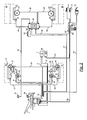
- Fig. 1 schematically shows a first embodiment of the brake system according to the invention with electropneumatically or pneumatically and electromechanically actuated wheel brakes on the front axle of a vehicle and only electromechanically actuated wheel brakes on the rear axle of the vehicle. Shown are primarily the important for understanding the present invention components of the brake system.
- a brake pedal device 1 can be actuated by means of a brake pedal 2.
- a brake request signal can be directly generated by a brake value transmitter 3.
- a valve unit 4 integrated into the brake pedal device 1 in this exemplary embodiment is connected to a compressed air reservoir 7 via compressed air lines 5 and 6.
- the brake system indirectly controls pressure via the valve unit 4.
- the pressure is exclusively electropneumatically by means of this valve unit 4 aussteubar; in another variant, the pressure is exclusive pneumatically actuated by means of the valve unit 4.
- compressed air lines in the driver's cab of the vehicle can be dispensed with.
- the staged pressure is via compressed air lines 8 and 9 an air brake cylinder 10 and via compressed air lines 11 and 12 another air brake cylinder 13 provided.
- By means of the air brake cylinder 10 is a wheel brake 14 for braking a front wheel 15 can be actuated.
- a wheel brake 16 for braking a further front wheel 17 can be actuated.
- a first module 18 is integrated. By means of this module, the brake pressures for the air brake cylinders 10 and 13 are controllable.
- a blocking of the wheels 15 and 17 can be detected by means of the speed sensors 19 and 20. Signals of the rotational speed sensors 19 and 20 can be provided to the first module 18 via electrical lines 21 and 22. When detected blocking a wheel signals to ABS valves 25 and 26 can be transmitted via electrical lines 23 and 24, via which the compressed air lines 9 and 12 and thus the air brake cylinders 10 and 13 are vented. The wheel brakes 14 and 16 are thus solvable when detected blocking a wheel.
- the wheel brakes 14 and 16 are additionally operable for the parking and auxiliary brake functions via electromechanical brake actuators 27 and 28. These electromechanical brake actuators 27 and 28 are connected via electrical lines 29 and 30 to the first module 18 and are controllable by this. An ABS function for the electromechanical brake actuators 27 and 28 is also integrated with the first module 18.
- the brake pedal device 1 and / or the first module 18 can be supplied with electrical energy via an electrical line 31 from a battery, not shown. Furthermore, the brake pedal device 1 has a CAN bus 32 and an electrical line 33, via which the brake pedal device 1 can be connected to a diagnostic device, not shown. By means of the diagnostic device, the brake system can be monitored. By means of a button 34 or any other input device is also a signal for inserting a Barrier generated and by means of an electrical line 35 to the brake pedal device 1 and there integrated first module 18 can be sent.
- the brake pedal device 1 or the first module 18 is connected via an electrical line 37 to a second module 38. Via the electrical line 37 signals are interchangeable.
- the second module 38 via the electrical line 37 a braking request signal from the brake value transmitter 3 can be transmitted.
- Electromechanical brake actuators 41 and 42 of wheel brakes 43 and 44 for braking rear wheels 45 and 46 can be controlled by second module 38 via electrical lines 39 and 40. Consequently, not only the wheel brakes 14 and 16 on at least one first axle of the vehicle but also the wheel brakes 43 and 44 on at least one second axle of the vehicle can be controlled via the electromechanical brake actuators 41 and 42 by means of the brake demand signal generated by the brake value transmitter 3.
- an ABS function for the wheel brakes 43 and 44 is integrated in the second module 38.
- Speeds of the wheels 45 and 46 are detectable by means of speed sensors 47 and 48 and can be transmitted via electrical lines 49 and 50 to the second module 38. If the wheels 45 and 46 are locked, the electromechanical brake actuators 41 and 42 and thus the wheel brakes 43 and 44 are detachable from this second module 38 via the electrical lines 39 and 40.
- an electromechanical parking brake function is provided via the electromechanical brake actuators 41 and 42.
- a request signal for the parking brake function of a parking brake can be generated by means of a pushbutton 51 and can be transmitted to the second module 38 via an electrical line 52.
- the button 51 any other input device can be used.
- the electromechanical brake actuators 41 and 42 for engaging a parking brake on the rear wheels 45 and 46 are actuated upon receipt of a signal from the button 51.
- the parking or auxiliary braking function of the front electromechanical brake actuating device can be requested via the data line 37 from the second module 38 via the first module 18.
- the brake system further comprises a second battery 53, by means of which via an electrical line 54, the second module 38 can be supplied with electrical energy.
- the wheel brakes 43 and 44 are thus actuated independently of the functionality of the first module 18 and / or the battery 34. Even the ABS function for the wheel brakes 43 and 44 of the rear axle is independent of the function of the first module 18.
- the front wheels 15 and 17, as well as the wheels 45 and 46, may each be wheels of an arbitrary axle of a vehicle.
- the wheels 15 and 17 may also be rear wheels and the wheels 45 and 46 may also be front wheels.
- the first module 18 does not have to be integrated into the brake pedal device 1. It is rather a dissolved construction possible. Further, the modules 18 and 38 may also be powered by a single battery or other common power supply of electrical energy. A summarized design of the modules 18 and 38 is possible. Such a summarized module can then be installed separately or structurally integrated into the brake pedal device.
- the electromechanical brake actuators 27 and 28 may be omitted. However, if present, they can provide either an auxiliary braking function, a parking brake function, or both braking functions. About the air brake cylinders 10 and 13, a service brake function is realized.
- the compressed air operated brake cylinders 10 and 13 can also be designed as combined spring / diaphragm brake cylinders. Then ask in addition a parking brake function available.
- the compressed air brake cylinders 10 and 13 then have a membrane part which is pneumatically connected to the service brake system, and a spring storage part, which can be acted upon by separate compressed air lines with compressed air.
- the electromechanical brake actuators 41 and 42 provide at least one service brake function.
- the electro-mechanical brake actuators 41 and 42 may additionally provide a parking brake function.
- a parking brake function is, for example, via one of the types of actuation, i. either realized electromechanically or electropneumatically / pneumatically alone or in a combination of these types of actuation.
- Fig. 1 deviating execution is in direct response to an actuation of the brake pedal 2 pneumatically controlled pressure. With the help of this pressure, the pneumatically actuated brake cylinder of the vehicle are actuated.
- the brake request signal for actuating the electromechanically actuatable wheel brakes of the second axle of the vehicle is in this of Fig. 1 deviant embodiment of signals from pressure sensors, not shown, which are located in the compressed air lines 8 and 11 generated.
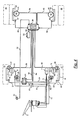
- Fig. 2 schematically shows a second embodiment of the brake system according to the invention for use in a vehicle platoon, consisting of a towing vehicle and a trailer, with electropneumatically actuated wheel brakes on the front axle of the towing vehicle and electromechanically actuated wheel brakes both on the front and on the rear axle of the towing vehicle.
- the components of the brake system which are important for understanding the present invention, are shown as a priority.
- a compressed air reservoir 59 which provides compressed air for a trailer.
- a trailer control valve 60 is connected via a compressed air line 61 to the compressed air reservoir 59.
- An air pressure which is controlled in the valve unit 4 reaches the trailer control valve 60 via a compressed air line 62.
- the trailer control valve 60 furthermore has two connections for electrical lines 63 and 64. Via the electrical line 63, the trailer control valve is electrically connected to the second module 38. Control signals between the second module 38 and the trailer control valve 60 are interchangeable via this electrical line 63.
- the trailer control valve 60 provides the commanded air pressure as well as the supply pressure air via the compressed air connections 71 and 72 to the trailer vehicle.
- a coupled trailer vehicle with pneumatically actuated wheel brakes can be braked via the compressed air provided by these compressed air connections 71 and 72.
- an electrical plug connection 73 which is connected via an electrical line 74 to the first module 18.
- a brake request signal for actuating wheel brakes of the trailer vehicle can be provided to the trailer vehicle via this electrical line 74 and the electrical plug connection 73.
- the towed vehicle may, if it has electromechanically actuable wheel brakes, be braked in response to an electric signal provided via the electrical plug connection 73 via these electromechanical wheel brakes.
- Fig. 3 schematically shows a third embodiment of the brake system according to the invention with pneumatically actuated wheel brakes on the front axle of a vehicle and only electromechanically actuated wheel brakes on the rear axle of the vehicle. Shown are only selected to understand the present invention important components of the brake system.
- the brake pedal device 1 in response to an operation of the brake pedal 2, pneumatically by means of the valve unit 4 directly Pressure controlled.
- Pressure medium is the brake pedal device 1 and the valve unit 4 therein provided from the compressed air reservoir 7 via the compressed air lines 5 and 6.
- the compressed air brake cylinders 10 and 13 With the pneumatic pressure controlled by means of the valve unit 4, the compressed air brake cylinders 10 and 13 are actuated via the compressed air lines 8 and 11.
- These air brake cylinders 10 and 13 actuate the wheel brakes 14 and 16 for braking the front wheels 15 and 17 of the vehicle with the brake system according to the invention.
- the electrical braking request signal is generated indirectly in this embodiment.
- pneumatic pressure can be measured.
- these pressure sensors send electrical signals via electrical lines 83 and 84 to the second module 38.
- These electrical signals are the brake request signals or signals from which one or more brake request signals can be generated by the second module 38 are.
- This second module 38 can be supplied with electrical energy from a battery 53 via an electrical line 54.
- the power supply is thus independent of a power supply for other electrical systems of the vehicle.
- the second module 38 is connected via the electrical line 52 to the button for the parking brake 51.
- the second module 38 controls via the electrical lines 39 and 40, the electromechanical brake actuators 41 and 42 for actuating the wheel brakes 43 and 44 and thus for braking or for fixing the rear wheels 45 and 46 of the vehicle.
- the wheel brakes 14 and 16 are thus actuated directly via the directly pneumatically generated pressure via the air brake cylinders 10 and 13.
- the wheel brakes 43 and 44 indirectly, namely only in response to a measurement of the pneumatic pressure in the compressed air lines 8 and 11 actuated.
- Fig. 4 schematically shows a fourth embodiment of the brake system according to the invention with pneumatically and electromechanically actuated wheel brakes on the front axle of a vehicle and only electromechanically actuated wheel brakes on the rear axle of the vehicle. Shown are above all important for understanding the present invention components of the brake system.
- This embodiment according to Fig. 4 is an extension of the embodiment according to Fig. 3 , Only the features of the brake system important for understanding are described.
- the wheel brakes 14 and 16 for braking the front wheels 15 and 17 not only by means of the air brake cylinders 10 and 13, but also by means of the electromechanical brake actuators 27 and 28 operable.
- the electromechanical brake actuation device 27, 28, 41 and 42 for braking the front wheels 15 and 17 and the rear wheels 45 and 46 are thus all controllable by the second module 38.
- the electromechanical brake actuators 27 and 28 can support the service brake function of the pneumatically actuated air brake cylinders 10 and 13, are used as an alternative to these pneumatically actuated air brake cylinders and / or have a parking brake function.
- Fig. 3 shows the embodiment according to Fig. 4
- an anti-lock system For detecting a locking of the front wheels 15 and 17 and the rear wheels 45 and 46, therefore, the brake system, the speed sensors 19, 20, 47 and 48.
- the speed sensors 47 and 48 are connected via the electrical lines 49 and 50 with the second module 38 connected.
- the blocking of the rear wheel 45 or 46 is thus recognizable by the second module 38.
- the wheel brake 43 or 44 of the blocking rear wheel 45 or 46 can then be released via the electrical line 39 or 40.
- the wheel brake 14 and 16 is in a blocking of the front wheel 15 or 17 solvable.
- the rotational speed information of the rotational speed sensors 19 and 20 are transmitted via the electrical lines 21 and 22 to an ABS (Antilock Braking System) module 91.
- An exchange of data, in particular rotational speed information and / or a recognized blocking of a wheel, between the ABS module 91 and the second module 38 is possible via an electrical line 92.
- the wheel brake 14 and 16 actuated by means of the electromechanical brake actuator 27 and 28, respectively can be engaged by the second module 38 via the electrical leads 29 and 30, respectively, when the front wheel 15 or 17 is blocked by the speed sensor 19 or 20.
- the invention has the ABS module 25 or 26.
- the compressed air lines 8 and 11 thus do not directly connect the valve unit 4 with the compressed air brake cylinders 10 and 13.
- the valve unit 4 is rather via the compressed air lines 8 and 9 and the ABS module 25 with the air brake cylinder 10 and via the compressed air lines 11 and 12 and the ABS -Ventil 26 connected to the air brake cylinder 13.
- the compressed air line 9 or 12 is thus by means of the ABS valve 25 and 26 vented. This venting is made when the blocking of the front wheel 15 or 17 is detected.
- the ABS valves 25 and 26 via the electrical lines 23 and 24 from the ABS module 91 can be controlled.
- ABS module 91 can also be omitted. Then, the functionality of the ABS module 91 is integrated into the second module 38. Alternatively to the second module 38 and the first module 18 may be installed, which is preferably integrated in the brake pedal device 1.
- the invention enables a brake system that manages with only a few expensive air-operated brake cylinders.
- the number of hydraulic lines, valves and ABS valves is reduced compared to conventional brake systems.
- the invention uses electromechanically actuated wheel brakes, realizes a parking brake function as well as an ABS function electromechanically, using electromechanical components that are more favorable than pneumatic components.
Landscapes
- Engineering & Computer Science (AREA)
- Transportation (AREA)
- Mechanical Engineering (AREA)
- Braking Systems And Boosters (AREA)
- Regulating Braking Force (AREA)
Applications Claiming Priority (1)
| Application Number | Priority Date | Filing Date | Title |
|---|---|---|---|
| DE102008003380A DE102008003380A1 (de) | 2008-01-07 | 2008-01-07 | Bremsanlage für ein Fahrzeug |
Publications (4)
| Publication Number | Publication Date |
|---|---|
| EP2078650A2 true EP2078650A2 (fr) | 2009-07-15 |
| EP2078650A3 EP2078650A3 (fr) | 2018-04-18 |
| EP2078650B1 EP2078650B1 (fr) | 2019-04-24 |
| EP2078650B8 EP2078650B8 (fr) | 2019-06-19 |
Family
ID=40674630
Family Applications (1)
| Application Number | Title | Priority Date | Filing Date |
|---|---|---|---|
| EP08019165.3A Not-in-force EP2078650B8 (fr) | 2008-01-07 | 2008-11-03 | Dispositif de freinage pour un véhicule |
Country Status (4)
| Country | Link |
|---|---|
| US (1) | US8702179B2 (fr) |
| EP (1) | EP2078650B8 (fr) |
| JP (1) | JP2009161172A (fr) |
| DE (1) | DE102008003380A1 (fr) |
Cited By (1)
| Publication number | Priority date | Publication date | Assignee | Title |
|---|---|---|---|---|
| WO2017194426A1 (fr) * | 2016-05-09 | 2017-11-16 | Robert Bosch Gmbh | Système de freinage électropneumatique et procédé de montage d'un système de freinage électropneumatique sur un véhicule |
Families Citing this family (16)
| Publication number | Priority date | Publication date | Assignee | Title |
|---|---|---|---|---|
| DE102010021909A1 (de) * | 2010-05-28 | 2011-12-01 | Knorr-Bremse Systeme für Nutzfahrzeuge GmbH | Verfahren zur Steuerung einer Bremsanlage eines Fahrzeugs mit elektronisch geregeltem Hinterachsbremskreis und pneumatisch gesteuertem Vorderachsbremskreis |
| DE102011011634B4 (de) * | 2011-02-17 | 2012-12-06 | Knorr-Bremse Systeme für Nutzfahrzeuge GmbH | Druckluftversorgungseinrichtung für Nutzfahrzeuge |
| PL2570316T5 (pl) | 2011-09-16 | 2023-07-17 | Haldex Brake Products Aktiebolag | Urządzenie eksploatacyjne dla pojazdu szynowego |
| EP2570314B1 (fr) | 2011-09-16 | 2013-12-25 | Haldex Brake Products Aktiebolag | Système de freinage pour un tracteur |
| JP6276430B2 (ja) * | 2014-07-02 | 2018-02-07 | ボルボトラックコーポレーション | 車両の制動システムの操作方法、制動システム、及び同制動システムを備えた車両 |
| DE102014111862A1 (de) * | 2014-08-20 | 2016-02-25 | Knorr-Bremse Systeme für Nutzfahrzeuge GmbH | Hybridbremssystem für ein Fahrzeug und Verfahren zum Ansteuern eines Hybridbremssystems für ein Fahrzeug |
| CN107921942B (zh) * | 2015-07-27 | 2021-06-04 | 沃尔沃卡车集团 | 包括混合制动促动器的制动设备 |
| CN108290557A (zh) * | 2015-09-12 | 2018-07-17 | 通用汽车环球科技运作有限责任公司 | 具有电动驻车制动器的车辆 |
| GB2548102B (en) * | 2016-03-07 | 2018-07-25 | Jaguar Land Rover Ltd | Braking control system |
| US10576946B2 (en) | 2017-02-22 | 2020-03-03 | Arnaldo C. Gomes | Collision avoidance braking system and method |
| US10124777B2 (en) | 2017-02-22 | 2018-11-13 | Arnaldo C. Gomes | Multiple-stage collision avoidance braking system and method |
| DE102017002716A1 (de) * | 2017-03-21 | 2018-09-27 | Wabco Gmbh | Elektronisch steuerbares Bremssystem sowie Verfahren zum Steuern des elektronisch steuerbaren Bremssystems |
| DE102017005980A1 (de) * | 2017-03-21 | 2018-09-27 | Wabco Gmbh | Integriertes Anhängersteuermodul (TCV) mit externer elektropneumatischer Handbremseinheit (EPH) |
| DE102019103901A1 (de) | 2019-02-15 | 2020-08-20 | Wabco Gmbh | Feststellbremsanordnung mit radindividueller ABS-Steuerung |
| DE102023104268A1 (de) * | 2023-02-21 | 2024-08-22 | Zf Cv Systems Global Gmbh | Bremssystem und Verfahren zum Steuern eines Bremssystems |
| CN119734673B (zh) * | 2025-01-02 | 2025-10-31 | 清华大学 | 一种气电复合式车辆制动系统及其控制方法 |
Citations (5)
| Publication number | Priority date | Publication date | Assignee | Title |
|---|---|---|---|---|
| US5390992A (en) | 1993-03-04 | 1995-02-21 | General Motors Corporation | Vehicle electric brake system with static brake torque control |
| DE19622017A1 (de) | 1995-05-31 | 1996-12-05 | Gen Motors Corp | Fahrzeuge |
| JP2002067909A (ja) | 2000-08-29 | 2002-03-08 | Toyota Motor Corp | 車両用ブレーキ装置 |
| EP1352799A2 (fr) | 2002-04-12 | 2003-10-15 | Delphi Technologies, Inc. | Système de freinage hybride d'un véhicule |
| EP1785324A1 (fr) | 2005-11-14 | 2007-05-16 | Delphi Technologies, Inc. | Procédé de controle d'un systeme de freinage hybride |
Family Cites Families (16)
| Publication number | Priority date | Publication date | Assignee | Title |
|---|---|---|---|---|
| DE3410006A1 (de) * | 1984-03-19 | 1985-09-19 | Alfred Teves Gmbh, 6000 Frankfurt | Verfahren zur steuerung einer bremsanlage fuer kraftfahrzeuge und vorrichtung zur durchfuehrung des verfahrens |
| DE4227083C2 (de) * | 1992-08-17 | 2002-06-27 | Knorr Bremse Systeme | Elektronisches Bremssystem, insbesondere für Straßenfahrzeuge |
| FR2705286B1 (fr) * | 1993-05-18 | 1995-09-08 | Smh Management Services Ag | Véhicule comprenant un système de freinage électrique et mécanique. |
| DE19521872B4 (de) * | 1995-06-16 | 2006-03-16 | Knorr-Bremse Systeme für Nutzfahrzeuge GmbH | Verfahren zur Steuerung der Bremsanlage eines Fahrzeugs |
| DE19634567B4 (de) * | 1996-08-27 | 2007-11-29 | Robert Bosch Gmbh | Elektrisches Bremssystem |
| DE19639686A1 (de) * | 1996-09-26 | 1998-04-16 | Siemens Ag | Bremsanlage für ein Kraftfahrzeug |
| DE19940529A1 (de) * | 1999-08-26 | 2001-03-22 | Daimler Chrysler Ag | Bremsvorrichtung, insbesondere für Nutzfahrzeuge |
| JP2002274349A (ja) * | 2001-03-23 | 2002-09-25 | Mitsubishi Motors Corp | 車両の制動装置 |
| DE10219039A1 (de) * | 2002-04-29 | 2003-11-13 | Wabco Gmbh & Co Ohg | Verfahren und Anordnung zur Überwachung von Fahrzeugbremsen elektronisch geregelter Bremssysteme von Fahrzeugen und Fahrzeugkombinationen auf Überlast |
| US7976109B2 (en) * | 2003-01-14 | 2011-07-12 | Bwi Company Limited S.A. | Failsafe operation of a hybrid brake system for a vehicle |
| DE10320608B4 (de) * | 2003-05-08 | 2005-08-11 | Knorr-Bremse Systeme für Nutzfahrzeuge GmbH | Bremsanlage für Fahrzeuge, insbesondere Nutzfahrzeuge mit mindestens zwei separaten elektronischen Bremssteuerkreisen |
| JP2005082122A (ja) * | 2003-09-11 | 2005-03-31 | Hino Motors Ltd | ブレーキ制御装置 |
| DE102005058799A1 (de) * | 2005-12-09 | 2007-06-14 | Wabco Gmbh | Elektropneumatische Bremssteuerungseinrichtung |
| US7497528B2 (en) * | 2006-02-14 | 2009-03-03 | Delphi Technologies, Inc. | Brake-by-wire braking system with hydraulic fail-safe |
| US7798263B2 (en) * | 2006-05-03 | 2010-09-21 | Tandy Engineering & Associates, Inc. | Stability enhancing system for tow-vehicle and trailer assembly combination with two processors |
| US7690735B2 (en) * | 2006-05-12 | 2010-04-06 | Bendix Commercial Vehicle Systems Llc | Service work brake arrangement |
-
2008
- 2008-01-07 DE DE102008003380A patent/DE102008003380A1/de not_active Ceased
- 2008-11-03 EP EP08019165.3A patent/EP2078650B8/fr not_active Not-in-force
- 2008-12-23 US US12/317,704 patent/US8702179B2/en active Active
- 2008-12-25 JP JP2008336203A patent/JP2009161172A/ja active Pending
Patent Citations (5)
| Publication number | Priority date | Publication date | Assignee | Title |
|---|---|---|---|---|
| US5390992A (en) | 1993-03-04 | 1995-02-21 | General Motors Corporation | Vehicle electric brake system with static brake torque control |
| DE19622017A1 (de) | 1995-05-31 | 1996-12-05 | Gen Motors Corp | Fahrzeuge |
| JP2002067909A (ja) | 2000-08-29 | 2002-03-08 | Toyota Motor Corp | 車両用ブレーキ装置 |
| EP1352799A2 (fr) | 2002-04-12 | 2003-10-15 | Delphi Technologies, Inc. | Système de freinage hybride d'un véhicule |
| EP1785324A1 (fr) | 2005-11-14 | 2007-05-16 | Delphi Technologies, Inc. | Procédé de controle d'un systeme de freinage hybride |
Cited By (1)
| Publication number | Priority date | Publication date | Assignee | Title |
|---|---|---|---|---|
| WO2017194426A1 (fr) * | 2016-05-09 | 2017-11-16 | Robert Bosch Gmbh | Système de freinage électropneumatique et procédé de montage d'un système de freinage électropneumatique sur un véhicule |
Also Published As
| Publication number | Publication date |
|---|---|
| US20090189438A1 (en) | 2009-07-30 |
| JP2009161172A (ja) | 2009-07-23 |
| EP2078650B1 (fr) | 2019-04-24 |
| EP2078650A3 (fr) | 2018-04-18 |
| US8702179B2 (en) | 2014-04-22 |
| DE102008003380A1 (de) | 2009-07-09 |
| EP2078650B8 (fr) | 2019-06-19 |
Similar Documents
| Publication | Publication Date | Title |
|---|---|---|
| EP2078650B1 (fr) | Dispositif de freinage pour un véhicule | |
| EP2576297B2 (fr) | Procédé de commande d'un système de freinage d'un véhicule comprenant un circuit de freinage d'essieu arrière à régulation électronique et un circuit de freinage d'essieu avant à commande pneumatique | |
| EP3600991B1 (fr) | Frein à main électro-pneumatique avec tcv integré (commande scandinave) | |
| EP2090481B1 (fr) | Système de freinage à commande électronique doté d'une commande redondante des actionneurs de freinage | |
| EP2244919B1 (fr) | Frein de stationnement pour véhicule, et procédé permettant de faire fonctionner ce frein de stationnement | |
| EP2229302B1 (fr) | Installation de freinage pour un véhicule, et système de pédale de frein pour une telle installation de freinage | |
| EP2942249B2 (fr) | Système de frein entraîné par fluide sous pression pour un véhicule automobile et véhicule automobile associé | |
| DE102008029310B4 (de) | Überwachungseinrichtung zur Überwachung von Systemen eines Fahrzeugs | |
| EP3247596B2 (fr) | Système de freinage électronique pour vehicule | |
| DE102007020881B4 (de) | Elektronisch geregelte Bremsvorrichtung einer Zugfahrzeug-Anhängerkombination | |
| EP3317149B1 (fr) | Dispositif de freinage électrique comprenant un frein de stationnement pouvant être actionné par un élément d'actionnement de frein de service | |
| WO2007065498A1 (fr) | Dispositif electropneumatique de commande de frein | |
| WO2008025401A1 (fr) | Unité de soupape pour dispositif de commande de freinage électropneumatique | |
| DE102010050578A1 (de) | System mit Ventileinrichtung für eine pneumatisch betriebene Bremsanlage, Ventileinrichtung, Bremsbestätigungseinrichtung, Anhängersteuerventileinrichtung und Einrichtung zur Steuerung für das System, Bremsanlage, Fahrzeug, Verwendung einer Komponente und Verfahren zum Umrüsten einer Bremsanlage | |
| DE102019117650A1 (de) | Elektropneumatisches Handbrems-System für Nutzfahrzeuge mit Federspeicher-Feststellbremsen | |
| DE102020106426A1 (de) | Achsmodulator eines Kraftfahrzeugs | |
| DE102022213133A1 (de) | Elektronisch schlupfregelbare Fremdkraftbremsanlage | |
| DE102022128947A1 (de) | Elektro-pneumatische Baueinheit und elektro-pneumatische Bremseinrichtung mit doppelter Redundanz und Bremsschlupfregelung | |
| DE102021102575A1 (de) | Verfahren zum Betreiben eines Steuerungssystems eines Fahrzeugs mit Lenkbremsfunktion und Antriebsschlupfregelung | |
| DE102023134202B3 (de) | Bremsanlage eines Fahrzeugs mit redundanter Parkbremsfunktion |
Legal Events
| Date | Code | Title | Description |
|---|---|---|---|
| PUAI | Public reference made under article 153(3) epc to a published international application that has entered the european phase |
Free format text: ORIGINAL CODE: 0009012 |
|
| AK | Designated contracting states |
Kind code of ref document: A2 Designated state(s): AT BE BG CH CY CZ DE DK EE ES FI FR GB GR HR HU IE IS IT LI LT LU LV MC MT NL NO PL PT RO SE SI SK TR |
|
| AX | Request for extension of the european patent |
Extension state: AL BA MK RS |
|
| PUAL | Search report despatched |
Free format text: ORIGINAL CODE: 0009013 |
|
| AK | Designated contracting states |
Kind code of ref document: A3 Designated state(s): AT BE BG CH CY CZ DE DK EE ES FI FR GB GR HR HU IE IS IT LI LT LU LV MC MT NL NO PL PT RO SE SI SK TR |
|
| AX | Request for extension of the european patent |
Extension state: AL BA MK RS |
|
| RIC1 | Information provided on ipc code assigned before grant |
Ipc: B60T 13/74 20060101ALI20180309BHEP Ipc: B60T 13/68 20060101AFI20180309BHEP |
|
| 17P | Request for examination filed |
Effective date: 20180509 |
|
| RBV | Designated contracting states (corrected) |
Designated state(s): AT BE BG CH CY CZ DE DK EE ES FI FR GB GR HR HU IE IS IT LI LT LU LV MC MT NL NO PL PT RO SE SI SK TR |
|
| 17Q | First examination report despatched |
Effective date: 20180702 |
|
| RBV | Designated contracting states (corrected) |
Designated state(s): AT BE BG CH CY CZ DE DK EE ES FI FR GB GR HR HU IE IS IT LI LT LU LV MC MT NL NO PL PT RO SE SI SK TR |
|
| GRAP | Despatch of communication of intention to grant a patent |
Free format text: ORIGINAL CODE: EPIDOSNIGR1 |
|
| AKX | Designation fees paid |
Designated state(s): DE IT SE |
|
| AXX | Extension fees paid |
Extension state: AL Extension state: BA Extension state: RS Extension state: MK |
|
| INTG | Intention to grant announced |
Effective date: 20181214 |
|
| GRAS | Grant fee paid |
Free format text: ORIGINAL CODE: EPIDOSNIGR3 |
|
| GRAA | (expected) grant |
Free format text: ORIGINAL CODE: 0009210 |
|
| GRAT | Correction requested after decision to grant or after decision to maintain patent in amended form |
Free format text: ORIGINAL CODE: EPIDOSNCDEC |
|
| AK | Designated contracting states |
Kind code of ref document: B1 Designated state(s): DE IT SE |
|
| REG | Reference to a national code |
Ref country code: DE Ref legal event code: R096 Ref document number: 502008016719 Country of ref document: DE |
|
| RAP2 | Party data changed (patent owner data changed or rights of a patent transferred) |
Owner name: WABCO GMBH |
|
| REG | Reference to a national code |
Ref country code: DE Ref legal event code: R081 Ref document number: 502008016719 Country of ref document: DE Owner name: ZF CV SYSTEMS EUROPE BV, BE Free format text: FORMER OWNER: WABCO GMBH & CO. OHG, 30453 HANNOVER, DE Ref country code: DE Ref legal event code: R081 Ref document number: 502008016719 Country of ref document: DE Owner name: ZF CV SYSTEMS HANNOVER GMBH, DE Free format text: FORMER OWNER: WABCO GMBH & CO. OHG, 30453 HANNOVER, DE |
|
| REG | Reference to a national code |
Ref country code: SE Ref legal event code: TRGR |
|
| REG | Reference to a national code |
Ref country code: DE Ref legal event code: R097 Ref document number: 502008016719 Country of ref document: DE |
|
| PLBE | No opposition filed within time limit |
Free format text: ORIGINAL CODE: 0009261 |
|
| STAA | Information on the status of an ep patent application or granted ep patent |
Free format text: STATUS: NO OPPOSITION FILED WITHIN TIME LIMIT |
|
| 26N | No opposition filed |
Effective date: 20200127 |
|
| REG | Reference to a national code |
Ref country code: DE Ref legal event code: R081 Ref document number: 502008016719 Country of ref document: DE Owner name: ZF CV SYSTEMS EUROPE BV, BE Free format text: FORMER OWNER: WABCO GMBH, 30453 HANNOVER, DE Ref country code: DE Ref legal event code: R081 Ref document number: 502008016719 Country of ref document: DE Owner name: ZF CV SYSTEMS HANNOVER GMBH, DE Free format text: FORMER OWNER: WABCO GMBH, 30453 HANNOVER, DE |
|
| PGFP | Annual fee paid to national office [announced via postgrant information from national office to epo] |
Ref country code: SE Payment date: 20211123 Year of fee payment: 14 Ref country code: DE Payment date: 20211130 Year of fee payment: 14 |
|
| PGFP | Annual fee paid to national office [announced via postgrant information from national office to epo] |
Ref country code: IT Payment date: 20211130 Year of fee payment: 14 |
|
| REG | Reference to a national code |
Ref country code: DE Ref legal event code: R081 Ref document number: 502008016719 Country of ref document: DE Owner name: ZF CV SYSTEMS EUROPE BV, BE Free format text: FORMER OWNER: ZF CV SYSTEMS HANNOVER GMBH, 30453 HANNOVER, DE |
|
| REG | Reference to a national code |
Ref country code: DE Ref legal event code: R119 Ref document number: 502008016719 Country of ref document: DE |
|
| REG | Reference to a national code |
Ref country code: SE Ref legal event code: EUG |
|
| PG25 | Lapsed in a contracting state [announced via postgrant information from national office to epo] |
Ref country code: SE Free format text: LAPSE BECAUSE OF NON-PAYMENT OF DUE FEES Effective date: 20221104 |
|
| PG25 | Lapsed in a contracting state [announced via postgrant information from national office to epo] |
Ref country code: IT Free format text: LAPSE BECAUSE OF NON-PAYMENT OF DUE FEES Effective date: 20221103 Ref country code: DE Free format text: LAPSE BECAUSE OF NON-PAYMENT OF DUE FEES Effective date: 20230601 |