EP2078770A2 - Procédé d'opération d'une position de filature d'une machine open-end semi automatique et position de filature destinée à l'exécution du procédé - Google Patents
Procédé d'opération d'une position de filature d'une machine open-end semi automatique et position de filature destinée à l'exécution du procédé Download PDFInfo
- Publication number
- EP2078770A2 EP2078770A2 EP08020815A EP08020815A EP2078770A2 EP 2078770 A2 EP2078770 A2 EP 2078770A2 EP 08020815 A EP08020815 A EP 08020815A EP 08020815 A EP08020815 A EP 08020815A EP 2078770 A2 EP2078770 A2 EP 2078770A2
- Authority
- EP
- European Patent Office
- Prior art keywords
- thread
- workstation
- spinning
- cross
- length
- Prior art date
- Legal status (The legal status is an assumption and is not a legal conclusion. Google has not performed a legal analysis and makes no representation as to the accuracy of the status listed.)
- Granted
Links
Images

Classifications
-
- D—TEXTILES; PAPER
- D01—NATURAL OR MAN-MADE THREADS OR FIBRES; SPINNING
- D01H—SPINNING OR TWISTING
- D01H4/00—Open-end spinning machines or arrangements for imparting twist to independently moving fibres separated from slivers; Piecing arrangements therefor; Covering endless core threads with fibres by open-end spinning techniques
- D01H4/48—Piecing arrangements; Control therefor
- D01H4/50—Piecing arrangements; Control therefor for rotor spinning
-
- D—TEXTILES; PAPER
- D01—NATURAL OR MAN-MADE THREADS OR FIBRES; SPINNING
- D01H—SPINNING OR TWISTING
- D01H4/00—Open-end spinning machines or arrangements for imparting twist to independently moving fibres separated from slivers; Piecing arrangements therefor; Covering endless core threads with fibres by open-end spinning techniques
- D01H4/42—Control of driving or stopping
- D01H4/44—Control of driving or stopping in rotor spinning
Definitions
- the invention relates to a method for operating a workstation of a semi-automatic open-end spinning machine having the features of the preamble of claim 1 or a workstation having the features of the preamble of claim 5.
- Semiautomatic open-end spinning machines are known and, for example in the DE 10 2005 036 485 A1 described in detail. Such textile machines differ from the widely used in the textile industry fully automatic open-end spinning machines, inter alia, in that they have no mobile service unit that supplies the jobs of these textile machines when needed automatically. This means that in semiautomatic open-end spinning machines, operating tasks that were carried out in the case of fully automatic open-end spinning machines by the service unit that can be moved along the work stations are performed manually by the operating personnel. After a yarn breakage or a controlled spinning interruption due to a yarn defect, for example, the yarn end accumulated on the cheese is searched by the operator, cut to length, prepared and introduced for re-spinning in the open-end spinning device. Subsequently, also by the operator, the actual piecing process, which runs automatically, started.
- the unwinding of the thread from the cross-wound bobbin is stopped when such a thread length is sucked into the suction nozzle on the basis of the initially determined erroneous thread length, which ensures that the defective thread length is cut out in the context of the subsequent pneumatic connection of the bobbin-side thread end with a yarn-side end ,
- the present invention seeks to develop a method or a job by which is ensured that at a Spin interruption at a workstation of a semi-automatic open-end spinning machine as a result of a thread error, the operator can easily and safely recognize when the faulty thread length is unwound from the cross-wound bobbin again.
- the spinning process is interrupted at the job concerned in the occurrence of a yarn defect by stopping the sliver feed into the spinning device.
- the single-motor drive of the sliver feed cylinder is simply switched off by the workstation computer and thus the single-fiber feed into the spinning rotor is interrupted.
- the current thread is monitored by a thread cleaner on thread error out and determines the length of the faulty thread that still runs on the cheese, by a workstation, the signals of the thread cleaner and the signals of a sensor of the single motor driven Thread extractor evaluates. That is, by the workstation computer are determined based on the signals of the sensor of the thread take-off both the length of the faulty thread that has accumulated on the cheese, as well as the total thread length of the cheese. From the known yarn parameters and the total yarn length calculates the workstation computer then the current diameter of the cheese, based on which the workstation then determines how often the cheese must be rotated counter to its winding direction to ensure that the faulty thread length is unwound again.
- a sensor device and a signaling device are also connected to the workstation computer.
- the sensor device detects, in particular when the cross-wound bobbin for unwinding the faulty thread is rotated manually counter to the winding direction, the direction and the angular degrees of the rotations of the cross-wound bobbin.
- the signaling device then indicates when the cross-wound bobbin is sufficiently rotated in the unwinding direction, taking into account the respective cross-coil diameter Ensure that the faulty piece of thread is unwound from the cross-wound bobbin and can be separated.
- the jobs for performing the method according to the invention, as described in claim 5, each have a spinning device for producing a yarn, a single-motor driven yarn withdrawal device and a winding device for creating cheeses on.
- the numerous work stations of the semi-automatic open-end spinning machine are each equipped with a signaling device that has a workstation with a thread cleaner for monitoring the running thread, a sensor for determining the withdrawn by the thread withdrawal device from the spinning device thread length and a sensor device, the rotation of the Cross-wound coil recorded, communicating.
- Such equipped workstations not only facilitate the operator's work when eliminating a thread error, because the operator is informed immediately if necessary by the signal device immediately and exactly when the entire faulty thread length is unwound from the cheese, but also allow optimal use of the original material , That is, the lighting up of the signal device upon reaching the unwinding, erroneous thread length results in that it can be easily avoided that unnecessary thread is unwound from the cross-wound bobbin.
- the signal device is integrated in the electronic thread cleaner. Since such thread cleaners are usually anyway equipped with at least one optical display device, for example a colored LED light, it makes sense to use such a LED light as a signaling device which lights up in a predefinable color in the event of an incident.
- optical display device for example a colored LED light
- the sensor device which detects the angle of rotation and the direction of rotation of the cheese in particular during the manual rotation of the cross-wound bobbin, is arranged in the region of the winding device of the work station and preferably has a Hall sensor arranged on the creel and at least one in a rotatable sleeve plate integrated permanent magnet element.
- a Hall sensor arranged on the creel and at least one in a rotatable sleeve plate integrated permanent magnet element.
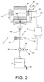
- Fig.1 is in side view and in Fig.2 schematically shown in front view a job 2 a semi-automatic open-end rotor spinning machine 1.
- Such textile machines have, as is known, a plurality of identically formed, in series juxtaposed workstations 2, each having a spinning device 3 and a winding device 33 as essential functional elements.
- a sliver 34 placed in a spinning can 28 is spun into a thread 30, which is then wound on the winding device 33 to form a cross-wound bobbin 22.
- the winding devices 33 have for this purpose, as known per se, a creel 21 for rotatably supporting the sleeve of a cheese 22, a bobbin drive roller 23, a Fadenchangier noticed 26 and a device 7 for lifting the cross-wound bobbin 22 of the bobbin drive roller 23.
- the device 7 is formed, for example, as a thrust piston, which is connected via a pneumatic line to a (not shown) overpressure source and controllable defined.
- the drive of the bobbin drive roller 23 takes place as a group drive. That is, on a machine-length, machine end side driven drive shaft, the bobbin drive rollers 23 of the individual jobs 2 are fixed.
- the spinning device 3 essentially has a spinning rotor 4, a sliver-opening roller 12 and a sliver-intake cylinder 14.
- the spinning rotor 4 is mounted for example in a support disk bearing 5 and is driven by a machine-tangential belt 6.
- the sliver picking roller 12 is acted upon by a machine-tangential belt 13, while the sliver feed cylinder 14 is driven by a motor 15 single motor.
- the drive 15 of the sliver feed cylinder 14, for example a stepper motor, is connected via a control line 16 to a workstation computer 9.
- the work stations 2 each have a thread withdrawal device 18, with a preferably arranged in the region of the drive 19 sensor 32, which is connected via a control line 20 to the workstation computer 9 in connection.
- a thread storage device 37 When viewed in the thread running direction behind the thread withdrawal device 18 is also a thread storage device 37, preferably a pneumatically actuable storage nozzle, is provided, which is connected via a pneumatic line 38 to a (not shown) vacuum source.
- a thread cleaner 11 which monitors the thread 30 produced in the spinning device 3 for thread error out before it is wound onto the cheese 22.
- the thread cleaner 11 is connected via a signal line 24 to the workstation computer 9.
- a signaling device 17 is integrated, which is preferably designed as an LED light.
- a sensor device 25 is arranged in the region of the coil frame 21, which is also connected to the workstation computer 9 via a signal line 31.
- the workstation computer 9 which controls the actuating element of the device 7 for lifting the cross-wound bobbin, the drive 19 of the thread take-off device 18 and the drive 15 of the sliver feed cylinder 14, via a signal line 29 also connected to a switching element 27. That is, the control device 9 can be manually activated by the operating element via the switching element 27.
- the thread 30 is scanned on its way to the cheese 22, which is frictionally driven by a coil drive roller 23, by an electronic thread cleaner 11 and checked for thread error. When running on the cheese, the thread 30 is also traversed by a Fadenchangier issued 26.
- the yarn length produced in the spinning device 3 and wound onto the cross-wound bobbin is determined by means of a sensor 32 which detects angular momentum on the single-motor-driven yarn draw-off device 18.
- the sensor 32 is, as mentioned above, connected via a signal line 20 to the workstation computer 9, which constantly calculated from previously entered Garnparametern and the signals of the sensor 32, the current diameter of the cheese 22.
- the relevant job 2 is stopped by switching off the drive 15 of the sliver feed cylinder 14.
- the length of the faulty thread 30 accumulated on the cross-wound bobbin 22 is determined by the workstation computer 9 on the basis of the signals from the sensor 32 of the thread withdrawal device 18.
- the workstation computer 9 also calculates, based on the actual diameter of the cross-wound bobbin 22, how many degrees of angle the cross-wound bobbin 22 has to be rotated counter to its winding direction to ensure that faulty thread piece is unwound from the cross-wound bobbin 22 again.
- the degrees of angle and the direction of rotation of the cheese 22 are detected by a sensor device 25 arranged in the region of the winding device 33, whose Hall sensor 35 corresponds to at least one permanent magnet 36 arranged in a tube plate of the coil frame 21.
- the signal device 17 is activated by the workstation computer 9. That is, the illumination of a preferably arranged on the thread cleaner 11 LED light reliably indicates to the operator that the faulty thread length is again handled by the cheese 22 and can be cut off.
- the thread end As usual, cut to length on a corresponding device 10, prepared and returned to the spinning device 3.
- the switching element 27 is actuated, which causes the workstation computer 9 to start the piecing process.
Landscapes
- Engineering & Computer Science (AREA)
- Mechanical Engineering (AREA)
- Textile Engineering (AREA)
- Spinning Or Twisting Of Yarns (AREA)
- Spinning Methods And Devices For Manufacturing Artificial Fibers (AREA)
Applications Claiming Priority (1)
| Application Number | Priority Date | Filing Date | Title |
|---|---|---|---|
| DE102008003711A DE102008003711A1 (de) | 2008-01-09 | 2008-01-09 | Verfahren zum Betreiben einer Arbeitsstelle einer semiautomatischen Offenend-Spinnmaschine bzw. Arbeitsstelle zur Durchführung des Verfahrens |
Related Parent Applications (1)
| Application Number | Title | Priority Date | Filing Date |
|---|---|---|---|
| DE102008003711 Previously-Filed-Application | 2008-01-09 |
Publications (3)
| Publication Number | Publication Date |
|---|---|
| EP2078770A2 true EP2078770A2 (fr) | 2009-07-15 |
| EP2078770A3 EP2078770A3 (fr) | 2011-05-11 |
| EP2078770B1 EP2078770B1 (fr) | 2017-07-05 |
Family
ID=40361508
Family Applications (1)
| Application Number | Title | Priority Date | Filing Date |
|---|---|---|---|
| EP08020815.0A Active EP2078770B1 (fr) | 2008-01-09 | 2008-12-01 | Procédé d'opération d'une position de filature d'une machine open-end semi automatique et position de filature destinée à l'exécution du procédé |
Country Status (3)
| Country | Link |
|---|---|
| EP (1) | EP2078770B1 (fr) |
| CN (1) | CN101481838B (fr) |
| DE (1) | DE102008003711A1 (fr) |
Cited By (2)
| Publication number | Priority date | Publication date | Assignee | Title |
|---|---|---|---|---|
| CN102041589A (zh) * | 2009-10-24 | 2011-05-04 | 欧瑞康纺织有限及两合公司 | 用于自由端转子纺纱装置的接头方法 |
| WO2015049293A1 (fr) * | 2013-10-01 | 2015-04-09 | Maschinenfabrik Rieter Ag | Épurateur de fil et poste de filage d'un métier à filer équipé dudit épurateur, ainsi que procédé permettant de faire fonctionner un poste de filage |
Families Citing this family (3)
| Publication number | Priority date | Publication date | Assignee | Title |
|---|---|---|---|---|
| CN102677237B (zh) * | 2012-06-11 | 2014-07-09 | 杭州电子科技大学 | 一种自适应光电式电子清纱器 |
| DE102018112801A1 (de) * | 2018-05-29 | 2019-12-05 | Maschinenfabrik Rieter Ag | Verfahren zum Ermitteln von Eigenschaften eines Fasermaterials an einer Arbeitsstelle einer Textilmaschine und eine Textilmaschine |
| CN111579414B (zh) * | 2020-05-21 | 2022-07-26 | 广东精迅里亚特种线材有限公司 | 一种漆包线分类控制方法和系统 |
Citations (2)
| Publication number | Priority date | Publication date | Assignee | Title |
|---|---|---|---|---|
| DE19640184B4 (de) | 1996-09-30 | 2005-10-13 | Saurer Gmbh & Co. Kg | Verfahren zum Ausreinigen von Garnfehlern an einer Spulstelle einer Spulmaschine |
| DE102005036485A1 (de) | 2005-08-03 | 2007-02-08 | Saurer Gmbh & Co. Kg | Offenend-Rotorspinnmaschine |
Family Cites Families (4)
| Publication number | Priority date | Publication date | Assignee | Title |
|---|---|---|---|---|
| CH668637A5 (de) * | 1984-10-12 | 1989-01-13 | Loepfe Ag Geb | Fadenlaengenmessung. |
| DE19930714C5 (de) * | 1999-07-02 | 2015-04-09 | Rieter Ingolstadt Gmbh | Textilmaschine mit einer Vielzahl gleichartiger Arbeitsstellen |
| CN2498170Y (zh) * | 2001-04-05 | 2002-07-03 | 刘善 | 气流纺纱机粗节纱疵清除器 |
| DE102004013776B4 (de) * | 2004-03-20 | 2017-07-27 | Rieter Ingolstadt Gmbh | Verfahren und Vorrichtung zur Ausreinigung von Garnfehlern |
-
2008
- 2008-01-09 DE DE102008003711A patent/DE102008003711A1/de not_active Withdrawn
- 2008-12-01 EP EP08020815.0A patent/EP2078770B1/fr active Active
- 2008-12-29 CN CN2008101909618A patent/CN101481838B/zh active Active
Patent Citations (2)
| Publication number | Priority date | Publication date | Assignee | Title |
|---|---|---|---|---|
| DE19640184B4 (de) | 1996-09-30 | 2005-10-13 | Saurer Gmbh & Co. Kg | Verfahren zum Ausreinigen von Garnfehlern an einer Spulstelle einer Spulmaschine |
| DE102005036485A1 (de) | 2005-08-03 | 2007-02-08 | Saurer Gmbh & Co. Kg | Offenend-Rotorspinnmaschine |
Cited By (5)
| Publication number | Priority date | Publication date | Assignee | Title |
|---|---|---|---|---|
| CN102041589A (zh) * | 2009-10-24 | 2011-05-04 | 欧瑞康纺织有限及两合公司 | 用于自由端转子纺纱装置的接头方法 |
| CN102041589B (zh) * | 2009-10-24 | 2014-07-30 | 索若德国两合股份有限公司 | 用于自由端转子纺纱装置的接头方法 |
| WO2015049293A1 (fr) * | 2013-10-01 | 2015-04-09 | Maschinenfabrik Rieter Ag | Épurateur de fil et poste de filage d'un métier à filer équipé dudit épurateur, ainsi que procédé permettant de faire fonctionner un poste de filage |
| US20160221790A1 (en) * | 2013-10-01 | 2016-08-04 | Maschinenfabrik Rieter Ag | Yarn Clearer and Spinning Station, Equipped Therewith, of a Spinning Machine, and Method for Operating a Spinning Station |
| US10246292B2 (en) | 2013-10-01 | 2019-04-02 | Maschinenfabrik Rieter Ag | Yarn clearer and spinning station, equipped therewith, of a spinning machine, and method for operating a spinning station |
Also Published As
| Publication number | Publication date |
|---|---|
| CN101481838B (zh) | 2012-10-03 |
| EP2078770A3 (fr) | 2011-05-11 |
| EP2078770B1 (fr) | 2017-07-05 |
| CN101481838A (zh) | 2009-07-15 |
| DE102008003711A1 (de) | 2009-07-16 |
Similar Documents
| Publication | Publication Date | Title |
|---|---|---|
| EP1749906B1 (fr) | Arrangement de rattachement pour une métier à filer à bout libre à rotor | |
| EP2784193B1 (fr) | Poste de filage d'un métier à filer et son procédé de fonctionnement | |
| DE102007048720B4 (de) | Verfahren und Vorrichtung zum Betreiben einer Offenend-Rotorspinnmaschine | |
| EP2918534B1 (fr) | Métier à filer et procédé de transfert d'un fil à un dispositif de rattache | |
| DE102007053467B4 (de) | Verfahren und Vorrichtung zum Betreiben einer Offenend-Rotorspinnmaschine | |
| DE102008003704B4 (de) | Verfahren zum Betreiben einer Arbeitsstelle einer semiautomatischen Offenend-Spinnmaschine bzw. Arbeitsstelle zur Durchführung des Verfahrens | |
| WO2008043408A1 (fr) | Poste de travail d'une machine pour textile | |
| DE102007056561A1 (de) | Kreuzspulen herstellende Textilmaschine | |
| EP2955143B1 (fr) | Machine textile semi-automatique fabriquant des bobines | |
| DE102016109216A1 (de) | Rotorspinnmaschine und Verfahren zur Erneuerung des Spinnvorgangs auf der Arbeitsstelle einer Rotorspinnmaschine | |
| EP2966201A2 (fr) | Métier à tisser à rotor semi-automatique à extrémité ouverte | |
| DE19917968B4 (de) | Serviceaggregat für eine Kreuzspulen herstellende Textilmaschine | |
| EP2078770B1 (fr) | Procédé d'opération d'une position de filature d'une machine open-end semi automatique et position de filature destinée à l'exécution du procédé | |
| DE102007006679B4 (de) | Verfahren zum Betreiben einer Kreuzspulen herstellenden Textilmaschine | |
| EP3241794A1 (fr) | Procédé de manipulation d'une extrémité de fil et poste de bobinage | |
| EP1028080A2 (fr) | Procédé de fonctionnement d'un poste de travail d'une machine textile pour la fabrication de bobines à spires croisées | |
| EP2801544A1 (fr) | Procédé et dispositif de fonctionnement d'un poste de travail d'une machine textile produisant des bobines croisées | |
| WO2008049486A1 (fr) | Procédé et dispositif d'utilisation d'une machine textile qui prépare des bobines croisées | |
| EP2813605A1 (fr) | Procédé de fonctionnement d'un poste de travail d'un métier à filer à rotor à bout libre et poste de travail associé | |
| EP1151951B1 (fr) | Procédé de fonctionnement d'une machine textile pour la fabrication de bobines à spires croisées | |
| EP3581687A1 (fr) | Procédé ou dispositif permettant d'influencer l'état d'enroulement des bobines | |
| EP1225258B1 (fr) | Procédé pour fabriquer des filés de fibres | |
| DE102009033377A1 (de) | Verfahren und Vorrichtung zum Betreiben einer Arbeitsstelle einer Kreuzspulen herstellenden Textilmaschine | |
| EP1828040B1 (fr) | Poste de travail de bobineuse | |
| EP2660376A1 (fr) | Dispositif de fabrication d'une penne permettant la rattache sur un dispositif de tissage à extrémité ouverte |
Legal Events
| Date | Code | Title | Description |
|---|---|---|---|
| PUAI | Public reference made under article 153(3) epc to a published international application that has entered the european phase |
Free format text: ORIGINAL CODE: 0009012 |
|
| AK | Designated contracting states |
Kind code of ref document: A2 Designated state(s): AT BE BG CH CY CZ DE DK EE ES FI FR GB GR HR HU IE IS IT LI LT LU LV MC MT NL NO PL PT RO SE SI SK TR |
|
| AX | Request for extension of the european patent |
Extension state: AL BA MK RS |
|
| PUAL | Search report despatched |
Free format text: ORIGINAL CODE: 0009013 |
|
| AK | Designated contracting states |
Kind code of ref document: A3 Designated state(s): AT BE BG CH CY CZ DE DK EE ES FI FR GB GR HR HU IE IS IT LI LT LU LV MC MT NL NO PL PT RO SE SI SK TR |
|
| AX | Request for extension of the european patent |
Extension state: AL BA MK RS |
|
| 17P | Request for examination filed |
Effective date: 20111111 |
|
| AKX | Designation fees paid |
Designated state(s): DE IT TR |
|
| RAP1 | Party data changed (applicant data changed or rights of an application transferred) |
Owner name: ZHUOLANG TEXTILE MACHINERY CO., LTD. |
|
| 17Q | First examination report despatched |
Effective date: 20160719 |
|
| RAP1 | Party data changed (applicant data changed or rights of an application transferred) |
Owner name: ZHUOLANG INTELLIGENT MACHINERY CO., LTD. |
|
| GRAP | Despatch of communication of intention to grant a patent |
Free format text: ORIGINAL CODE: EPIDOSNIGR1 |
|
| INTG | Intention to grant announced |
Effective date: 20170420 |
|
| RIN1 | Information on inventor provided before grant (corrected) |
Inventor name: SIEWERT, RALF Inventor name: MAC, TAI, DR. |
|
| GRAS | Grant fee paid |
Free format text: ORIGINAL CODE: EPIDOSNIGR3 |
|
| GRAA | (expected) grant |
Free format text: ORIGINAL CODE: 0009210 |
|
| AK | Designated contracting states |
Kind code of ref document: B1 Designated state(s): DE IT TR |
|
| REG | Reference to a national code |
Ref country code: DE Ref legal event code: R096 Ref document number: 502008015426 Country of ref document: DE |
|
| REG | Reference to a national code |
Ref country code: DE Ref legal event code: R097 Ref document number: 502008015426 Country of ref document: DE |
|
| PLBE | No opposition filed within time limit |
Free format text: ORIGINAL CODE: 0009261 |
|
| STAA | Information on the status of an ep patent application or granted ep patent |
Free format text: STATUS: NO OPPOSITION FILED WITHIN TIME LIMIT |
|
| 26N | No opposition filed |
Effective date: 20180406 |
|
| PGFP | Annual fee paid to national office [announced via postgrant information from national office to epo] |
Ref country code: TR Payment date: 20251206 Year of fee payment: 18 |
|
| PGFP | Annual fee paid to national office [announced via postgrant information from national office to epo] |
Ref country code: DE Payment date: 20251222 Year of fee payment: 18 |
|
| PGFP | Annual fee paid to national office [announced via postgrant information from national office to epo] |
Ref country code: IT Payment date: 20251231 Year of fee payment: 18 |