EP2078823B1 - Kühlanordnung für Turbinenbauteile - Google Patents
Kühlanordnung für Turbinenbauteile Download PDFInfo
- Publication number
- EP2078823B1 EP2078823B1 EP09250063.6A EP09250063A EP2078823B1 EP 2078823 B1 EP2078823 B1 EP 2078823B1 EP 09250063 A EP09250063 A EP 09250063A EP 2078823 B1 EP2078823 B1 EP 2078823B1
- Authority
- EP
- European Patent Office
- Prior art keywords
- turbine
- discharge openings
- section
- coolant discharge
- turbine blade
- Prior art date
- Legal status (The legal status is an assumption and is not a legal conclusion. Google has not performed a legal analysis and makes no representation as to the accuracy of the status listed.)
- Ceased
Links
Images
Classifications
-
- F—MECHANICAL ENGINEERING; LIGHTING; HEATING; WEAPONS; BLASTING
- F01—MACHINES OR ENGINES IN GENERAL; ENGINE PLANTS IN GENERAL; STEAM ENGINES
- F01D—NON-POSITIVE DISPLACEMENT MACHINES OR ENGINES, e.g. STEAM TURBINES
- F01D5/00—Blades; Blade-carrying members; Heating, heat-insulating, cooling or antivibration means on the blades or the members
- F01D5/12—Blades
- F01D5/14—Form or construction
- F01D5/18—Hollow blades, i.e. blades with cooling or heating channels or cavities; Heating, heat-insulating or cooling means on blades
- F01D5/186—Film cooling
-
- F—MECHANICAL ENGINEERING; LIGHTING; HEATING; WEAPONS; BLASTING
- F01—MACHINES OR ENGINES IN GENERAL; ENGINE PLANTS IN GENERAL; STEAM ENGINES
- F01D—NON-POSITIVE DISPLACEMENT MACHINES OR ENGINES, e.g. STEAM TURBINES
- F01D5/00—Blades; Blade-carrying members; Heating, heat-insulating, cooling or antivibration means on the blades or the members
- F01D5/12—Blades
- F01D5/14—Form or construction
- F01D5/18—Hollow blades, i.e. blades with cooling or heating channels or cavities; Heating, heat-insulating or cooling means on blades
- F01D5/187—Convection cooling
-
- F—MECHANICAL ENGINEERING; LIGHTING; HEATING; WEAPONS; BLASTING
- F05—INDEXING SCHEMES RELATING TO ENGINES OR PUMPS IN VARIOUS SUBCLASSES OF CLASSES F01-F04
- F05D—INDEXING SCHEME FOR ASPECTS RELATING TO NON-POSITIVE-DISPLACEMENT MACHINES OR ENGINES, GAS-TURBINES OR JET-PROPULSION PLANTS
- F05D2250/00—Geometry
- F05D2250/10—Two-dimensional
- F05D2250/18—Two-dimensional patterned
- F05D2250/185—Two-dimensional patterned serpentine-like
-
- Y—GENERAL TAGGING OF NEW TECHNOLOGICAL DEVELOPMENTS; GENERAL TAGGING OF CROSS-SECTIONAL TECHNOLOGIES SPANNING OVER SEVERAL SECTIONS OF THE IPC; TECHNICAL SUBJECTS COVERED BY FORMER USPC CROSS-REFERENCE ART COLLECTIONS [XRACs] AND DIGESTS
- Y02—TECHNOLOGIES OR APPLICATIONS FOR MITIGATION OR ADAPTATION AGAINST CLIMATE CHANGE
- Y02T—CLIMATE CHANGE MITIGATION TECHNOLOGIES RELATED TO TRANSPORTATION
- Y02T50/00—Aeronautics or air transport
- Y02T50/60—Efficient propulsion technologies, e.g. for aircraft
Definitions
- This disclosure relates to an arrangement of coolant discharge openings of a turbine component used in a gas turbine engine.
- Gas turbine engines are commonly used for propelling an aircraft, for example.
- a conventional gas turbine engine includes a compressor section, a combustion section, and a turbine section having turbine blades and turbine vanes.
- the compressor section compresses air, which is mixed with fuel and burned in the combustion section to produce a hot gas stream that expands in the turbine section.
- the turbine blades and vanes operate within a relatively hot environment.
- the disclosed example turbine components and gas turbine engine include a cooling arrangement that facilitates cooling of the turbine components.
- the turbine component includes coolant discharge openings only in the leading end section, one of the plurality of second intermediate sections, the first intermediate section, and the trailing end section.
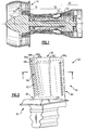
- Figure 1 illustrates selected portions of an example gas turbine engine 10, such as a gas turbine engine 10 used for propulsion.
- the gas turbine engine 10 is circumferentially disposed about an engine centerline 12.
- the engine 10 in this example includes a fan 14, a compressor section 16, a combustion section 18, and a turbine section 20 that includes turbine blades 22 and turbine vanes 24.
- air compressed in the compressor section 16 is mixed with fuel that is burned in the combustion section 18 to produce hot gasses that are expanded in the turbine section 20 to drive the fan 14.
- Figure 1 is a schematic presentation for illustrative purposes only and is not a limitation on the disclosed examples. Additionally, there are various types of gas turbine engines, many of which could benefit from the examples disclosed herein.
- FIGS 2 and 3 illustrate examples of one of the turbine blades 22 shown in Figure 1 . Although the description below is made with reference to the turbine blade 22, it is to be understood that the examples may also be applied to turbine vanes 24.
- the turbine blade 22 includes an airfoil section 34 that extends between a tip 36 and a base 38.
- the airfoil section 34 is secured to a platform section 40 at the base 38.
- the airfoil section 34 includes a leading end 42 (e.g., edge) that is generally oriented forward in the gas turbine engine 10 relative to flow through the gas turbine engine 10, and a trailing end 44 (e.g., edge) that is oriented downstream from the leading end 42.
- the airfoil shape of the airfoil section 34 also includes a pressure side 46 and a suction side 48 that refer to relative pressures created when the hot gas stream from the combustion section 18 flows over the airfoil shape of the airfoil section 34.
- the turbine blade 22 also includes an aft cooling passage 58 (i.e., circuit) and a forward cooling passage 60 (i.e., circuit) for facilitating cooling of the turbine blade 22.
- the cooling passages 58 and 60 are fluidly connected with the compressor section 16 to receive a bleed flow 62 ( Figure 1 ) of relatively cool air that functions as a coolant to internally cool the turbine blade 22 and provide film cooling over the outer surfaces of the turbine blade 22, as will be described below.
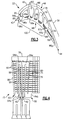
- Figure 4 illustrates a core 72 used to form the turbine blade 22. That is, the turbine blade 22 is formed around the core 72, such as by using a casting technique. Subsequently, the core 72 is removed (e.g., by leaching), leaving the cooling passages 58 and 60 within the turbine blade 22.
- the core 72 represents a solid form of the passages 58 and 60 and is used herein to illustrate the shape of the passages 58 and 60 (e.g., a serpentine shape).
- the aft cooling passage 58 includes a trailing end section 74 that is located near the trailing end 44 of the turbine blade 22, a first interior section 76 that is located near a midsection 78 (e.g., a mid-chord location between the leading end 42 and the trailing end 44) of the turbine blade 22, and a first intermediate section 80 between the trailing end section 74 and the first interior section 76.
- the first interior section 76 functions as an inlet for receiving the bleed flow 62, as represented by arrow 82.
- the first interior section 76 extends lengthwise between the base 38 to the tip 36 of the turbine blade 22 and transitions into the first interior section 76 through turn section 84a.
- the first intermediate section 80 extends lengthwise between the base 38 to the tip 36 from the turn section 84a to another turn section 84b, which provides a transition from the first intermediate section 80 into the trailing end section 74.
- the forward cooling passage 60 also includes several sections.
- a leading end section 86 is located near the leading end 42 of the turbine blade 22
- a second interior section 88 is located near the midsection 78 of the turbine blade 22
- a plurality of second intermediate sections 90 are located between the leading end section 86 and the second interior section 88.
- the second interior section 88 functions as an inlet for receiving the bleed flow 62, as represented by the arrow 92.
- the second interior section 88 generally extends lengthwise between the base 38 to the tip 36 of the turbine blade 22 and transitions into the plurality of second intermediate sections 90 through a turn section 94a.
- the plurality of second intermediate sections 90 also include another turn section 94b.
- the forward one of the second intermediate sections 90 that is located near the leading end 42 of the turbine blade 22 is also connected with the leading end section 86 through a series of openings 95 ( Figure 3 ) along the length of the leading end section 86.
- the turbine blade 22 includes an arrangement of coolant discharge openings 96 ( Figure 2 ), e.g. film cooling holes, that discharge the bleed flow 62 from the sections 74, 76, 80, 86, 88, or 90 such that the bleed flow 62 forms a film of relatively cool air over portions of the outer surface of the turbine blade 22 that protect the turbine blade 22 from the elevated temperatures of the hot gas stream from the combustion section 18.
- coolant discharge openings 96 include a constant area portion 97a and a tapered portion 97b that opens to the surface of the turbine blade 22.
- the tapered portion 97b facilitates discharging the bleed flow 62 over a greater surface area of the turbine blade 22, as well as producing a film of the bleed flow 62 over the surface rather than jetting the bleed flow 62 into the passing hot gas stream.
- the particular arrangement of the coolant discharge openings 96 facilitates effective cooling of the outer surface of the turbine blade 22.
- the temperature at different locations of the turbine blade 22 depends to a significant extent on the design of the blade 22. That is, the shape of the airfoil determines how the hot gas stream flows over the airfoil and thereby influences the temperature experienced at different locations.
- the number and size of internal cooling passages also influences the temperature.
- an arrangement of cooling discharge openings for one blade may not necessarily be applicable to blades having a different shape and different cooling passage design.
- the location of the various coolant discharge openings 96 of the turbine blade 22 will now be described with reference to the sections 74, 76, 80, 86, 88, and 90.
- the leading end section 88 includes four sets of the coolant discharge openings 96, including coolant discharge opening sets 96a, 96b, 96c, and 96d (hereafter 96a-d).
- the sets 96a-d are arranged in a "shower head" formation. That is, the sets 96a-d discharge the bleed flow 62 in a variety of different directions relative to the pressure side 46 and the suction side 48. In the illustrated example, set 96a discharges to the suction side 48, and set 96d discharges to the pressure side 46. Sets 96b and 96c also discharge to the suction side 48. As can be appreciated from Figure 2 , each set 96a-d extends in a row between the tip 36 and the base 38. Thus, the sets 96a-d provide cooling along the leading end 42 of the turbine blade 22.
- the forward one of the plurality of second intermediate sections 90 also includes a set 96e of the coolant discharge openings 96.
- the set 96e extends in a row between the tip 36 and the base 38.
- the first intermediate section 80 of the aft cooling passage 58 also includes a set 96f of the coolant discharge openings 96 that extends in a row between the tip 36 and the base 38.
- the trailing end section 74 includes another set 96g of the coolant discharge openings 96 that discharge bleed flow 62 through the trailing end 44 of the turbine blade 22.
- the trailing end section 74 also includes pedestals 98 to provide turbulent flow through the coolant discharge openings 96 of set 96g.
- the sections74, 76, 80, 86, 88, and 90 may include trip strips 99 to mix the bleed flow 62 and facilitate uniform cooling of the turbine blade 22.
- the illustrated arrangement of the sets 96a-g of the cooling discharge openings 96 facilitates cooling for the particular design of the turbine blade 22, which tends to experience a hot zone 100 on the pressure side 46 that extends spanwise between set 96d and set 96f.
- the temperature of a particular location on a turbine blade or the location of a hot zone may be predicted using a computer simulation or estimated after a period of service in an engine, for example.
- sets 96d-f of the coolant discharge openings 96 provide a film of the bleed flow 62 over the surface of the pressure side 46 to cool the pressure side 46, including the hot zone 100.
- Set 96d discharges a film of the bleed flow 62 over the portion of the surface of the pressure side 46 between set 96d and set 96e.
- Set 96e discharges a film of the bleed flow 62 over the portion of the surface of the pressure side 46 between set 96e and set 96f
- set 96f discharges a film of the bleed flow 62 over the portion of the surface of the pressure side 46 between set 96f and the trailing end 44.
- sets 96d-f cool a substantial portion of the surface of the pressure side 46, including the hot zone 100 corresponding to the airfoil shape of the turbine blade 22.
Landscapes
- Engineering & Computer Science (AREA)
- Mechanical Engineering (AREA)
- General Engineering & Computer Science (AREA)
- Turbine Rotor Nozzle Sealing (AREA)
Claims (10)
- Turbinenschaufel (22) oder Turbinenflügel (24), umfassend:einen hinteren Kühlkreislauf (58), der sich zwischen einem mittleren Abschnitt (78) und einem hinteren Ende (44) der Turbinenschaufel (22) oder des Turbinenflügels (24) erstreckt, wobei der hintere Kühlkreislauf (58) einen hinteren Endabschnitt (74) in der Nähe des hinteren Endes (44) beinhaltet, einen ersten inneren Abschnitt (76) in der Nähe des mittleren Abschnitts (78), der als Einlass für den Empfang einer ersten Flüssigkeitszufuhr (82) dient, und einen ersten Zwischenabschnitt (80), der fluidisch zwischen dem hinteren Endabschnitt (74) und dem ersten inneren Abschnitt (76) verbunden ist; undeinen vorderen Kühlkreislauf (60), der sich zwischen dem mittleren Abschnitt (78) und einem vorderen Ende (42) der Turbinenschaufel (22) oder des Turbinenflügels (24) erstreckt, wobei der vordere Kühlkreislauf (60) einen vorderen Endabschnitt (86) in der Nähe des vorderen Endes (42) beinhaltet, einen zweiten inneren Abschnitt (88) in der Nähe des mittleren Abschnitts (78), der als Einlass für den Empfang einer zweiten Flüssigkeitszufuhr (92) dient, und eine Mehrzahl von zweiten Zwischenabschnitten (90), die fluidisch zwischen dem vorderen Endabschnitt (86) und dem zweiten mittleren Abschnitt (88) verbunden sind, wobei:der vordere Endabschnitt (86) eine Mehrzahl von ersten Öffnungen zum Auslass von Kühlmittel (96a,96b,96c,96d) beinhaltet;der erste Zwischenabschnitt (80) eine Mehrzahl von dritten Öffnungen zum Auslass von Kühlmittel (96f) beinhaltet; undder hintere Endabschnitt (74) eine Mehrzahl von vierten Öffnungen zum Auslass von Kühlmittel (96g) beinhaltet, dadurch gekennzeichnet, dass die Mehrzahl von zweiten mittleren Abschnitten (90) ein Paar von zweiten mittleren Abschnitten beinhaltet, von denen der eine an den vorderen Endabschnitt (86) angrenzt und der andere an den zweiten inneren Abschnitt (88) angrenzt, und derjenige, der an den vorderen Endabschnitt (86) angrenzt, eine Mehrzahl von zweiten Öffnungen zum Auslass von Kühlmittel (96e) beinhaltet, wobei die Mehrzahl von zweiten Öffnungen zum Auslass von Kühlmittel (96e) jeweils einen Anteil, der einen konstanten Querschnitt aufweist, und einen sich verjüngenden Anteil beinhaltet, der sich zur Oberfläche der Turbinenschaufel (22) oder des Turbinenflügels (24) öffnet.
- Turbinenschaufel (22) oder Turbinenflügel (24) nach Anspruch 1, wobei die Mehrzahl von ersten Öffnungen zum Auslass von Kühlmittel vier Sätze von Auslassöffnungen (96a,96b,96c,96d) beinhaltet, wobei jeder der vier Sätze von Auslassöffnungen in einer Reihe angeordnet ist, die sich zwischen einem Basisteil (38) und einer Spitze (36) einer Turbine erstreckt.
- Turbinenschaufel (22) oder Turbinenflügel (24) nach Anspruch 2, wobei sich einer (96d) der vier Sätze von Öffnungen zum Auslass von Kühlmittel zu einer Druckseite einer Turbine (46) öffnet und sich ein anderer (96a) der vier Sätze von Auslassöffnungen zu einer Saugseite einer Turbine (48) öffnet.
- Turbinenschaufel (22) oder Turbinenflügel (24) nach einem der vorhergehenden Ansprüche, wobei sich die Mehrzahl von zweiten Öffnungen zum Auslass von Kühlmittel (96e) und die Mehrzahl von dritten Öffnungen zum Auslass von Kühlmittel (96f) jeweils zu einer oder der Druckseite einer Turbine (46) öffnen, die einer oder der Saugseite einer Turbine (48) gegenüber liegt.
- Turbinenschaufel (22) oder Turbinenflügel (24) nach einem der vorhergehenden Ansprüche, wobei sich ein Anteil der Mehrzahl von ersten Öffnungen zum Auslass von Kühlmittel (96a,96b,96c,96d) zu einer oder der Druckseite einer Turbine (46) öffnet und sich ein anderer Anteil der Mehrzahl von ersten Öffnungen zum Auslass von Kühlmittel (96a,96b,96c,96d) zu einer oder der Saugseite einer Turbine (48) öffnet.
- Turbinenschaufel (22) oder Turbinenflügel (24) nach einem der vorhergehenden Ansprüche, wobei die zweiten Öffnungen zum Auslass von Kühlmittel (96e) aus der zweiten Flüssigkeitszufuhr (92) einen Film auf einen Teil der Oberfläche der Druckseite der Turbinenschaufel (22) oder des Turbinenflügels (24) zwischen den zweiten Öffnungen zum Auslass von Kühlmittel (96e) und den dritten Öffnungen zum Auslass von Kühlmittel (96f) abgeben.
- Turbinenschaufel (22) oder Turbinenflügel (24) nach einem der vorhergehenden Ansprüche, wobei sich jede aus der Mehrzahl von zweiten Öffnungen zum Auslass von Kühlmittel (96e) in eine hintere Richtung zum hinteren Ende der Turbine (44) öffnet.
- Turbinenschaufel (22) oder Turbinenflügel (24) nach einem der vorhergehenden Ansprüche, wobei sich ein Anteil der Mehrzahl von ersten Öffnungen zum Auslass von Kühlmittel (96a,96b,96c,96d) sowie alle aus der Mehrzahl von zweiten Öffnungen zum Auslass von Kühlmittel (96e) und aus der Mehrzahl von dritten Öffnungen zum Auslass von Kühlmittel (96f) in eine hintere Richtung zum hinteren Ende der Turbine (44) öffnen.
- Turbinenschaufel (22) oder Turbinenflügel (24) nach einem der vorhergehenden Ansprüche, wobei sich jeder der Abschnitte längs zwischen einem Basisteil (38) und einer Spitze (36) einer Turbine erstreckt und jeder der Abschnitte mit einem der angrenzenden Abschnitte durch einen Windungsabschnitt (84a,84b,94a,94b) verbunden ist.
- Gasturbinen-Antriebssystem (10), umfassend:einen Verbrennungsabschnitt (18), undeinen Turbinenabschnitt (20), der dem Verbrennungsabschnitt (18) nachgelagert ist, wobei der Turbinenabschnitt (20) eine Mehrzahl von Turbinenbauteilen hat, wobei jedes Turbinenbauteil eine Turbinenschaufel (22) oder ein Turbinenflügel (24) nach einem der vorhergehenden Ansprüche ist.
Applications Claiming Priority (1)
| Application Number | Priority Date | Filing Date | Title |
|---|---|---|---|
| US11/971,932 US8105031B2 (en) | 2008-01-10 | 2008-01-10 | Cooling arrangement for turbine components |
Publications (3)
| Publication Number | Publication Date |
|---|---|
| EP2078823A2 EP2078823A2 (de) | 2009-07-15 |
| EP2078823A3 EP2078823A3 (de) | 2012-11-07 |
| EP2078823B1 true EP2078823B1 (de) | 2016-03-23 |
Family
ID=40386083
Family Applications (1)
| Application Number | Title | Priority Date | Filing Date |
|---|---|---|---|
| EP09250063.6A Ceased EP2078823B1 (de) | 2008-01-10 | 2009-01-09 | Kühlanordnung für Turbinenbauteile |
Country Status (2)
| Country | Link |
|---|---|
| US (1) | US8105031B2 (de) |
| EP (1) | EP2078823B1 (de) |
Families Citing this family (16)
| Publication number | Priority date | Publication date | Assignee | Title |
|---|---|---|---|---|
| US8079821B2 (en) * | 2009-05-05 | 2011-12-20 | Siemens Energy, Inc. | Turbine airfoil with dual wall formed from inner and outer layers separated by a compliant structure |
| US8066485B1 (en) * | 2009-05-15 | 2011-11-29 | Florida Turbine Technologies, Inc. | Turbine blade with tip section cooling |
| US8231330B1 (en) * | 2009-05-15 | 2012-07-31 | Florida Turbine Technologies, Inc. | Turbine blade with film cooling slots |
| US8870524B1 (en) * | 2011-05-21 | 2014-10-28 | Florida Turbine Technologies, Inc. | Industrial turbine stator vane |
| FR2986982B1 (fr) * | 2012-02-22 | 2024-07-05 | Snecma | Ensemble de noyau de fonderie pour la fabrication d'une aube de turbomachine, procede de fabrication d'une aube et aube associes |
| US9850761B2 (en) | 2013-02-04 | 2017-12-26 | United Technologies Corporation | Bell mouth inlet for turbine blade |
| US9797258B2 (en) | 2013-10-23 | 2017-10-24 | General Electric Company | Turbine bucket including cooling passage with turn |
| US9551226B2 (en) | 2013-10-23 | 2017-01-24 | General Electric Company | Turbine bucket with endwall contour and airfoil profile |
| US9347320B2 (en) | 2013-10-23 | 2016-05-24 | General Electric Company | Turbine bucket profile yielding improved throat |
| US9528379B2 (en) * | 2013-10-23 | 2016-12-27 | General Electric Company | Turbine bucket having serpentine core |
| US9670784B2 (en) | 2013-10-23 | 2017-06-06 | General Electric Company | Turbine bucket base having serpentine cooling passage with leading edge cooling |
| US9376927B2 (en) | 2013-10-23 | 2016-06-28 | General Electric Company | Turbine nozzle having non-axisymmetric endwall contour (EWC) |
| US9638041B2 (en) | 2013-10-23 | 2017-05-02 | General Electric Company | Turbine bucket having non-axisymmetric base contour |
| US9803500B2 (en) * | 2014-05-05 | 2017-10-31 | United Technologies Corporation | Gas turbine engine airfoil cooling passage configuration |
| US10107108B2 (en) | 2015-04-29 | 2018-10-23 | General Electric Company | Rotor blade having a flared tip |
| CA2954785A1 (en) | 2016-01-25 | 2017-07-25 | Rolls-Royce Corporation | Forward flowing serpentine vane |
Family Cites Families (21)
| Publication number | Priority date | Publication date | Assignee | Title |
|---|---|---|---|---|
| US4596281A (en) * | 1982-09-02 | 1986-06-24 | Trw Inc. | Mold core and method of forming internal passages in an airfoil |
| US4753575A (en) * | 1987-08-06 | 1988-06-28 | United Technologies Corporation | Airfoil with nested cooling channels |
| US5720431A (en) * | 1988-08-24 | 1998-02-24 | United Technologies Corporation | Cooled blades for a gas turbine engine |
| US5271715A (en) * | 1992-12-21 | 1993-12-21 | United Technologies Corporation | Cooled turbine blade |
| US5387086A (en) * | 1993-07-19 | 1995-02-07 | General Electric Company | Gas turbine blade with improved cooling |
| FR2715693B1 (fr) * | 1994-02-03 | 1996-03-01 | Snecma | Aube fixe ou mobile refroidie de turbine. |
| US5669759A (en) * | 1995-02-03 | 1997-09-23 | United Technologies Corporation | Turbine airfoil with enhanced cooling |
| US5779437A (en) * | 1996-10-31 | 1998-07-14 | Pratt & Whitney Canada Inc. | Cooling passages for airfoil leading edge |
| US5813836A (en) * | 1996-12-24 | 1998-09-29 | General Electric Company | Turbine blade |
| US5931638A (en) * | 1997-08-07 | 1999-08-03 | United Technologies Corporation | Turbomachinery airfoil with optimized heat transfer |
| US6474947B1 (en) * | 1998-03-13 | 2002-11-05 | Mitsubishi Heavy Industries, Ltd. | Film cooling hole construction in gas turbine moving-vanes |
| US6206638B1 (en) * | 1999-02-12 | 2001-03-27 | General Electric Company | Low cost airfoil cooling circuit with sidewall impingement cooling chambers |
| US6224337B1 (en) * | 1999-09-17 | 2001-05-01 | General Electric Company | Thermal barrier coated squealer tip cavity |
| US6491496B2 (en) * | 2001-02-23 | 2002-12-10 | General Electric Company | Turbine airfoil with metering plates for refresher holes |
| US6672836B2 (en) * | 2001-12-11 | 2004-01-06 | United Technologies Corporation | Coolable rotor blade for an industrial gas turbine engine |
| US6955523B2 (en) * | 2003-08-08 | 2005-10-18 | Siemens Westinghouse Power Corporation | Cooling system for a turbine vane |
| US7223072B2 (en) * | 2004-01-27 | 2007-05-29 | Honeywell International, Inc. | Gas turbine engine including airfoils having an improved airfoil film cooling configuration and method therefor |
| US7114923B2 (en) * | 2004-06-17 | 2006-10-03 | Siemens Power Generation, Inc. | Cooling system for a showerhead of a turbine blade |
| US7137780B2 (en) * | 2004-06-17 | 2006-11-21 | Siemens Power Generation, Inc. | Internal cooling system for a turbine blade |
| US7232290B2 (en) * | 2004-06-17 | 2007-06-19 | United Technologies Corporation | Drillable super blades |
| US7249934B2 (en) * | 2005-08-31 | 2007-07-31 | General Electric Company | Pattern cooled turbine airfoil |
-
2008
- 2008-01-10 US US11/971,932 patent/US8105031B2/en not_active Expired - Fee Related
-
2009
- 2009-01-09 EP EP09250063.6A patent/EP2078823B1/de not_active Ceased
Also Published As
| Publication number | Publication date |
|---|---|
| EP2078823A2 (de) | 2009-07-15 |
| EP2078823A3 (de) | 2012-11-07 |
| US20090180861A1 (en) | 2009-07-16 |
| US8105031B2 (en) | 2012-01-31 |
Similar Documents
| Publication | Publication Date | Title |
|---|---|---|
| EP2078823B1 (de) | Kühlanordnung für Turbinenbauteile | |
| US8414263B1 (en) | Turbine stator vane with near wall integrated micro cooling channels | |
| EP1055800B1 (de) | Turbinenschaufel mit interner Kühlung | |
| EP2614902B1 (de) | Kern für einen Gussprozess | |
| US7713027B2 (en) | Turbine blade with split impingement rib | |
| US10132166B2 (en) | Engine component | |
| EP3216981A1 (de) | Radialturbinenschaufel mit divergierendem-konvergierendem kühlkanal | |
| US20050281667A1 (en) | Cooled gas turbine vane | |
| EP3156597B1 (de) | Kühllöcher einer turbine | |
| US20220412219A1 (en) | Component for a gas turbine engine with a film hole | |
| EP3070406A1 (de) | Motorbauteil | |
| US10024169B2 (en) | Engine component | |
| US10370978B2 (en) | Turbine blade | |
| JP2017078416A (ja) | タービンブレード | |
| US10954801B2 (en) | Cooling circuit with shaped cooling pins | |
| CA2944474A1 (en) | Turbine blade | |
| EP3173586A1 (de) | Motorkomponente mit filmkühlung | |
| EP2867479B1 (de) | Gasturbinenbauteil und zugehöriges gasturbinentriebwerk | |
| US10808547B2 (en) | Turbine engine airfoil with cooling |
Legal Events
| Date | Code | Title | Description |
|---|---|---|---|
| PUAI | Public reference made under article 153(3) epc to a published international application that has entered the european phase |
Free format text: ORIGINAL CODE: 0009012 |
|
| AK | Designated contracting states |
Kind code of ref document: A2 Designated state(s): AT BE BG CH CY CZ DE DK EE ES FI FR GB GR HR HU IE IS IT LI LT LU LV MC MK MT NL NO PL PT RO SE SI SK TR |
|
| AX | Request for extension of the european patent |
Extension state: AL BA RS |
|
| PUAL | Search report despatched |
Free format text: ORIGINAL CODE: 0009013 |
|
| AK | Designated contracting states |
Kind code of ref document: A3 Designated state(s): AT BE BG CH CY CZ DE DK EE ES FI FR GB GR HR HU IE IS IT LI LT LU LV MC MK MT NL NO PL PT RO SE SI SK TR |
|
| AX | Request for extension of the european patent |
Extension state: AL BA RS |
|
| RIC1 | Information provided on ipc code assigned before grant |
Ipc: F01D 5/18 20060101AFI20120928BHEP |
|
| 17P | Request for examination filed |
Effective date: 20130507 |
|
| RBV | Designated contracting states (corrected) |
Designated state(s): DE GB |
|
| 17Q | First examination report despatched |
Effective date: 20130725 |
|
| GRAP | Despatch of communication of intention to grant a patent |
Free format text: ORIGINAL CODE: EPIDOSNIGR1 |
|
| INTG | Intention to grant announced |
Effective date: 20150804 |
|
| GRAS | Grant fee paid |
Free format text: ORIGINAL CODE: EPIDOSNIGR3 |
|
| GRAA | (expected) grant |
Free format text: ORIGINAL CODE: 0009210 |
|
| AK | Designated contracting states |
Kind code of ref document: B1 Designated state(s): DE GB |
|
| REG | Reference to a national code |
Ref country code: GB Ref legal event code: FG4D |
|
| REG | Reference to a national code |
Ref country code: DE Ref legal event code: R096 Ref document number: 602009036982 Country of ref document: DE |
|
| RAP2 | Party data changed (patent owner data changed or rights of a patent transferred) |
Owner name: UNITED TECHNOLOGIES CORPORATION |
|
| REG | Reference to a national code |
Ref country code: DE Ref legal event code: R097 Ref document number: 602009036982 Country of ref document: DE |
|
| PLBE | No opposition filed within time limit |
Free format text: ORIGINAL CODE: 0009261 |
|
| STAA | Information on the status of an ep patent application or granted ep patent |
Free format text: STATUS: NO OPPOSITION FILED WITHIN TIME LIMIT |
|
| 26N | No opposition filed |
Effective date: 20170102 |
|
| REG | Reference to a national code |
Ref country code: DE Ref legal event code: R082 Ref document number: 602009036982 Country of ref document: DE Representative=s name: SCHMITT-NILSON SCHRAUD WAIBEL WOHLFROM PATENTA, DE |
|
| REG | Reference to a national code |
Ref country code: DE Ref legal event code: R082 Ref document number: 602009036982 Country of ref document: DE Representative=s name: SCHMITT-NILSON SCHRAUD WAIBEL WOHLFROM PATENTA, DE Ref country code: DE Ref legal event code: R081 Ref document number: 602009036982 Country of ref document: DE Owner name: UNITED TECHNOLOGIES CORP. (N.D.GES.D. STAATES , US Free format text: FORMER OWNER: UNITED TECHNOLOGIES CORP. (N.D.GES.D. STAATES DELAWARE), HARTFORD, CONN., US |
|
| PGFP | Annual fee paid to national office [announced via postgrant information from national office to epo] |
Ref country code: DE Payment date: 20211215 Year of fee payment: 14 |
|
| REG | Reference to a national code |
Ref country code: DE Ref legal event code: R081 Ref document number: 602009036982 Country of ref document: DE Owner name: RAYTHEON TECHNOLOGIES CORPORATION (N.D.GES.D.S, US Free format text: FORMER OWNER: UNITED TECHNOLOGIES CORP. (N.D.GES.D. STAATES DELAWARE), FARMINGTON, CONN., US |
|
| REG | Reference to a national code |
Ref country code: DE Ref legal event code: R119 Ref document number: 602009036982 Country of ref document: DE |
|
| PG25 | Lapsed in a contracting state [announced via postgrant information from national office to epo] |
Ref country code: DE Free format text: LAPSE BECAUSE OF NON-PAYMENT OF DUE FEES Effective date: 20230801 |
|
| PGFP | Annual fee paid to national office [announced via postgrant information from national office to epo] |
Ref country code: GB Payment date: 20231219 Year of fee payment: 16 |
|
| GBPC | Gb: european patent ceased through non-payment of renewal fee |
Effective date: 20250109 |
|
| PG25 | Lapsed in a contracting state [announced via postgrant information from national office to epo] |
Ref country code: GB Free format text: LAPSE BECAUSE OF NON-PAYMENT OF DUE FEES Effective date: 20250109 |