EP2078880A2 - Blattfedermaterial und Herstellungsverfahren dafür - Google Patents
Blattfedermaterial und Herstellungsverfahren dafür Download PDFInfo
- Publication number
- EP2078880A2 EP2078880A2 EP08170509A EP08170509A EP2078880A2 EP 2078880 A2 EP2078880 A2 EP 2078880A2 EP 08170509 A EP08170509 A EP 08170509A EP 08170509 A EP08170509 A EP 08170509A EP 2078880 A2 EP2078880 A2 EP 2078880A2
- Authority
- EP
- European Patent Office
- Prior art keywords
- leaf spring
- spring material
- vicinity
- thickness
- hardened
- Prior art date
- Legal status (The legal status is an assumption and is not a legal conclusion. Google has not performed a legal analysis and makes no representation as to the accuracy of the status listed.)
- Withdrawn
Links
Images





Classifications
-
- F—MECHANICAL ENGINEERING; LIGHTING; HEATING; WEAPONS; BLASTING
- F16—ENGINEERING ELEMENTS AND UNITS; GENERAL MEASURES FOR PRODUCING AND MAINTAINING EFFECTIVE FUNCTIONING OF MACHINES OR INSTALLATIONS; THERMAL INSULATION IN GENERAL
- F16F—SPRINGS; SHOCK-ABSORBERS; MEANS FOR DAMPING VIBRATION
- F16F1/00—Springs
- F16F1/02—Springs made of steel or other material having low internal friction; Wound, torsion, leaf, cup, ring or the like springs, the material of the spring not being relevant
- F16F1/18—Leaf springs
-
- C—CHEMISTRY; METALLURGY
- C21—METALLURGY OF IRON
- C21D—MODIFYING THE PHYSICAL STRUCTURE OF FERROUS METALS; GENERAL DEVICES FOR HEAT TREATMENT OF FERROUS OR NON-FERROUS METALS OR ALLOYS; MAKING METAL MALLEABLE, e.g. BY DECARBURISATION OR TEMPERING
- C21D1/00—General methods or devices for heat treatment, e.g. annealing, hardening, quenching or tempering
- C21D1/06—Surface hardening
- C21D1/09—Surface hardening by direct application of electrical or wave energy; by particle radiation
- C21D1/10—Surface hardening by direct application of electrical or wave energy; by particle radiation by electric induction
-
- C—CHEMISTRY; METALLURGY
- C21—METALLURGY OF IRON
- C21D—MODIFYING THE PHYSICAL STRUCTURE OF FERROUS METALS; GENERAL DEVICES FOR HEAT TREATMENT OF FERROUS OR NON-FERROUS METALS OR ALLOYS; MAKING METAL MALLEABLE, e.g. BY DECARBURISATION OR TEMPERING
- C21D1/00—General methods or devices for heat treatment, e.g. annealing, hardening, quenching or tempering
- C21D1/34—Methods of heating
- C21D1/42—Induction heating
-
- C—CHEMISTRY; METALLURGY
- C21—METALLURGY OF IRON
- C21D—MODIFYING THE PHYSICAL STRUCTURE OF FERROUS METALS; GENERAL DEVICES FOR HEAT TREATMENT OF FERROUS OR NON-FERROUS METALS OR ALLOYS; MAKING METAL MALLEABLE, e.g. BY DECARBURISATION OR TEMPERING
- C21D8/00—Modifying the physical properties of ferrous metals or ferrous alloys by deformation combined with, or followed by, heat treatment
- C21D8/02—Modifying the physical properties of ferrous metals or ferrous alloys by deformation combined with, or followed by, heat treatment during manufacturing of plates or strips
-
- C—CHEMISTRY; METALLURGY
- C21—METALLURGY OF IRON
- C21D—MODIFYING THE PHYSICAL STRUCTURE OF FERROUS METALS; GENERAL DEVICES FOR HEAT TREATMENT OF FERROUS OR NON-FERROUS METALS OR ALLOYS; MAKING METAL MALLEABLE, e.g. BY DECARBURISATION OR TEMPERING
- C21D9/00—Heat treatment, e.g. annealing, hardening, quenching or tempering, adapted for particular articles; Furnaces therefor
- C21D9/02—Heat treatment, e.g. annealing, hardening, quenching or tempering, adapted for particular articles; Furnaces therefor for springs
-
- Y—GENERAL TAGGING OF NEW TECHNOLOGICAL DEVELOPMENTS; GENERAL TAGGING OF CROSS-SECTIONAL TECHNOLOGIES SPANNING OVER SEVERAL SECTIONS OF THE IPC; TECHNICAL SUBJECTS COVERED BY FORMER USPC CROSS-REFERENCE ART COLLECTIONS [XRACs] AND DIGESTS
- Y02—TECHNOLOGIES OR APPLICATIONS FOR MITIGATION OR ADAPTATION AGAINST CLIMATE CHANGE
- Y02P—CLIMATE CHANGE MITIGATION TECHNOLOGIES IN THE PRODUCTION OR PROCESSING OF GOODS
- Y02P10/00—Technologies related to metal processing
- Y02P10/25—Process efficiency
Definitions
- the present invention relates to a leaf spring material and a manufacturing method thereof, and more specifically to a leaf spring material and a manufacturing method thereof that utilizes heat treatment based on induction hardening so as to improve the service life of the spring.
- the spring material used for "springs” is provided by cold or hot forming a metal material made of spring steel so as to impart a "spring” shape to the material, and heat treating the material by quenching and tempering. To improve the fatigue strength of such a material, shot peening is also widely performed on the surface thereof to impart compressive residual stress. In recent years, spring materials in which the fatigue strength is improved by performing quenching using a high frequency heating apparatus have also been known.
- JP, A, 2004-323912 is disclosed a coil spring material in which a cold-formed coil is subjected to quenching using a high frequency heating apparatus so as to improve the fatigue strength.
- a high frequency heating apparatus so as to improve the fatigue strength.
- JP, A, 2006-71082 is disclosed a manufacturing method of a spring material in which induction hardening is performed only on one surface of the leaf spring material.
- a strip-shaped leaf spring material made of spring steel is hot formed and subjected to the heat treatment of quenching and tempering. That is, a normal leaf spring material is achieved.
- load is added in the same direction as the state of usage of the leaf spring, generating tensile stress on a first surface and compressive stress on a second surface.
- the tensile stress is alleviated.
- the load is released after cooling, the first surface is imparted with compressive stress, making it possible to achieve the spring material with high fatigue strength.
- the high frequency heating apparatus makes it possible to subject the spring material to heat treatment with high accuracy, thereby reliably imparting a predetermined metal structure to the spring material.
- a composite structure can be achieved by partially subjecting the spring material to heat treatment, resulting in a promising spring material superior in "spring" mechanical characteristics. Recently, however, an even higher fatigue strength is in demand.
- the present invention has been made in view of the above circumstances, and it is an object of the present invention to provide a leaf spring material superior in mechanical characteristics, and a manufacturing method of the leaf spring material capable of reliably achieving the same, utilizing high frequency heating.
- the leaf spring material according to the present invention comprises a substantially strip-shaped steel plate having a first surface and a second surface.
- a leaf spring material has in the vicinity of the first surface a hardened layer comprising an induction-hardened structure having a higher average hardness than that of the parent material structure in the vicinity of the second surface, and has a compressive residual stress layer of a thickness that is at least not smaller than that of the hardened layer in the vicinity of the first surface.
- the leaf spring material is imparted not only with a hardened layer comprising an induction-hardened structure, but also with compressive residual stress from the side of the quenched surface to the region having a parent material structure of a deep portion.
- a hardened layer comprising an induction-hardened structure
- compressive residual stress from the side of the quenched surface to the region having a parent material structure of a deep portion.
- the manufacturing method of the leaf spring material according to the present invention comprises the steps of imparting tensile stress on a first surface along the longitudinal direction of the first surface and compressive stress on a second surface along the longitudinal direction of the second surface of a substantially strip-shaped steel plate, and subjecting the first surface to induction hardening.
- the induction hardening imparts in the vicinity of the first surface a hardened layer comprising an induction-hardened structure having a higher average hardness than that of the parent material structure in the vicinity of the second surface, and imparts a compressive residual stress layer of a thickness that is at least not smaller than that of the hardened layer in the vicinity of the first surface.
- the present invention it is possible to achieve the leaf spring material imparted with not only a hardened layer comprising an induction-hardened structure, but also with compressive residual stress to the region having a parent material structure of a deep portion. That is, the present invention makes it possible to improve the mechanical characteristics in the vicinity of the boundary face between the parent material structure and the induction-hardened structure, significantly improving the fatigue characteristics of the "spring.” Furthermore, such a leaf spring material can be achieved using a simple method such as described above that is based on induction hardening. Such a method makes it possible to reliably provide the leaf spring material.
- a metal material made of spring steel or the like is cool or heat formed so as to prepare a leaf spring material imparted with a "leaf spring” shape. That is, a normal leaf spring material is prepared. Under ambient temperature, a load is added to such a leaf spring material made of a steel plate bent into a substantially strip shape, in the same direction as when used as a "spring.” That is, the leaf spring material of a bent shape is straightened out and fixed as a flat plate. At this time, because the leaf spring material is provided with thickness, tensile stress is generated along the longitudinal direction of the first surface, and compressive stress is generated along the longitudinal direction of the second surface. To achieve a typical induction-hardened structure described later, a higher tensile stress is established on the first surface. This tensile stress is preferably 1000MPa or higher at ambient temperature.
- the second surface vicinity opposite the induction-hardened surface exhibits the parent material structure. That is, the second surface vicinity has the same structure as that of the leaf spring material initially prepared, which is the parent material structure comprising one or more of martensite, a tempered martensite structure, troostite, sorbite, bainite, ferrite, and pearlite. Furthermore, the first surface vicinity also has the same structure as the parent material structure prior to induction hardening. When stress-induced hardening is performed, the vicinity of the first surface achieves an induction-hardened structure mainly in the form of martensite, having a higher average hardness than that of the parent material structure of 650HV or higher.
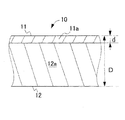
- the thickness of the hardened layer having a high average hardness and comprising such an induction-hardened structure is preferably 5 to 10 percent of the thickness of the leaf spring material.
- the distribution of the above-described compressive residual stress can be adjusted by adjusting the tensile stress, induction hardening conditions (output, movement speed, and the like), and cooling conditions (cooling power, movement speed, and the like) (hereinafter referred to as "quenching conditions").
- quenching conditions cooling conditions
- the distribution of the compressive residual stress achieved by induction hardening exhibits a substantially stable compressive stress value from the first surface toward the second surface side, which then suddenly decreases to a stress value near zero. That is, the residual compressive stress characteristically exhibits a step-type residual stress distribution.
- the location in which the compressive residual stress suddenly decreases from a predetermined value or higher extends to the region having the parent material structure of a deep portion more than the hardened layer having the induction-hardened structure. That is, the present invention makes it possible to improve the mechanical characteristics in the vicinity of the boundary face between the parent material structure and the induction-hardened structure, significantly improving the fatigue characteristics of the "spring.”
- the predetermined value of such compressive residual stress is preferably 650MPa or higher so as to significantly improve the spring service life.
- the leaf spring material of the present invention achieved based on the manufacturing method of the present invention, the leaf spring material reliably has a service life equivalent to three times that of leaf spring material comprising a conventional modified-ausformed material or higher when evaluated at a B 10 life, which is the fatigue life based on Weibull statistics and probability, for example.
- FIG. 1 and FIG. 2 An embodiment according to the present invention will now be described in detail, with reference to FIG. 1 and FIG. 2 .
- JIS SUP11A steel the steel is not limited thereto. Particularly, similar implementation is possible using a general spring steel (JIS4801) or its equivalent.
- a steel plate comprising a spring steel of a ferrite and pearlite dual phase structure is cut into a strip shape of predetermined dimensions.
- This strip-shaped steel is then shaped while heated and then subjected to quenching and tempering, resulting in a bent-shaped leaf spring material 10-1 prior to the stress-induced hardening treatment.
- This process is publicly known and will therefore not be described.
- Such a pre-treated leaf spring material 10-1 has a tempered martensite structure.
- Materials such as an as-is leaf spring material of the ferrite + pearlite dual phase structure not subjected to quenching, or a leaf spring material having a bainite structure achieved by isothermal transformation may also be suitably used.
- the pre-treated leaf spring material 10-1 is arranged on a fixed base 1 so that both upward warped end portions are on the top and the center portion is on the bottom.
- the pre-treated leaf spring material 10-1 is pressed down onto the fixed base 1 and fixed as a substantially flat plate using a clamp 2. At this time, due to the thickness of the pre-treated leaf spring material 10-1, a tensile stress TMPa is generated on a first surface (upper surface) 11, and a compressive stress is generated on a second surface (lower surface) 12.
- the first surface 11 is then heated at a predetermined output while moving high frequency heating means 3 along a longitudinal direction A of the pre-treated leaf spring material 10-1.
- the tensile stress of the first surface 11 is alleviated.
- the vicinity of the first surface 11 changes from a tempered martensite structure (or a ferrite + pearlite dual phase structure, a bainite structure, or the like) to a substantially single phase structure of high-temperature phase austenite.
- the heated section of the first surface 11 is sequentially cooled while moving cooling means 4 in the direction A following the high frequency heating means 3.
- the vicinity of the first surface 11 which changed to an austenite phase in the above-described heating processing is quenched to a martensite + austenite dual phase structure.
- the temperature distribution, quenching structure, and the like in the vicinity of the first surface of the pre-treated leaf spring material 10-1 can be adjusted by quenching conditions. That is, the thickness of an above-described quenched hardened surface 11a, and the residual stress distribution in the vicinity of the first surface 11 are adjustable.
- the above-described high frequency heating and quenching are performed on a predetermined section, such as the center section only or from one end portion to the other end portion, of the pre-treated leaf spring material 10-1, as suitably required so as to achieve the leaf spring material 10.
- the clamp 2 is then released, thereby releasing the compressive stress of the second surface so that the leaf spring material 10 returns once again to a shape wherein both end portions are warped upward. At this time, compressive stress is generated in the vicinity of the first surface 11.
- the leaf spring material 10 (given a thickness D) according to the embodiment comprises two layers: a parent material layer 12a having a parent material structure comprising a tempered martensite structure, and the hardened layer 11a of a thickness d having a martensite + retained austenite dual phase structure (quenched structure).
- the parent material structure may be a martensite, tempered martensite structure, bainite, or ferrite + pearlite dual phase structure, and processing that causes the carbide to be evenly distributed is preferably performed.
- FIG. 3 shows the results when leaf spring materials 10 with different Vickers hardness values of the hardened surface 11a were prepared and subjected to a fatigue test.
- the stress load conditions of the fatigue test were 700+/-560MPa.
- the test specimen having a Vickers hardness of 725HV a high number of cycles to failure of 9 x 10 4 or higher was achieved in each of the three tests (refer to reference code 31).
- the test specimen having a Vickers hardness of 630HV a number of cycles to failure of 9 x10 4 or less resulted in each of the three tests (refer to reference code 32).
- the steel plate is a steel plate having carbon content that is subjected to the above-described high frequency heat treatment and tempering, preferably achieving a Vickers hardness of 650HV.
- spring steel that includes SUP11A steel plate that generally achieves a Vickers hardness of approximately 650HV is insufficiently quenched if the Vickers hardness after high frequency heat treatment and tempering is 650HV or less, resulting in decarburization.
- the spring steel does not reliably achieve a service life equivalent to three times of a conventional leaf spring material comprising a typical improved-ausformed material at the B 10 life or higher, and is therefore not preferred.
- the hardness is not limited in terms of an upper limit.
- the upper limit of the hardness for the "spring material” is suitably determined according to the provided environment and the like.
- FIG. 4 shows the results when the leaf spring materials 10 having different thicknesses d of the hardened layer 11 a comprising a Vickers hardness of 650HV as described above are prepared and subjected to a fatigue test.
- the thickness d of the hardened layer 11a is 5% or lower or 10% or higher with respect to the steel plate thickness D
- the highest number of cycles to failure achieved is only 10 5 (refer to reference code 41).
- the thickness d of the hardened layer 11a is from 5 to 10% with respect to the steel plate thickness D
- a number of cycles to failure of at least 8 x 10 4 or higher can be achieved (refer to reference code 42). That is, the value of d / D x 100% is preferably within a certain range, and the range of this preferred value is from 5 to 10%.
- the vicinity of the hardened layer 11a of the parent material layer 12a is affected by heat during induction hardening, sometimes resulting in a hardness lower than that in the vicinity of the second surface 12 of the parent material layer 12a.
- the thickness d of the hardened layer 11a is small, the heat-affected layer yields when the bending stress of the "leaf spring" is loaded, sometimes resulting in a decrease in fatigue characteristics.
- the thickness d of the hardened layer 11a is too large, the compressive residual stress is not effectively achieved in the vicinity of the hardened layer 11 a by the restoring force of the parent material layer 12a.
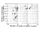
- FIG. 5 shows the result when leaf spring materials 10 with different surface compressive residual stresses of the first surface 11 are prepared and subjected to a fatigue test.
- the number of cycles to failure improves as the surface compressive residual stress increases.
- the surface compressive residual stress is preferably 650MPa or higher.
- the maximum value is equivalent to the yield stress.
- the hardened layer 11a achieved by induction hardening has a substantially constant hardness in the depth direction from the first surface 11, with the hardness suddenly decreasing at a certain depth position.
- a hardness distribution 61 of the leaf spring material 10 of the present invention the region from the first surface 11 to the position where the hardness suddenly decreases (that is, to the position where Vickers hardness is 650HV or less) is defined as the thickness d of the hardened layer 11 a.
- a hardness distribution 62 of a comparison example described later there is a substantially constant hardness in the depth direction and then the hardness suddenly decreases at a certain depth position.
- the thickness d of the hardened layer is defined as the region from the first surface 11 to the position where the hardness suddenly decreases. Furthermore, in the comparison example, as with the leaf spring material 10 of the present invention, in a case where Vickers hardness does not reach 650HV or higher, the thickness d of the hardened layer is defined as the region to the position of a depth where the hardness decreases to 20% that of the maximum value.
- the compressive residual stress distribution in the vicinity of the first surface 11 achieved by induction hardening has a substantially constant stress value in the depth direction from the first surface 11, and the absolute value of the stress value suddenly decreases at a certain depth position.
- a compressive residual stress distribution 71 of the leaf spring material 10 of the present invention the region from the first surface 11 to the position where the stress value suddenly decreases (that is, to the position where the stress value reaches the absolute value of the compressive stress value of substantially 650MPa or less) is defined as the thickness y of the compressive residual stress layer.
- the thickness y is similarly defined as the region from the first surface 11 to the position where the compressive residual stress suddenly decreases.
- FIG. 8 shows the result when leaf spring materials 10 wherein the thickness d of the hardened layer and the thickness y of the compressive residual stress layer are changed are prepared, and a fatigue test is conducted.
- the compressive residual stress value used for stipulating the thickness y is 650MPa. (Refer to the description of FIG. 5 described later indicating that the high fatigue strength is not achieved with a compressive residual stress value of 650MPa or less.)
- test sample (reference code 81) of a number of cycles to failure of one million or higher or a test sample (reference code 82) that ends in internal fracture at a number of cycles to failure of one million exists within the range where the thickness y of the compressive residual stress layer is larger than the thickness d of the hardened layer.
- test sample (reference code 83) in which a surface fracture occurred exists within the range where the thickness y of the compressive residual stress layer is smaller than the thickness d of the hardened layer.
- the yield of these sections can be prevented by imparting a compressive residual stress that surpasses the boundary surface of the hardened layer 11a / parent material layer 12a where the hardness suddenly changes, and the above-described heat-affected layer in the vicinity of the hardened layer 11a of the parent material layer 12a.
- the thickness y of the compressive residual stress layer is preferably greater than the thickness d of the hardened layer. That is, y / d > 1.0 is preferred.
- FIG. 9 shows the result when the leaf spring materials 10 comprising varied y/d ratios are further prepared and a fatigue test is conducted. From this figure, a trend showing a larger number of cycles to failure when y / d > 1.0 is revealed.
- the induction hardening conditions were changed to the substantially strip-shaped pre-treated leaf spring material 10-1 of an 18mm plate thickness comprising SUP11A steel plate and, as shown in Table 1, the samples of embodiments 1 to 3 and comparison examples 1 to 3 were prepared.
- embodiments 1 to 3 which satisfy y / d > 1.0, a 650HV or higher Vickers hardness of the hardened layer 11a, a compressive residual stress value of 650MPa or higher, and a 5 to 10% hardened layer thickness to steel plate thickness ratio have a reliable service life equivalent to three times that of a target conventional leaf spring material comprising a typical modified-ausformed material at a B 10 life.
- heat treatment may be performed in the drying process of the coating process.
- the drying temperature of the coating process is less than 80°C, cracks in the leaf spring material sometimes occur.
- the drying temperature is higher than 160°C, the residual stress is alleviated and, as described above, desired fatigue characteristics are not achieved.
- a heat treatment period of 5 minutes or less results in coating that has not dried, and a heat treatment period of 120 minutes or longer alleviates residual stress, causing an excessive energy loss in the drying process.
- conditions for tempering and conditions for drying should be taken into consideration to determine optimum conditions.
- a publicly known surface treatment process may also be added.
- the compressive residual stress on the topmost surface of the spring material is further increased by peening using fine grains, thereby further improving fatigue characteristics.
Landscapes
- Chemical & Material Sciences (AREA)
- Engineering & Computer Science (AREA)
- Mechanical Engineering (AREA)
- Physics & Mathematics (AREA)
- Thermal Sciences (AREA)
- Crystallography & Structural Chemistry (AREA)
- Materials Engineering (AREA)
- Metallurgy (AREA)
- Organic Chemistry (AREA)
- General Engineering & Computer Science (AREA)
- Heat Treatment Of Articles (AREA)
- Springs (AREA)
Applications Claiming Priority (1)
| Application Number | Priority Date | Filing Date | Title |
|---|---|---|---|
| JP2007307653A JP2009133335A (ja) | 2007-11-28 | 2007-11-28 | 板ばね材及びその製造方法 |
Publications (1)
| Publication Number | Publication Date |
|---|---|
| EP2078880A2 true EP2078880A2 (de) | 2009-07-15 |
Family
ID=40668707
Family Applications (1)
| Application Number | Title | Priority Date | Filing Date |
|---|---|---|---|
| EP08170509A Withdrawn EP2078880A2 (de) | 2007-11-28 | 2008-12-02 | Blattfedermaterial und Herstellungsverfahren dafür |
Country Status (4)
| Country | Link |
|---|---|
| US (1) | US20090133785A1 (de) |
| EP (1) | EP2078880A2 (de) |
| JP (1) | JP2009133335A (de) |
| DE (1) | DE102008044191A1 (de) |
Families Citing this family (9)
| Publication number | Priority date | Publication date | Assignee | Title |
|---|---|---|---|---|
| EP2502709B1 (de) | 2011-03-22 | 2017-02-01 | Black & Decker Inc. | Meissel |
| US9011161B2 (en) | 2012-02-10 | 2015-04-21 | Apple Inc. | Retention mechanism device having a lubricating member |
| US8882529B2 (en) * | 2012-08-24 | 2014-11-11 | Apple Inc. | Latch assembly having spring arms each with a retaining portion and a reinforced portion |
| US9333564B2 (en) | 2013-03-15 | 2016-05-10 | Black & Decker Inc. | Drill bit |
| USD734792S1 (en) | 2013-03-15 | 2015-07-21 | Black & Decker Inc. | Drill bit |
| USD737875S1 (en) | 2013-03-15 | 2015-09-01 | Black & Decker Inc. | Drill bit |
| JP6076207B2 (ja) * | 2013-06-13 | 2017-02-08 | 中央発條株式会社 | 板ばねの製造方法 |
| US9573432B2 (en) * | 2013-10-01 | 2017-02-21 | Hendrickson Usa, L.L.C. | Leaf spring and method of manufacture thereof having sections with different levels of through hardness |
| LU505772B1 (de) * | 2023-12-13 | 2025-06-19 | Phoenix Contact Gmbh & Co | Feder, Verfahren zur Herstellung einer Feder, Baugruppe umfassend eine Feder, Verfahren zur Herstellung einer Baugruppe und Federkraftklemme |
Citations (2)
| Publication number | Priority date | Publication date | Assignee | Title |
|---|---|---|---|---|
| JP2004323912A (ja) | 2003-04-24 | 2004-11-18 | Chuo Spring Co Ltd | 高強度コイルばね及びその製造方法 |
| JP2006071082A (ja) | 2004-09-06 | 2006-03-16 | Horikiri:Kk | 板ばね及びその製造方法 |
-
2007
- 2007-11-28 JP JP2007307653A patent/JP2009133335A/ja active Pending
-
2008
- 2008-11-26 US US12/324,586 patent/US20090133785A1/en not_active Abandoned
- 2008-11-28 DE DE102008044191A patent/DE102008044191A1/de not_active Withdrawn
- 2008-12-02 EP EP08170509A patent/EP2078880A2/de not_active Withdrawn
Patent Citations (2)
| Publication number | Priority date | Publication date | Assignee | Title |
|---|---|---|---|---|
| JP2004323912A (ja) | 2003-04-24 | 2004-11-18 | Chuo Spring Co Ltd | 高強度コイルばね及びその製造方法 |
| JP2006071082A (ja) | 2004-09-06 | 2006-03-16 | Horikiri:Kk | 板ばね及びその製造方法 |
Also Published As
| Publication number | Publication date |
|---|---|
| DE102008044191A1 (de) | 2010-06-02 |
| JP2009133335A (ja) | 2009-06-18 |
| US20090133785A1 (en) | 2009-05-28 |
Similar Documents
| Publication | Publication Date | Title |
|---|---|---|
| EP2078880A2 (de) | Blattfedermaterial und Herstellungsverfahren dafür | |
| EP0092815A2 (de) | Fahrzeugstabilisator und Verfahren zu dessen Herstellung | |
| CN101983247B (zh) | 钢材、钢材的制造方法及钢材的制造装置 | |
| EP2896712A1 (de) | Schraubendruckfeder und verfahren zur herstellung davon | |
| EP2623627A1 (de) | Einsatzstahl und herstellungsverfahren dafür | |
| CN102803522A (zh) | 谐波齿轮用基材的制造方法 | |
| WO2000075381A1 (en) | High-strength spring and production method therefor | |
| US20130008566A1 (en) | Spring and method for producing same | |
| US20110232810A1 (en) | Method for heat treatment of coiled spring | |
| CN103993154A (zh) | 合金钢齿轮的热处理方法 | |
| JP5946238B2 (ja) | ベアリングレースの製造方法 | |
| CN104099518B (zh) | 渗碳部件、其制造方法、和渗碳部件用钢 | |
| JPH11114827A (ja) | コイルばねの製法 | |
| EP3187600B1 (de) | Edelstahlfederherstellungsverfahren | |
| EP2065612A1 (de) | Blattfedermaterial und entsprechendes Herstellungsverfahren | |
| EP2548976A1 (de) | Federstahl und oberflächenbehandlungsverfahren für ein stahlmaterial | |
| JP4488347B2 (ja) | 板ばね及びその製造方法 | |
| JP5582855B2 (ja) | 機械構造部品の製造方法 | |
| CN115386694A (zh) | 高碳轴承钢心部强韧化和表面超硬化的复合热处理方法 | |
| JP2008106856A (ja) | ベルト式無段変速機用シーブ部材及びその製造方法 | |
| EP2811039B1 (de) | Verfahren zur herstellung eines schmiedestückes | |
| JP4970811B2 (ja) | 高面圧用部品とその製造方法 | |
| WO2015090958A1 (en) | Process for treating steel components | |
| JP2004323912A (ja) | 高強度コイルばね及びその製造方法 | |
| CN114317928B (zh) | 一种18CrNiMo7-6风电齿轮钢材料热处理方法 |
Legal Events
| Date | Code | Title | Description |
|---|---|---|---|
| PUAI | Public reference made under article 153(3) epc to a published international application that has entered the european phase |
Free format text: ORIGINAL CODE: 0009012 |
|
| AK | Designated contracting states |
Kind code of ref document: A2 Designated state(s): AT BE BG CH CY CZ DE DK EE ES FI FR GB GR HR HU IE IS IT LI LT LU LV MC MT NL NO PL PT RO SE SI SK TR |
|
| AX | Request for extension of the european patent |
Extension state: AL BA MK RS |
|
| STAA | Information on the status of an ep patent application or granted ep patent |
Free format text: STATUS: THE APPLICATION HAS BEEN WITHDRAWN |
|
| 18W | Application withdrawn |
Effective date: 20101007 |