EP2078968A2 - Cinémomètre laser à ouverture synthétique avec forme d'onde à mode synchronisé grésillée - Google Patents
Cinémomètre laser à ouverture synthétique avec forme d'onde à mode synchronisé grésillée Download PDFInfo
- Publication number
- EP2078968A2 EP2078968A2 EP09005227A EP09005227A EP2078968A2 EP 2078968 A2 EP2078968 A2 EP 2078968A2 EP 09005227 A EP09005227 A EP 09005227A EP 09005227 A EP09005227 A EP 09005227A EP 2078968 A2 EP2078968 A2 EP 2078968A2
- Authority
- EP
- European Patent Office
- Prior art keywords
- laser
- ladar system
- range
- phase
- chirped
- Prior art date
- Legal status (The legal status is an assumption and is not a legal conclusion. Google has not performed a legal analysis and makes no representation as to the accuracy of the status listed.)
- Granted
Links
- 230000003287 optical effect Effects 0.000 claims abstract description 32
- 239000013078 crystal Substances 0.000 claims abstract description 11
- 238000013519 translation Methods 0.000 claims abstract description 10
- 238000013459 approach Methods 0.000 abstract description 10
- 230000007246 mechanism Effects 0.000 abstract description 4
- 238000003384 imaging method Methods 0.000 description 8
- 238000012937 correction Methods 0.000 description 6
- 238000005314 correlation function Methods 0.000 description 6
- 238000010586 diagram Methods 0.000 description 6
- 238000000034 method Methods 0.000 description 6
- 230000001427 coherent effect Effects 0.000 description 5
- 230000008859 change Effects 0.000 description 4
- 238000013507 mapping Methods 0.000 description 4
- 230000007123 defense Effects 0.000 description 3
- 238000012986 modification Methods 0.000 description 3
- 230000004048 modification Effects 0.000 description 3
- 230000004044 response Effects 0.000 description 3
- 238000001228 spectrum Methods 0.000 description 3
- 230000003190 augmentative effect Effects 0.000 description 2
- 230000005540 biological transmission Effects 0.000 description 2
- 230000006835 compression Effects 0.000 description 2
- 238000007906 compression Methods 0.000 description 2
- 238000001514 detection method Methods 0.000 description 2
- 239000000284 extract Substances 0.000 description 2
- 238000005259 measurement Methods 0.000 description 2
- 238000005070 sampling Methods 0.000 description 2
- 238000012876 topography Methods 0.000 description 2
- 230000035559 beat frequency Effects 0.000 description 1
- 230000003111 delayed effect Effects 0.000 description 1
- 238000013461 design Methods 0.000 description 1
- 238000011161 development Methods 0.000 description 1
- 239000011521 glass Substances 0.000 description 1
- 239000000463 material Substances 0.000 description 1
- 239000000203 mixture Substances 0.000 description 1
- 238000002360 preparation method Methods 0.000 description 1
- 230000008569 process Effects 0.000 description 1
- 230000003595 spectral effect Effects 0.000 description 1
- 230000007480 spreading Effects 0.000 description 1
- 239000000126 substance Substances 0.000 description 1
Images


Classifications
-
- G—PHYSICS
- G01—MEASURING; TESTING
- G01S—RADIO DIRECTION-FINDING; RADIO NAVIGATION; DETERMINING DISTANCE OR VELOCITY BY USE OF RADIO WAVES; LOCATING OR PRESENCE-DETECTING BY USE OF THE REFLECTION OR RERADIATION OF RADIO WAVES; ANALOGOUS ARRANGEMENTS USING OTHER WAVES
- G01S17/00—Systems using the reflection or reradiation of electromagnetic waves other than radio waves, e.g. lidar systems
- G01S17/003—Bistatic lidar systems; Multistatic lidar systems
-
- G—PHYSICS
- G01—MEASURING; TESTING
- G01S—RADIO DIRECTION-FINDING; RADIO NAVIGATION; DETERMINING DISTANCE OR VELOCITY BY USE OF RADIO WAVES; LOCATING OR PRESENCE-DETECTING BY USE OF THE REFLECTION OR RERADIATION OF RADIO WAVES; ANALOGOUS ARRANGEMENTS USING OTHER WAVES
- G01S17/00—Systems using the reflection or reradiation of electromagnetic waves other than radio waves, e.g. lidar systems
- G01S17/02—Systems using the reflection of electromagnetic waves other than radio waves
- G01S17/06—Systems determining position data of a target
- G01S17/08—Systems determining position data of a target for measuring distance only
- G01S17/10—Systems determining position data of a target for measuring distance only using transmission of interrupted, pulse-modulated waves
- G01S17/26—Systems determining position data of a target for measuring distance only using transmission of interrupted, pulse-modulated waves wherein the transmitted pulses use a frequency-modulated or phase-modulated carrier wave, e.g. for pulse compression of received signals
-
- G—PHYSICS
- G01—MEASURING; TESTING
- G01S—RADIO DIRECTION-FINDING; RADIO NAVIGATION; DETERMINING DISTANCE OR VELOCITY BY USE OF RADIO WAVES; LOCATING OR PRESENCE-DETECTING BY USE OF THE REFLECTION OR RERADIATION OF RADIO WAVES; ANALOGOUS ARRANGEMENTS USING OTHER WAVES
- G01S17/00—Systems using the reflection or reradiation of electromagnetic waves other than radio waves, e.g. lidar systems
- G01S17/88—Lidar systems specially adapted for specific applications
- G01S17/89—Lidar systems specially adapted for specific applications for mapping or imaging
- G01S17/90—Lidar systems specially adapted for specific applications for mapping or imaging using synthetic aperture techniques
-
- G—PHYSICS
- G01—MEASURING; TESTING
- G01S—RADIO DIRECTION-FINDING; RADIO NAVIGATION; DETERMINING DISTANCE OR VELOCITY BY USE OF RADIO WAVES; LOCATING OR PRESENCE-DETECTING BY USE OF THE REFLECTION OR RERADIATION OF RADIO WAVES; ANALOGOUS ARRANGEMENTS USING OTHER WAVES
- G01S7/00—Details of systems according to groups G01S13/00, G01S15/00, G01S17/00
- G01S7/48—Details of systems according to groups G01S13/00, G01S15/00, G01S17/00 of systems according to group G01S17/00
- G01S7/483—Details of pulse systems
- G01S7/484—Transmitters
-
- H—ELECTRICITY
- H01—ELECTRIC ELEMENTS
- H01S—DEVICES USING THE PROCESS OF LIGHT AMPLIFICATION BY STIMULATED EMISSION OF RADIATION [LASER] TO AMPLIFY OR GENERATE LIGHT; DEVICES USING STIMULATED EMISSION OF ELECTROMAGNETIC RADIATION IN WAVE RANGES OTHER THAN OPTICAL
- H01S3/00—Lasers, i.e. devices using stimulated emission of electromagnetic radiation in the infrared, visible or ultraviolet wave range
- H01S3/10—Controlling the intensity, frequency, phase, polarisation or direction of the emitted radiation, e.g. switching, gating, modulating or demodulating
- H01S3/105—Controlling the intensity, frequency, phase, polarisation or direction of the emitted radiation, e.g. switching, gating, modulating or demodulating by controlling the mutual position or the reflecting properties of the reflectors of the cavity, e.g. by controlling the cavity length
-
- H—ELECTRICITY
- H01—ELECTRIC ELEMENTS
- H01S—DEVICES USING THE PROCESS OF LIGHT AMPLIFICATION BY STIMULATED EMISSION OF RADIATION [LASER] TO AMPLIFY OR GENERATE LIGHT; DEVICES USING STIMULATED EMISSION OF ELECTROMAGNETIC RADIATION IN WAVE RANGES OTHER THAN OPTICAL
- H01S3/00—Lasers, i.e. devices using stimulated emission of electromagnetic radiation in the infrared, visible or ultraviolet wave range
- H01S3/10—Controlling the intensity, frequency, phase, polarisation or direction of the emitted radiation, e.g. switching, gating, modulating or demodulating
- H01S3/11—Mode locking; Q-switching; Other giant-pulse techniques, e.g. cavity dumping
- H01S3/1106—Mode locking
- H01S3/1109—Active mode locking
-
- H—ELECTRICITY
- H01—ELECTRIC ELEMENTS
- H01S—DEVICES USING THE PROCESS OF LIGHT AMPLIFICATION BY STIMULATED EMISSION OF RADIATION [LASER] TO AMPLIFY OR GENERATE LIGHT; DEVICES USING STIMULATED EMISSION OF ELECTROMAGNETIC RADIATION IN WAVE RANGES OTHER THAN OPTICAL
- H01S3/00—Lasers, i.e. devices using stimulated emission of electromagnetic radiation in the infrared, visible or ultraviolet wave range
- H01S3/10—Controlling the intensity, frequency, phase, polarisation or direction of the emitted radiation, e.g. switching, gating, modulating or demodulating
- H01S3/11—Mode locking; Q-switching; Other giant-pulse techniques, e.g. cavity dumping
- H01S3/1106—Mode locking
- H01S3/1112—Passive mode locking
-
- H—ELECTRICITY
- H01—ELECTRIC ELEMENTS
- H01S—DEVICES USING THE PROCESS OF LIGHT AMPLIFICATION BY STIMULATED EMISSION OF RADIATION [LASER] TO AMPLIFY OR GENERATE LIGHT; DEVICES USING STIMULATED EMISSION OF ELECTROMAGNETIC RADIATION IN WAVE RANGES OTHER THAN OPTICAL
- H01S3/00—Lasers, i.e. devices using stimulated emission of electromagnetic radiation in the infrared, visible or ultraviolet wave range
- H01S3/10—Controlling the intensity, frequency, phase, polarisation or direction of the emitted radiation, e.g. switching, gating, modulating or demodulating
- H01S3/106—Controlling the intensity, frequency, phase, polarisation or direction of the emitted radiation, e.g. switching, gating, modulating or demodulating by controlling devices placed within the cavity
- H01S3/107—Controlling the intensity, frequency, phase, polarisation or direction of the emitted radiation, e.g. switching, gating, modulating or demodulating by controlling devices placed within the cavity using electro-optic devices, e.g. exhibiting Pockels or Kerr effect
Definitions
- This invention relates to laser radar systems (ladars). Specifically, the present invention relates to synthetic aperture ladar systems.
- High resolution imaging at long ranges is becoming a commercial priority as well.
- High resolution imaging will allow high flying aircrafts to determine the content of open bay trucks, or whether people are carrying weapons or tools.
- Other applications such as NASA's desire to map possible landing sites for unmanned crafts, drive resolution requirements to just a couple of inches at ranges greater than 100 km.
- High resolution long range imaging would also be useful for numerous additional applications including Homeland Security and terrain surveillance.
- Infrared approaches have been used in the past for this application as well as synthetic aperture radar (SAR). Infrared approaches are limited by the physical aperture size of the optics.
- the laser transmitter In order to obtain the required down-range resolution, the laser transmitter must, in some cases, be modulated at bandwidths greater than a few gigahertz (GHz) in a non-ambiguous waveform.
- the present invention uses an intra-cavity modulation approach that divides the task into two sub-tasks: 1) chirping the laser and 2) simultaneously mode locking.
- the inventive system includes a source of a beam of electro-magnetic energy; a mechanism for mode locking the beam; and an arrangement for chirping the beam.
- the source is a laser.
- the mode locking mechanism may be an active element or a passive element.
- the beam is chirped with a translation mirror.
- the translation mirror may be driven with a piezo-electric drive coupled.
- the carrier is chirped with an electro-optical crystal disposed in the cavity of the laser.
- the laser is chirped to the free-spectral range limit, which is typically a few hundred megahertz (MHz), by scanning the optical length of the laser resonator.
- a fter simultaneously mode locking, the waveform created is a train of mode locked pulses that have an optical carrier frequency chirped in time. Adding the chirped component mitigates the occasional problem of range ambiguities when absolute range mapping is desired.
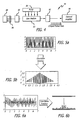
- Fig. 1 is a diagram showing an aircraft 10 employing a ladar system 12 constructed in accordance with the teachings of the present invention and illustrating general ladar principles of operation.
- the aircraft 10 has a velocity vector ( V ) 14 as it flies by a terrain 16.
- the ladar system 12 is mounted on the front of the aircraft 10 and transmits a laser beam 18 toward terrain 16 or another target (not shown).
- the transmitted laser beam 18 is a high-energy eye-safe Q-switched pulsed laser beam comprising a sequence of high-energy pulses.
- the Q-switched pulsed laser beam 18 reflects from the terrain 16, producing three laser returns 20 from three different surfaces of the terrain 16 for each pulse of the laser beam 18. By measuring the time between transmission of a given pulse and the detection of the corresponding laser returns by the ladar system 12, the distance to the terrain 16 and its various surfaces is determined.
- the aircraft 10 As the aircraft 10 passes over or by the terrain 16, it fires the laser 18 for a predetermined time, called the dwell time or the measuring time ( T meas ). Throughout the measuring time T , the angle ( ⁇ ) at which the transmitted laser beam 18 and the returns 20 strike and reflect from the terrain 16 changes ( ⁇ ). As the angle ⁇ changes, each surface of the terrain 16 yields a return at a slightly different frequency than returns from the other surfaces due to Doppler frequency shifts in the returns from the radial motion of the aircraft 10 relative to the terrain 16. The Doppler frequency shifts depend on the angle at which the transmitted laser beam 18 strikes the different surfaces of the terrain 16.
- Each return pulse 20 effectively samples the Doppler tones that are present due to the radial motion of the aircraft 10 relative to the terrain 16.
- Each return pulse is sampled several times ( N times), with each sample being stored in a range bin corresponding to the time at which the sample was taken. The time at which the sample was taken represents the distance or range corresponding to the sample.
- T meas Over the measuring time T meas , several return pulses are sampled by a high-speed A/D converter, as discussed more fully below. After all the samples have been taken, the phase and frequency correction process may be performed.
- the sampled data in N range bins and M pulses is output to Discrete Fourier Transform (DFT) modules.
- the DFT modules extract data from the individual range bins to compute frequency spectrum associated with each range bin.
- the frequency spectrum represents cross-range information, which indicates the relative angular position associated with the sampled data from each range bin. Consequently, the angular position associated with each range bin yields range and cross-range information for each surface of the terrain 16. This range and cross-range information may then be plotted to yield an accurate profile of the terrain 16 in the direction of travel 14 of the aircraft 12.
- the measuring time ( T meas ) multiplied by the velocity ( V ) of the aircraft is proportional to the synthetic aperture, which is inversely proportional to the cross-range resolution of the ladar system 12.
- T meas is the measuring time or dwell window during which scene measurements are performed by the ladar system 12.
- T meas represents the time during which the transmitted laser must remain coherent.
- the ladar system 12 of the present invention does not require that the transmitted laser beam 18 be coherent.
- the measuring time T meas is approximately 1.875 milliseconds.
- the bandwidth required for the line of sight resolution is approximately 300 MHz.
- the figure of merit, the bandwidth-time product, BT, of laser beam 18 is approximately 560,000.
- Fig. 2 is a graph 30 showing an exemplary Q-switched laser pulse train 18 transmitted by the ladar system 12 of Fig. 1 and a received pulse train 20 detected by the ladar system 12 after reflection off three different surfaces of the terrain 16 of Fig. 1 .
- the graph 30 is shows pulse intensity versus time.
- Each pulse ( n ⁇ n + 3) of the transmitted pulse train 18 yields, a short time later, a corresponding set of three returns in the received pulse train 20, one return for each surface reflected by the terrain 16 of Fig. 1 .
- the return pulse train 20 has three distinct returns for each transmitted pulse of the pulse train 18.
- each set of three returns in the pulse train 20 are typically closer together and may blend into a single return pulse, with different peaks, each peak corresponding to a surface of the terrain 16.
- the transmitted pulse train 18 is incoherent from pulse to pulse, and consequently has a random phase and random frequency offsets.
- Each pulse of the transmitted pulse train 32 is associated with a frequency offset ( f n ) and random phase ( ⁇ n ).
- the ladar system 12 of Fig. 1 measures the frequency offsets f n and phases ⁇ n of the outgoing noncoherent pulse train 18 to compensate the return pulse train 20 for frequency offset f n and phases ⁇ n , as discussed more fully below.
- Fig. 3(a) and Fig. 3(b) are more detailed diagrams of the ladar system 12 of Fig. 1 employing an In-phase (I) and Quadrature (Q) laser receiver 40, which is an optical heterodyne detector.
- I In-phase
- Q Quadrature
- various well-known components, such as power sources, signal amplifiers, noise filters, and focusing optics have been omitted from Fig. 3(a) and Fig. 3(b) , however those skilled in the art with access to the present teachings will know which components to implement and how to implement them to meet the needs of a given application.
- the ladar system 12 includes a common aperture 42, which communicates with a Q-switched laser transmitter 44 and the optical heterodyne receiver detector 40.
- the transmitter 44 and the heterodyne receiver 40 communicate with a synthetic aperture processor 46, which communicates with a computer 48, such as a display, target tracking, or fire control computer.
- the Q-switched transmitter 44 receives input from a signal generator 48, which receives input from a transmit controller 50.
- the ladar system 12 is a monostatic ladar system since the transmitter 44 and the receiver 40 share the common aperture 42.
- the Q-switched transmitter 44 includes a transmit laser that may be implemented as an Er:Yb:Glass Q-switched laser or an Er:Yb:YAG high-power laser.
- the ladar system 12 may be another type of ladar system, such as a bistatic ladar system employing a different type of transmit laser, without departing from the scope of the present invention.
- the transmit controller 50 provides control signals to the signal generator 48 which specify waveform details, such as pulse width, energy per pulse, pulse spacing, and so on.
- the signal generator 48 generates an electrical signal according to the waveform details.
- the electrical signal drives the Q-switched laser transmitter 44, which produces a Q-switched laser beam 18 characterized by the waveform details.
- the Q-switched laser transmitter 44 determines I and Q components of the Q-switched transmitted laser beam 18 before transmission from the ladar system 12.
- the I and Q components of the outgoing Q-switched laser beam 18 are determined similarly to the optical heterodyne receiver 40, as discussed more fully below.
- the I and Q components of the outgoing Q-switched laser beam 18 are input to a phase and frequency offset detector 68 of the synthetic aperture processor 46.
- the transmit controller 50 and/or the signal generator 48 may be implemented via software running on the synthetic aperture processor 46 without departing from the scope of the present invention.
- the transmitted laser beam 18 reflects from the scene, such as the terrain 16 of Fig. 1 , yielding the laser return signal 20, which is detected by the optical heterodyne receiver 40.
- the optical heterodyne receiver 40 includes a local oscillator laser 52, a first beam splitter arrangement 54, a second beam splitter arrangement 56, a quarter-wave retarder 58, an in-phase ( I ) optical detector 60, a quadrature (Q) optical detector 62, and a high speed (typically 1 GHz or greater) analog-to-digital converters 64.
- the local oscillator 52 transmits a coherent Continuous Wave (CW) reference laser beam, in the form of a sine wave, to the first beam splitter arrangement 54.
- the first beam splitter arrangement 54 transmits the local oscillator reference signal to the I -detector 60 and the quarter-wave retarder 58.
- the quarter-wave retarder 58 converts the input sine wave into a laser beam having a cosine waveform and transmits the cosine waveform to the surface of the Q-detector 62.
- the first beam splitter arrangement 56 splits the laser return beam 20 received from the common aperture 42 into two sinusoidal beams. The two sinusoidal beams strike the I -detector 60 and the Q -detector 62 coincident with the beams output by the first beam splitter arrangement 54 and the quarter-wave optical retarder 58, respectively.
- the I -detector 60 and the Q -detector 62 detect beat frequencies, called Doppler tones, corresponding to I and Q received signal components, respectively.
- the I- detector 60 and the Q -detector 62 convert respective the I and Q received signal components into corresponding analog I and Q electrical signals.
- the I and Q analog electrical signals are then sampled at 1GHz via Analog-to-Digital (A/D) converters 64.
- A/D converters output a 1 GHz digital received signal having I and Q components.
- the 1 GHz digital received signal is then input to a range demultiplexer 66 implemented in the synthetic aperture processor 46.
- the synthetic aperture processor 46 includes the range demultiplexer 66, which provides input to a full phase circuit 70.
- the full phase circuit 70 provides input to a phase corrector 72.
- the phase corrector 72 also receives input from the phase and frequency offset detector 6 8 from the M transmitted pulses.
- the phase corrector 72 provides output to a set of N range bins 74 and M pulses per range bin.
- Each n th range bin of the N range bins 74 provides output to N corresponding Discrete Fourier Transform (DFT) circuits 76.
- the N DFT modules 76 provide input to N corresponding centroid detectors 78.
- the N centroid detectors 78 provide Doppler information to the computer 48 and to N corresponding peak intensity detectors 80.
- the peak intensity detectors 80 provide intensity input to the computer 48.
- the various modules 66 - 80 of the synthetic aperture processor 46 are implemented in software.
- the synthetic aperture processor 46 may be implemented by the computer 48 without departing from the scope of the present invention.
- the A/D converters 64 sample the analog signals output from the I -detector 60 and the Q -detector 62 at predetermined intervals based on a priori knowledge of the pulse spacing of the transmitted laser beam 18.
- the A/D converters 64 may be preset with pulse spacing information or may obtain the pulse spacing information via a connection (not shown) to the Q-switched laser transmitter 44.
- the intervals at which the A/D converters 64 sample the received signal coincide with pulses the received analog I and Q signal output from the detectors 60 and 62.
- the A/D converters take N samples per pulse.
- the number of samples N taken per pulse depends on the pulse width of the transmitted laser 18 and the sampling rate (1 GHz) of the A/D converters 64 and the range window that is desired. In the illustrative embodiment, the sampling rate is approximately three nanoseconds.
- the exact pulse width, intensity, frequency, and other waveform characteristics of the transmitted laser beam 18 are application-specific and may be determined by one skilled in the art to meet the
- Each of the N digital I and Q samples output by the A/D converters 64 per pulse are demultiplexed onto a single path by the range demultiplexer 66 and input to the full phase circuit 70.
- the full phase circuit 70 expresses the sampled demultiplexed I and Q signal output from the range demultiplexer 66 in imaginary form, r I + i r Q , where r I is the in-phase component of the received signal and i r Q is the imaginary component. Expressing the return signal in this form ( r I + ir Q ) facilitates phase correction by the phase corrector 72.
- Frequency and phase information about the transmitted laser beam 18 is provided to the phase and frequency offset detector 68.
- I and Q components, t I and i t Q , respectively, of the transmitted laser beam 18 are forwarded to the phase and frequency offset detector 68 by the Q-switched laser transmitter 44.
- the Q-switched laser transmitter 44 determines the I and Q components of the transmitted laser beam 18 similar to the way the optical heterodyne receiver 40 determines I and Q components of the received signal 20.
- the phase and frequency offset detector 68 extracts frequency and phase information ([ ⁇ 1 , ⁇ 2 , ⁇ 3 ,..., ⁇ M ], [ f 1, f 2 , f 3 ,..., f M ]) from the transmit signal ( t I + it Q ) via methods known in the art.
- the phase and frequency information includes measured phase offsets and frequency offsets that occur from one Q-switched pulse to the next.
- the relative phase ⁇ n of each transmitted pulse of the transmitted beam 18 is detected and recorded by the transmitter 44 of the ladar system 12.
- a measured phase array [ ⁇ 1 , ⁇ 2 , ⁇ 3 ,..., ⁇ M ]
- a frequency offset (frequency hop) array [ f 1 , f 2 , f 3 ,..., f M ]
- the pulses of the received signal are not necessarily evenly spaced.
- the reference beam output by the local oscillator 52 is coherent throughout the measuring time T meas .
- the local oscillator 52 may be implemented with a standard laser usually of the same base material as the transmitter, such as Er:Yb:Glass or Er:YAG in the current embodiment.
- the coherence of the local oscillator 52 which is relatively low-power and runs in CW mode, is easier to maintain than a high energy pulsed transmit laser, such as the Q-switched laser transmitter 44.
- the range demultiplexer 66 performs range demultiplexing.
- the range demultiplexer 66 adjusts the input bit stream so that the subsequent phase correction is only performed at range bins associated with expected returns.
- the phase corrector 72 corrects it.
- the phase corrector 72 employs the phase and frequency information ([ ⁇ 1 , ⁇ 2 , ⁇ 3 ,..., ⁇ M ], [ f 1 , f 2 , f 3 ,..., f M ]) of all M pulses, to apply a phase correction term ( e (-i( ⁇ m +2 ⁇ f m ⁇ )) ) to the received signal r I + ir Q .
- the phase-corrected signal S n is then clocked into the range bins 74, which may be implemented via a software register.
- the range bins 74 are cleared in parallel as the contents of the range bins 74 are clocked into the N corresponding DFT modules 76.
- the DFT modules 76 compute the square of the magnitude of the DFT of the signal corresponding to each range bin.
- DFT 1 ( ⁇ ) represents the frequency response associated with the first range bin of the range bins 76.
- the magnitude squared of DFT n ( ⁇ ) will preferably have one or more peaks at the frequency corresponding to the Doppler tone associated with the n th range bin as discussed more fully below. This frequency peak represents cross-range information associated with the n th range bin.
- the DFT modules 76 compute the DFTI 1 ( ⁇ ) via Fast Fourier Transform (FFT) algorithms, which are well known in the art.
- the DFT modules 76 output frequency responses (spectrums) to the corresponding centroid detectors 78.
- the centroid detectors 78 compute the centroids of the frequency responses, via methods known in the art, yielding center frequencies.
- the center frequencies output by the centroid detectors 78 represent cross-range information in the form of Doppler frequencies.
- This cross-range information is input to the computer 48.
- the computer 48 may then generate a range versus cross-range plot based on the cross-range information and the range information.
- the range information is indicated by the number of the range bin associated with cross-range information output by each centroid detector 78.
- the cross-range information from the centroid detectors 78 is input to corresponding peak intensity detectors 80.
- the peak intensity detectors 80 compute intensity information corresponding to the magnitudes of the peaks of the centroids and not just the frequency locations of the centroids.
- the intensity information corresponding to each range bin is also input to the computer 48.
- the computer 48 may include a display, tracking software, fire control software, chemical analysis software, and so on.
- the computer 48 runs software for displaying a cross-range versus range plot, which is indicative of a profile of the scene, such as the terrain 16 of Fig. 1 being imaged.
- the line of sight resolution is obtained by using a high bandwidth signal, such as a short pulse or train of pulses, but the cross-range resolution is usually limited by the detector pixel field of view (FOV).
- FOV detector pixel field of view
- ⁇ the optical signal wavelength
- D r the receiver aperture.
- a solution to this limitation is to apply the same technique used in the radar world where the problem is more severe due to the much longer wavelength, and that is to use synthetic aperture reception.
- the measuring time T meas
- twice the aircraft velocity times the measuring time 2*V*T meas
- the bandwidth-time product of the waveform needs to be approximately 300,000.
- the natural waveform of the laser i.e. a mode locked waveform
- linear FM chirping is a frequency modulation scheme by which a carrier is modulated with plural frequencies sequentially indexed over a short time frame. For high resolution, the carrier must be chirped over a large frequency range.
- the present invention takes a mixed approach to utilize the advantages of the linear FM chirped and the mode locked waveforms.
- the laser is intra-cavity chirped up to the limit mode spacing or free spectral range, typically a few hundred MHz, while simultaneously mode locking to create a n unambiguous waveform that will have a bandwidth to multiple GHz.
- Fig. 4 shows a block diagram of a laser 44 that will output a train of chirped mode locked pulses using mirror position modulation in accordance with an illustrative embodiment of the teachings of the present invention.
- Portion of the transmitted beam is sampled and by the Phase and Frequency Offset Detector 68, which consists of the same hardware components as the Heterodyne Receiver in figure 3A .
- the stored reference of the waveform of the Frequency Offset Detector 68 is fed to the Phase Corrector that corrects the phase and frequency deviations by performing a multiplication of the reference with the detected signal.
- a pump source 84 provides energy to a gain medium 82, which constitutes the laser resonator.
- the gain medium is conventional as is the pump source 84.
- a passive or active mode locking element 86 is disposed in optical alignment with the gain medium 82. In the best mode, the mode locking element is conventional in design.
- the beam output by the gain medium 82 reflects off a translation laser scanning end mirror 90 driven by a piezo-electric drive 88.
- the piezo-electric drive 88 is controlled by the signal generator 49 and transmit controller 50 of fig. 3B .
- the piezo-electric drive is replaced with an electro-optical crystal inside the laser cavity. The crystal would be driven with a ramp to achieve a chirping of the carrier.
- a partially reflecting end mirror 92 serves to provide the laser output of 44(A).
- the combination of the mode locking element and the translation end mirror yields an output pulse train that is mode locked and chirped.
- chirping is achieved by scanning the resonator end mirror by one wavelength.
- the combined modulation of mode locking and linear FM chirping creates an unambiguous waveform using relatively proven methods of laser modulation that can be implemented in a compact transmitter. This signal is output to an optional amplifier 94.
- the receiver shown in Fig. 3(a) consists of two channels, the in-phase and quadrature, I and Q, to distinguish between positive and negative frequencies.
- the local oscillator, LO, laser reference is delayed by quarter if a wavelength, ⁇ /2.
- the analog signals are digitized and recombined in memory. Each range bin is separated by the range demultiplexer, where a single return at a range bin would appear as shown in figure 6a , a chirped signal.
- the chirped signal is then convolved with a reference version of itself yielding the compressed signal shown in figure 6b .
- This detection step of the chirped waveform is the standard used in synthetic aperture radar for matched filter range transform.
- Table 1 shows the list of some waveforms that may be considered for long range ladar imaging and some of the advantages and disadvantages of each.
- the simplest waveform to generate may be a single pulse (i.e. cavity-cavity dumped) with a pulse width short enough (i.e., bandwidth high enough) to obtain the range resolution desired.
- the waveform repetition rate samples the Doppler width due to the beam angular spread and must be set at twice the maximum frequency.
- the single pulse may not be possible due to potential damage considerations.
- the waveform may be stretched in time by either spreading the energy into various mode locked pulses or a single cw (continuous wave) linear (or quasi-linear) FM chirp.
- the single pulse or mode locked burst may be most suitable for crystal lasers using intracavity modulation and the high bandwidth FM chirp may be most suitable for either short-cavity low power lasers and/or external modulation approaches.
- optical frequency modulators with bandwidth of multi-GHz are rare to non-existent. Such devices exist in the telecom area in the wavelengths of 1.3 to 1.5 ⁇ m. However, to develop a modulator operable at other wavelengths, a significant development effort would be required.
- a natural laser waveform of mode lock is used.
- a passive or active mode locking modulation element is used running at the laser mode spacing frequency c/(2L), where 'c' is the speed of light and 'L' is the laser resonator optical length.
- Fig. 5(a) and Fig. 5(b) show a correlation function of a train of mode locked pulses.
- the correlation function is the matched filter of the waveform, which is implemented by correlating the waveform to itself.
- Fig. 5(a) shows the transmitted waveform
- Fig. 5(b) shows the result of the self correlation.
- High resolution is obtained by the fine comb of pulses, but one pulse is very similar to the next, creating a range ambiguity.
- the mode lock pulse bandwidth is only limited by the line width of the laser and this can be multiple gigahertz. By chirping just the mode spacing frequency of a few megahertz, one can break the ambiguous correlation and separate the individual pulse returns as shown in Fig. 6(a) and Fig. 6(b) .
- Fig. 6(a) and Fig. 6(b) show a correlation function of a train of mode locked pulses chirped in accordance with the teachings of the present invention.
- Fig. 6(a) shows the detected chirped waveform (as a result of a single return point) and Fig. 6(b) shows the result of the self correlation.
- the chirping breaks the range ambiguity allowing a receiver to select individual pulses and determine the centroid of the waveform.
- the chirping of the beam is achieved by scanning the position of one of the laser end mirrors 90 or 92 by a distance equaling the optical wavelength.
Landscapes
- Physics & Mathematics (AREA)
- Engineering & Computer Science (AREA)
- Electromagnetism (AREA)
- Computer Networks & Wireless Communication (AREA)
- General Physics & Mathematics (AREA)
- Radar, Positioning & Navigation (AREA)
- Remote Sensing (AREA)
- Plasma & Fusion (AREA)
- Optics & Photonics (AREA)
- Optical Radar Systems And Details Thereof (AREA)
- Lasers (AREA)
Applications Claiming Priority (2)
| Application Number | Priority Date | Filing Date | Title |
|---|---|---|---|
| US10/732,427 US7505488B2 (en) | 2001-09-28 | 2003-12-09 | Synthetic aperture ladar with chirped modelocked waveform |
| EP04257594A EP1542036A1 (fr) | 2003-12-09 | 2004-12-07 | LADAR à synthèse d'ouverture ayant une forme d'onde de type chip et à sélectivité de mode |
Related Parent Applications (2)
| Application Number | Title | Priority Date | Filing Date |
|---|---|---|---|
| EP04257594A Division EP1542036A1 (fr) | 2003-12-09 | 2004-12-07 | LADAR à synthèse d'ouverture ayant une forme d'onde de type chip et à sélectivité de mode |
| EP04257594.4 Division | 2004-12-07 |
Publications (3)
| Publication Number | Publication Date |
|---|---|
| EP2078968A2 true EP2078968A2 (fr) | 2009-07-15 |
| EP2078968A3 EP2078968A3 (fr) | 2011-11-23 |
| EP2078968B1 EP2078968B1 (fr) | 2013-02-13 |
Family
ID=34523047
Family Applications (2)
| Application Number | Title | Priority Date | Filing Date |
|---|---|---|---|
| EP09005227A Ceased EP2078968B1 (fr) | 2003-12-09 | 2004-12-07 | Cinémomètre laser à ouverture synthétique avec forme d'onde à mode synchronisé grésillée |
| EP04257594A Ceased EP1542036A1 (fr) | 2003-12-09 | 2004-12-07 | LADAR à synthèse d'ouverture ayant une forme d'onde de type chip et à sélectivité de mode |
Family Applications After (1)
| Application Number | Title | Priority Date | Filing Date |
|---|---|---|---|
| EP04257594A Ceased EP1542036A1 (fr) | 2003-12-09 | 2004-12-07 | LADAR à synthèse d'ouverture ayant une forme d'onde de type chip et à sélectivité de mode |
Country Status (2)
| Country | Link |
|---|---|
| US (1) | US7505488B2 (fr) |
| EP (2) | EP2078968B1 (fr) |
Families Citing this family (20)
| Publication number | Priority date | Publication date | Assignee | Title |
|---|---|---|---|---|
| US8190162B2 (en) * | 2003-09-15 | 2012-05-29 | Broadcom Corporation | Radar detection circuit for a WLAN transceiver |
| US20060139620A1 (en) * | 2004-12-27 | 2006-06-29 | Hopwood Francis W | Method and apparatus for coherently processing signals from incoherent sources including laser signals |
| CN1313836C (zh) * | 2005-02-05 | 2007-05-02 | 中国科学院上海光学精密机械研究所 | 电光调制脉冲激光测距仪 |
| CN101317310B (zh) * | 2005-12-06 | 2010-12-08 | 伊雷克托科学工业股份有限公司 | 同时模式锁定q开关激光系统 |
| NO332425B1 (no) * | 2006-03-21 | 2012-09-17 | Aanderaa Data Instr As | Fremgangsmåte og system for å måle relativ fart av vann. |
| US7978124B2 (en) * | 2009-08-03 | 2011-07-12 | Raytheon Company | Method and system for motion compensation for hand held MTI radar sensor |
| US8629975B1 (en) | 2010-08-18 | 2014-01-14 | The United States Of America As Represented By The Secretary Of The Air Force | Apparatus and method for a multiple aperture coherent ladar |
| US8947647B2 (en) | 2011-12-13 | 2015-02-03 | Raytheon Company | Range-resolved vibration using large time-bandwidth product LADAR waveforms |
| US8767187B2 (en) | 2011-12-13 | 2014-07-01 | Raytheon Company | Doppler compensation for a coherent LADAR |
| US8947644B2 (en) | 2012-01-19 | 2015-02-03 | Raytheon Company | Using multiple waveforms from a coherent LADAR for target acquisition |
| US9057605B2 (en) * | 2012-12-06 | 2015-06-16 | Raytheon Company | Bistatic synthetic aperture ladar system |
| CN103245939B (zh) * | 2013-05-22 | 2015-05-13 | 中国科学院上海光学精密机械研究所 | 直视合成孔径激光成像雷达发射光束直接波面变换扫描器 |
| CN104898107B (zh) * | 2015-06-17 | 2017-06-20 | 西安电子科技大学 | 一种多发多收合成孔径激光雷达信号处理方法 |
| US12123950B2 (en) | 2016-02-15 | 2024-10-22 | Red Creamery, LLC | Hybrid LADAR with co-planar scanning and imaging field-of-view |
| US12399278B1 (en) | 2016-02-15 | 2025-08-26 | Red Creamery Llc | Hybrid LIDAR with optically enhanced scanned laser |
| US12399279B1 (en) | 2016-02-15 | 2025-08-26 | Red Creamery Llc | Enhanced hybrid LIDAR with high-speed scanning |
| US11556000B1 (en) | 2019-08-22 | 2023-01-17 | Red Creamery Llc | Distally-actuated scanning mirror |
| US10948589B1 (en) * | 2016-11-07 | 2021-03-16 | Triad National Security, Llc | Bi-static and mono-static synthetic aperture radar (SAR) imaging using a short-pulse laser |
| DE102017215307A1 (de) * | 2017-09-01 | 2019-03-07 | Robert Bosch Gmbh | Lidar-Anordnung sowie Fahrzeug und Roboter mit einer solchen Lidar-Anordnung |
| US11550061B2 (en) | 2018-04-11 | 2023-01-10 | Aurora Operations, Inc. | Control of autonomous vehicle based on environmental object classification determined using phase coherent LIDAR data |
Citations (6)
| Publication number | Priority date | Publication date | Assignee | Title |
|---|---|---|---|---|
| US2073001A (en) | 1935-11-01 | 1937-03-09 | Reynolds Corp | Stud |
| US4662741A (en) | 1983-03-17 | 1987-05-05 | Hughes Aircraft Company | Linear FM chirp laser |
| US4666295A (en) | 1983-03-17 | 1987-05-19 | Hughes Aircraft Company | Linear FM chirp laser |
| WO2003038465A2 (fr) | 2001-10-30 | 2003-05-08 | Raytheon Company | Systeme de radar laser a synthese d'ouverture utilisant des impulsions laser incoherentes |
| WO2003079048A1 (fr) | 2002-03-14 | 2003-09-25 | Raytheon Company | Emetteur laser a mode verrouille pour radar laser a ouverture synthetique |
| US9970502B2 (en) | 2013-06-06 | 2018-05-15 | Firestone Industrial Products Company, Llc | Annular spring system |
Family Cites Families (19)
| Publication number | Priority date | Publication date | Assignee | Title |
|---|---|---|---|---|
| US3500236A (en) * | 1966-10-28 | 1970-03-10 | Xerox Corp | Laser stabilizing system |
| US3534289A (en) * | 1967-02-06 | 1970-10-13 | Xerox Corp | Laser system with optical discriminator |
| US3611182A (en) * | 1968-11-19 | 1971-10-05 | United Aircraft Corp | Optical chirp pulse generator |
| US4025875A (en) * | 1976-01-05 | 1977-05-24 | Nasa | Length controlled stabilized mode-lock Nd:YAG laser |
| US4314210A (en) * | 1979-11-23 | 1982-02-02 | Jersey Nuclear-Avco Isotopes, Inc. | Mode-locking and chirping system for lasers |
| US4410992A (en) * | 1980-03-26 | 1983-10-18 | Laser Science, Inc. | Generation of pulsed laser radiation at a finely controlled frequency by transient regerative amplification |
| US5054027A (en) * | 1989-10-10 | 1991-10-01 | Massachusetts Institute Of Technology | Pulsed laser |
| DE4042440C2 (de) | 1990-12-21 | 1993-11-04 | Deutsche Aerospace | Festkoerperlaser |
| US5124708A (en) * | 1991-02-25 | 1992-06-23 | The United States Of America As Represented By The Secretary Of The Air Force | RF stability measuring system for MTI radars |
| JPH05211363A (ja) | 1991-12-26 | 1993-08-20 | Nec Corp | レーザ発振装置 |
| DE4242862C2 (de) | 1992-12-18 | 1994-10-20 | Deutsche Aerospace | Optisch oder elektrisch gepumpter Festkörperlaser |
| US5835199A (en) * | 1996-05-17 | 1998-11-10 | Coherent Technologies | Fiber-based ladar transceiver for range/doppler imaging with frequency comb generator |
| US5867304A (en) * | 1997-04-25 | 1999-02-02 | Imra America, Inc. | Use of aperiodic quasi-phase-matched gratings in ultrashort pulse sources |
| US6333966B1 (en) * | 1998-08-18 | 2001-12-25 | Neil Charles Schoen | Laser accelerator femtosecond X-ray source |
| US6654401B2 (en) * | 2000-08-08 | 2003-11-25 | F & H Applied Science Associates, Inc. | Multiple laser source, and systems for use thereof |
| WO2002025783A2 (fr) * | 2000-09-22 | 2002-03-28 | Calmar Optcom, Inc. | Laser a fibre a blocage actif de mode avec sortie a frequence modulee |
| US6693928B2 (en) * | 2000-10-10 | 2004-02-17 | Spectrasensors, Inc. | Technique for filtering chirp from optical signals |
| US20060139620A1 (en) * | 2004-12-27 | 2006-06-29 | Hopwood Francis W | Method and apparatus for coherently processing signals from incoherent sources including laser signals |
| US7471224B2 (en) * | 2005-11-07 | 2008-12-30 | Montana State University | Broadband analog to digital conversion using analog spectral recording |
-
2003
- 2003-12-09 US US10/732,427 patent/US7505488B2/en not_active Expired - Lifetime
-
2004
- 2004-12-07 EP EP09005227A patent/EP2078968B1/fr not_active Ceased
- 2004-12-07 EP EP04257594A patent/EP1542036A1/fr not_active Ceased
Patent Citations (6)
| Publication number | Priority date | Publication date | Assignee | Title |
|---|---|---|---|---|
| US2073001A (en) | 1935-11-01 | 1937-03-09 | Reynolds Corp | Stud |
| US4662741A (en) | 1983-03-17 | 1987-05-05 | Hughes Aircraft Company | Linear FM chirp laser |
| US4666295A (en) | 1983-03-17 | 1987-05-19 | Hughes Aircraft Company | Linear FM chirp laser |
| WO2003038465A2 (fr) | 2001-10-30 | 2003-05-08 | Raytheon Company | Systeme de radar laser a synthese d'ouverture utilisant des impulsions laser incoherentes |
| WO2003079048A1 (fr) | 2002-03-14 | 2003-09-25 | Raytheon Company | Emetteur laser a mode verrouille pour radar laser a ouverture synthetique |
| US9970502B2 (en) | 2013-06-06 | 2018-05-15 | Firestone Industrial Products Company, Llc | Annular spring system |
Non-Patent Citations (2)
| Title |
|---|
| M. J. HALMOS; D. M. HENDERSON; R. L. DUVALL HI: "Pulse Compression of an FM Chirped C02", APPLIED OPTICS, vol. 28, 17 September 1989 (1989-09-17) |
| M. J. HALMOS; D. M. HENDERSON; R. L. DUVALL: "Pulse Compression of an FM Chirped C02", APPLIED OPTICS, vol. 28, 17 September 1989 (1989-09-17) |
Also Published As
| Publication number | Publication date |
|---|---|
| EP1542036A1 (fr) | 2005-06-15 |
| US7505488B2 (en) | 2009-03-17 |
| EP2078968B1 (fr) | 2013-02-13 |
| EP2078968A3 (fr) | 2011-11-23 |
| US20040125835A1 (en) | 2004-07-01 |
Similar Documents
| Publication | Publication Date | Title |
|---|---|---|
| EP2078968B1 (fr) | Cinémomètre laser à ouverture synthétique avec forme d'onde à mode synchronisé grésillée | |
| EP1397697B1 (fr) | Systeme de radar laser a synthese d'ouverture utilisant des impulsions laser incoherentes | |
| US20240241256A1 (en) | Method And System For Doppler Detection And Doppler Correction Of Optical Chirped Range Detection | |
| EP1042688B1 (fr) | Radar a laser coherent a impulsions en doublets pour mesures precises de distance et de vitesse | |
| US5889490A (en) | Method and apparatus for improved ranging | |
| US7570347B2 (en) | Chirped amplitude modulation ladar | |
| US5745437A (en) | Method and apparatus for coherent burst ranging | |
| EP3679394B1 (fr) | Système lidar supportant une forme d'onde en doublet en vue d'un traitement séquentiel en phase (i) et en quadrature (q) | |
| US4721385A (en) | FM-CW laser radar system | |
| US5237331A (en) | Eyesafe coherent laser radar for velocity and position measurements | |
| Dengler et al. | 600 GHz imaging radar with 2 cm range resolution | |
| US20020071109A1 (en) | Laser radar system and method | |
| US5276453A (en) | Method for ambiguity resolution in range-Doppler measurements | |
| EP0432887A2 (fr) | Radar laser à doppler et à impulsions | |
| EP1144982B1 (fr) | Attenuation du chatoiement pour une detection coherente au moyen d'un signal a large bande | |
| US3549256A (en) | Laser pulse compression ranging system using double-chirped pulses | |
| US6875978B2 (en) | Modelocked waveform for synthetic aperture ladar | |
| US20070166049A1 (en) | Laser vibrometer | |
| USH933H (en) | Infrared coherent optical sensor | |
| Brooker et al. | W-band airborne interrupted frequency modulated CW imaging radar | |
| EP2290401B1 (fr) | Capteur à distance d'impulsion courte ultra-stable | |
| US20060139620A1 (en) | Method and apparatus for coherently processing signals from incoherent sources including laser signals | |
| Pillet et al. | Wideband dual-frequency lidar-radar for high-resolution ranging, profilometry, and Doppler measurement | |
| Pillet et al. | Wideband dual-frequency lidar-radar for simultaneous velocity and high-resolution range profile measurements | |
| Meyzonnette et al. | Imaging CO2 laser radar a comparison of three techniques: LFM pulse compression, FMCW, CW |
Legal Events
| Date | Code | Title | Description |
|---|---|---|---|
| PUAI | Public reference made under article 153(3) epc to a published international application that has entered the european phase |
Free format text: ORIGINAL CODE: 0009012 |
|
| AC | Divisional application: reference to earlier application |
Ref document number: 1542036 Country of ref document: EP Kind code of ref document: P |
|
| AK | Designated contracting states |
Kind code of ref document: A2 Designated state(s): DE FR GB |
|
| PUAL | Search report despatched |
Free format text: ORIGINAL CODE: 0009013 |
|
| AK | Designated contracting states |
Kind code of ref document: A3 Designated state(s): DE FR GB |
|
| RIC1 | Information provided on ipc code assigned before grant |
Ipc: H01S 3/11 20060101ALI20111017BHEP Ipc: H01S 3/105 20060101ALI20111017BHEP Ipc: H01S 3/139 20060101ALI20111017BHEP Ipc: G01S 7/484 20060101ALI20111017BHEP Ipc: G01S 17/10 20060101AFI20111017BHEP Ipc: G01S 17/89 20060101ALI20111017BHEP |
|
| GRAP | Despatch of communication of intention to grant a patent |
Free format text: ORIGINAL CODE: EPIDOSNIGR1 |
|
| 17P | Request for examination filed |
Effective date: 20120522 |
|
| RIC1 | Information provided on ipc code assigned before grant |
Ipc: G01S 17/89 20060101ALI20120710BHEP Ipc: G01S 17/10 20060101AFI20120710BHEP Ipc: H01S 3/105 20060101ALI20120710BHEP Ipc: H01S 3/11 20060101ALI20120710BHEP Ipc: G01S 7/484 20060101ALI20120710BHEP Ipc: H01S 3/139 20060101ALI20120710BHEP |
|
| GRAS | Grant fee paid |
Free format text: ORIGINAL CODE: EPIDOSNIGR3 |
|
| GRAA | (expected) grant |
Free format text: ORIGINAL CODE: 0009210 |
|
| AC | Divisional application: reference to earlier application |
Ref document number: 1542036 Country of ref document: EP Kind code of ref document: P |
|
| AK | Designated contracting states |
Kind code of ref document: B1 Designated state(s): DE FR GB |
|
| REG | Reference to a national code |
Ref country code: GB Ref legal event code: FG4D |
|
| REG | Reference to a national code |
Ref country code: DE Ref legal event code: R096 Ref document number: 602004041027 Country of ref document: DE Effective date: 20130411 |
|
| PLBE | No opposition filed within time limit |
Free format text: ORIGINAL CODE: 0009261 |
|
| STAA | Information on the status of an ep patent application or granted ep patent |
Free format text: STATUS: NO OPPOSITION FILED WITHIN TIME LIMIT |
|
| 26N | No opposition filed |
Effective date: 20131114 |
|
| REG | Reference to a national code |
Ref country code: DE Ref legal event code: R097 Ref document number: 602004041027 Country of ref document: DE Effective date: 20131114 |
|
| REG | Reference to a national code |
Ref country code: FR Ref legal event code: PLFP Year of fee payment: 12 |
|
| REG | Reference to a national code |
Ref country code: FR Ref legal event code: PLFP Year of fee payment: 13 |
|
| REG | Reference to a national code |
Ref country code: FR Ref legal event code: PLFP Year of fee payment: 14 |
|
| PGFP | Annual fee paid to national office [announced via postgrant information from national office to epo] |
Ref country code: GB Payment date: 20201126 Year of fee payment: 17 Ref country code: FR Payment date: 20201112 Year of fee payment: 17 Ref country code: DE Payment date: 20201124 Year of fee payment: 17 |
|
| REG | Reference to a national code |
Ref country code: DE Ref legal event code: R119 Ref document number: 602004041027 Country of ref document: DE |
|
| GBPC | Gb: european patent ceased through non-payment of renewal fee |
Effective date: 20211207 |
|
| PG25 | Lapsed in a contracting state [announced via postgrant information from national office to epo] |
Ref country code: GB Free format text: LAPSE BECAUSE OF NON-PAYMENT OF DUE FEES Effective date: 20211207 Ref country code: DE Free format text: LAPSE BECAUSE OF NON-PAYMENT OF DUE FEES Effective date: 20220701 |
|
| PG25 | Lapsed in a contracting state [announced via postgrant information from national office to epo] |
Ref country code: FR Free format text: LAPSE BECAUSE OF NON-PAYMENT OF DUE FEES Effective date: 20211231 |