EP2079057A2 - Vorrichtung zur Bestimmung der effektiven Betriebszeit einer Maschine - Google Patents
Vorrichtung zur Bestimmung der effektiven Betriebszeit einer Maschine Download PDFInfo
- Publication number
- EP2079057A2 EP2079057A2 EP08163514A EP08163514A EP2079057A2 EP 2079057 A2 EP2079057 A2 EP 2079057A2 EP 08163514 A EP08163514 A EP 08163514A EP 08163514 A EP08163514 A EP 08163514A EP 2079057 A2 EP2079057 A2 EP 2079057A2
- Authority
- EP
- European Patent Office
- Prior art keywords
- machine
- foregoing
- life
- signal
- effective
- Prior art date
- Legal status (The legal status is an assumption and is not a legal conclusion. Google has not performed a legal analysis and makes no representation as to the accuracy of the status listed.)
- Ceased
Links
Images



Classifications
-
- G—PHYSICS
- G07—CHECKING-DEVICES
- G07C—TIME OR ATTENDANCE REGISTERS; REGISTERING OR INDICATING THE WORKING OF MACHINES; GENERATING RANDOM NUMBERS; VOTING OR LOTTERY APPARATUS; ARRANGEMENTS, SYSTEMS OR APPARATUS FOR CHECKING NOT PROVIDED FOR ELSEWHERE
- G07C3/00—Registering or indicating the condition or the working of machines or other apparatus, other than vehicles
-
- B—PERFORMING OPERATIONS; TRANSPORTING
- B66—HOISTING; LIFTING; HAULING
- B66C—CRANES; LOAD-ENGAGING ELEMENTS OR DEVICES FOR CRANES, CAPSTANS, WINCHES, OR TACKLES
- B66C13/00—Other constructional features or details
- B66C13/16—Applications of indicating, registering, or weighing devices
-
- B—PERFORMING OPERATIONS; TRANSPORTING
- B66—HOISTING; LIFTING; HAULING
- B66C—CRANES; LOAD-ENGAGING ELEMENTS OR DEVICES FOR CRANES, CAPSTANS, WINCHES, OR TACKLES
- B66C23/00—Cranes comprising essentially a beam, boom, or triangular structure acting as a cantilever and mounted for translatory of swinging movements in vertical or horizontal planes or a combination of such movements, e.g. jib-cranes, derricks, tower cranes
- B66C23/88—Safety gear
- B66C23/90—Devices for indicating or limiting lifting moment
- B66C23/905—Devices for indicating or limiting lifting moment electrical
Definitions
- This invention relates to an apparatus for determining the effective operating life of a machine.
- the machine is in the form of a machine for moving loads, preferably a crane, used for lifting loads, and especially a hydraulic crane.
- estimates of the effective operating life of crane trucks can be made, though tentatively, only by detecting the number of occurrences of sporadic extreme events - for example, each time the maximum operating pressure of the hydraulic crane drive system is exceeded. In other cases, the oil flow rate of the crane's hydraulic system is measured.
- crane trucks may currently be fitted with means for detecting a signal corresponding to the maximum pressure in the hydraulic system and which can be assumed to indicate the stress state of the machine, and means for processing said signal and designed to display on suitable display means the number of times this event is detected.
- an apparatus for determining the effective operating life, or working life, of a machine for moving loads in particular in the form of a crane having a load lifting boom comprising at least one actuator, in particular in the form of a hydraulic actuator.
- the apparatus comprises means for detecting a signal corresponding to a quantity representing the stress state of the machine, means for processing the signal and display means, and is characterized in that it further comprises: means for counting the number of cycles that have occurred in corresponding oscillation intervals of the signal detected; means that use these counts to calculate a data item defining the effective operating life in relation to the operating life limit defined for the machine; and means for displaying the effective operating life.
- Figure 1 illustrates a load moving machine in the form of a hydraulic crane 10 for lifting loads, mounted on a motor vehicle 13, in particular a truck, and having a respective boom 12 for lifting the load, comprising a plurality of elements 14b, 14c, 14d, 14e, 14f telescopically connected to each other starting from a main element 14b from which the other crane elements extend and which is connected to the crane mounting structure 15 by a primary crane element 14a.
- the telescopic boom is lifted and lowered by a hydraulic drive cylinder 17 mounted, in this embodiment, between the fixed crane element 14a and the main element 14b of the telescopic crane boom from which the other telescoping elements extend.
- the crane truck driver's cab is labelled 13' in Figure 1 .
- the lifting boom may be completed, as illustrated, by a respective extension, or fly jib, 18, having a plurality of elements 19a, 19b, 19c, 19d telescopically connected to each other starting from a main element 19a from which the other telescoping elements extend and which is connected to the end element 14f of the boom.
- the fly jib 18 in turn comprises a main hydraulic drive cylinder 17', used in particular for rotationally driving the main element 19a of the jib 18.
- the above machine is advantageously fitted with an apparatus for determining the effective operating life, or working life, of the load moving or lifting machine.
- the apparatus advantageously comprises means 20, in the form of electronic processing means comprising a CPU, a memory unit with a respective program for determining the machine's operating life, and interface means, respectively having means 22 for detecting the signal and a radio-control unit 24 which is designed to remotely control the movements of the crane and which comprises a respective keypad 24' and a display 25' mounted on board the crane truck 13.
- the apparatus for determining the operating life, or working life further comprises means for interfacing with electronic processing means 26 located remotely from the machine and being, in particular, in the form of a PC mounted at a maintenance centre for monitoring machine 10 operation and which is connected to the means 20 through cables, Hertz waves or other means.
- the radio transmitter 24 has a display unit 25, while the remote processing means 26 comprise a respective screen or display unit 27.
- the sensor means 22 detect, in a predetermined time - or detection - interval ⁇ t, the time pattern of a physical quantity P representing the stress state of the machine, to obtain a graph like the one shown by way of example in Figure 3 , or in block 51 in Figure 7 .
- This time pattern of the quantity P obtained by the detection means 22 is then transmitted to the processing means 20 where it is suitably converted, broken down and stored.
- the means for determining the operating life, or working life comprise a program through which the processing means 20, mounted on board the vehicle 13, operate on the signal detected.
- said means, or program, for determining the operating or working life operate on a plurality of signals P detected in succession, each of which corresponds to a respective detection stage performed in a predetermined, or partial, interval of time ⁇ t.
- the effective operating life is advantageously determined at each signal detection stage ( ⁇ t) incrementally with respect to previous detections.
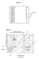
- the program implements a suitable algorithm which might, for example, be embodied by what is known as the Rainflow algorithm or by the Tank algorithm, both known in the trade, or by algorithms based on these, which convert or break down the signal detected into a plurality of basic oscillation intervals, or oscillation events, as shown for example in Figure 4 , which also shows the number of occurrences or the number of cycles, in each oscillation interval or oscillation event.
- a suitable algorithm which might, for example, be embodied by what is known as the Rainflow algorithm or by the Tank algorithm, both known in the trade, or by algorithms based on these, which convert or break down the signal detected into a plurality of basic oscillation intervals, or oscillation events, as shown for example in Figure 4 , which also shows the number of occurrences or the number of cycles, in each oscillation interval or oscillation event.
- the time variable signal P is converted into a plurality of oscillation intervals Pnm, or oscillation events, consisting of the oscillation between one value, level or threshold Pn and another value, level or threshold Pm.
- the interval P65 consists of the oscillation between a maximum pressure value, level or threshold P6 and a pressure value P5 just below the maximum pressure value P6, while the interval P64 consists of the oscillation between a maximum pressure value or level P6 and a pressure value P4 slightly lower than the previous level P5, and so on, as illustrated concisely in Figure 4 or as illustrated in specific blocks within the general block 55 in Figure 7 .
- pressure levels or thresholds P1 to P6 are predetermined, each one obtained by incrementing the previous, lower one by a predetermined value and the conversion program residing in the local processing means 20 counts the number of times, or cycles, Nnm, a certain basic oscillation, or oscillation band, generically denoted by the reference characters Pnm, included between the threshold Pn and the threshold Pm, is present in the detected signal P.
- the basic oscillation interval P65 corresponds to a certain number of occurrences, or cycles, labelled N65
- the basic oscillation interval P64 corresponds to a certain number of occurrences, or cycles, labelled N64, and so on.
- Nnm the number of occurrences, or cycles, corresponding to a respective basic oscillation interval Pnm, or event, is labelled Nnm in Figure 4 .
- Figure 7 illustrates a flow diagram schematically representing the operation of the program that determines the number of cycles corresponding to a particular basic oscillation interval, or band, Pnm of the signal detected.
- the program comprises two sub-programs called, as shown in the diagram, "filter program” and "cycle recognition program”, which can in turn be defined by or comprise other sub-programs or program routines.
- the first sub-program, the 'filter program' receives a substantially continuous signal 'P' as a function of the time 't' (as shown in the block labelled 51 or as shown in Figure 3 ) of a quantity that can indicate the stress applied to the machine structure.
- a substantially continuous signal 'P' is a function of the time 't' (as shown in the block labelled 51 or as shown in Figure 3 ) of a quantity that can indicate the stress applied to the machine structure.
- it is a pressure signal from a hydraulic cylinder of the lifting machine.
- This signal is suitably processed by the "filter program”, as shown by block 52 in Figure 7 , to identify defined values indicating the quantity "P", in particular the respective maximums and minimums, labelled K1 and K2, corresponding to respective values or thresholds Pn and Pm.
- the continuous quantity P is suitably discretized.
- the discretization of the continuous quantity P performed by the filter program is based on the predetermined thresholds, or values, such as, for example, the thresholds, or values, P1, P2, P3, P4, P5, P6, described above with reference to Figure 4 .
- the continuous signal P detected as a function of time illustrated in block 51, or in Figure 3
- a predetermined interval of time ⁇ t is converted into a discrete signal or into values corresponding to this signal and which is determined from a limited number of predetermined values or thresholds Pn, for example, the above mentioned thresholds P1, P2, P3, P4, P5, P6, as shown in block 53, Figure 7 .
- the converted signal is substantially defined by a broken line made up of a series of straight lines, each corresponding to a respective band, or interval, Pnm defined by corresponding values Pn and Pm.
- the "filter program” analyses the input quantity P as a function of time and determines the relative maximum points K1 and the relative minimum points K2 corresponding to bands or intervals Pnm of the values, or thresholds, Pn and Pm.
- the "filter program” analyses the input quantity P as a function of time and determines the relative maximum point K1, corresponding to the predetermined value P4, and the relative minimum point K2, corresponding to the predetermined value P3 in the respective band.
- the 'filter program' also considers the type of fluctuations of the quantity 'P', as shown by the dashed line 'F' in Figure 8 , within the same band.
- the "filter program” simultaneously determines and stores the relative maximum K1, corresponding to the threshold, or value, Pn, and the relative minimum K2, corresponding to the threshold, or value, Pm.
- the "filter program” simultaneously determines and stores the relative maximum K1, corresponding to the threshold, or value, P4, and the relative minimum K2, corresponding to the threshold, or value, P3.
- the determination of the points K1 and K2 may also depend on any fluctuations detected by the program within the respective band, or interval, Pnm.
- the events detected by the "filter program” correspond to the identification of relative maximums and minimums corresponding to bands, or intervals, defined by respective predetermined thresholds, or values, of the quantity P.
- a curve, or corresponding data is thus determined having the events on the x-axis, each event corresponding to respective relative maximum and minimum corresponding to respective intervals or bands defined by predetermined thresholds or values Pn, Pm.
- the number of events detected by the 'filter program' depends on the thresholds set and not on the time pattern of the quantity P.
- the second sub-program operated on the results of block 53, determined by the "filter program”, and identifies and stores the cycles, or number of occurrences, Nnm of the oscillation between the corresponding thresholds Pn and Pm (as shown in block 55, Figure 7 , and as shown as a whole in Figure 4 ), on the basis of the tank or rainflow method, and according to the discretization level set, that is to say, according to the set number Pn of thresholds, for example the thresholds P1, P2, P3, P4, P5, P6.
- the two sub-programs 52 and 54 eliminate from the memory the significant relative maximum and minimum values K1, K2 of the events of block 53, which are no longer necessary since they have already been used for counting the cycle Nnm already stored in the counters Cnm (shown in Figure 5 ).
- the program can count the crane cycles for the entire operating life of the crane without storing the entire quantity 'P' for the full duration of the operating cycle of the crane, thus using a limited amount of hardware memory.
- the "filter program” constitutes means for discretizing, or parameterizing, the continuous signal detected, that is to say, means for determining significant values K1, K2 (relative maximums and minimum) of the detected signal P, starting from predetermined thresholds or values Pn, Pm, while the "cycle recognition program” constitutes means for determining the number of cycles Nnm between corresponding thresholds Pn and
- the signal processing means 20 mounted on board the crane truck 13 comprise a corresponding program that is advantageously designed to count the number of cycles Nnm that have occurred in respective oscillation intervals Pnm of the quantity representing the stress state of the machine.
- the program residing in the memory and implemented by the on-board processing unit 20 constitutes means which, for each oscillation interval, count the number Nnm of cycles that have occurred during the respective life period of the load lifting machine.
- the counter 65 is used to store the total number of occurrences or cycles N65 corresponding to the basic oscillation interval or event P65 for the entire life of the crane up to the time of detection.
- the counter 64 is used to store the total number of occurrences or cycles N64 corresponding to the basic oscillation interval or event P64 for the entire life of the crane up to the time of detection, and so on for all the other counters.
- the processing means 20, or a program residing in and implemented by said means calculates the effective operating life in relation to the operating life limit defined for the machine, and sends this effective operating life data item to the display means 25 of the radio control 24 and/or of the display units 25' and 27.
- the program residing in the local processing means 20 constitutes means for calculating the data item defining the effective operating life, labelled CL in Figure 6 , in relation to the operating life limit defined for the machine.
- the effective operating life data item is expressed as a percentage of the operating life limit defined for the machine.
- other ways of representing the effective operating life relative to the life limit are also imaginable.
- the detected signal P corresponds to strain applied to the crane boom and is the signal indicating the pressure of a specific hydraulic cylinder forming part of the lifting machine. More specifically, the signal is the pressure signal from the main hydraulic cylinder 17 of the telescopic crane boom, that is, the hydraulic cylinder for lifting and lowering the boom or the pressure signal from the main hydraulic cylinder 17' of the fly jib 18 extending from the crane boom.
- the means 22 for detecting the time pattern of the detected signal P detect the signal in predetermined, successive intervals ⁇ t and the respective time pattern is temporarily stored in a memory of the local processing means 20.
- the means for counting the total number of cycles Cnm that occur in each oscillation interval Pnm also comprise means, in the form of a program or routine residing in, and implemented by, the local processing means 20, and which are designed to sum the number of cycles Nnm that occur in respective basic oscillation intervals Pnm of the signal detected in the corresponding time interval ⁇ t to the number of cycles Cnm already counted for all the previous detections.
- the new counts Cnm are stored and the time pattern P of the signal detected in the respective time interval ⁇ t is deleted from the memory of the local processing means 20, and, as mentioned above, the significant values are calculated from this signal.
- the system stores the next time pattern of the quantity P for a respective time interval ⁇ t in order to proceed to another counting step, as described above.
- the effective life, or effective life data item is determined from the counts Cnm of the number of cycles that have occurred in the oscillation intervals Pnm, according to the design class of the machine.
- the means for determining, or calculating, the effective life, or effective life data item comprise a program that implements an algorithm based on Miner's rule or fatigue damage rule.
- the display units 25, 25' and 27 show the effective life CL, which in this embodiment is in the form of a numeric data item expressed as a percentage of the hypothetical life for that machine design class, thus providing a piece of information that is quick and easy for the machine user to understand.
- the invention also contemplates the provision of means for determining the time pattern of the effective life, in the form of a program residing in, and implemented by, auxiliary processing means 26, preferably remote or separate from the machine 12 and from the crane truck 13, and/or residing in, and implemented by, the processing means 20 on board the machine.
- the effective life time pattern is preferably represented as a graph like the one labelled SWP shown by way of example in Figure 6 , that is displayed on the display unit 27 of the remote PC 26 and/or on the display unit 25' on board the crane truck.
- the program that determines the effective life time pattern includes instructions for displaying the effective life time pattern SWP on the basis of the counts Cnm which are periodically updated by the local processing unit 20.
- the effective life time pattern SWP is advantageously compared with a reference pattern R based on the design class and highlighting the deviations from a hypothetical, or theoretical, operating life so as to allow the user to see clearly and easily whether the machine has been subjected to more or less stress than the stress it was designed for.
- the graph of Figure 6 includes a straight line RL corresponding to the maximum working life of the machine.
- the point where the curve SWP intersects the line RL indicates the maximum operating life of the machine, corresponding to 100% of CL (crane life).
- the processing means 26 that define the time pattern SWP are placed in communication with the processing means 20 to receive from the latter the data relating to the counts Cnm.
- the count data, or counter values, Cnm are stored each time by the corresponding processing means and the effective life time pattern SWP is determined incrementally relative to the previously determined patterns on the basis of the updated count data.
- the program in the local processing means 20 or in the remote processing means 26 located, for example, at the machine's monitoring and maintenance centre includes instructions for storing the counts Cnm so as to incrementally update the graph SWP, which, as illustrated, is defined by a broken line composed of a series of straight lines.
- the effective life time pattern SWP may include sections that rise more steeply than the reference line R, corresponding to heavier duty, sections that rise less steeply than the reference line R, corresponding to lighter duty, and horizontal sections indicating periods of machine inactivity.
- the effective life time pattern SWP is represented on a graph having, on the x-axis, the years of service life and, on the y-axis, the theoretical life, also in years.
- the apparatus thus implements a procedure for determining the effective operating life, or working life, of a machine by recursively acquiring or detecting a continuous signal of a quantity representing the stress state of the machine, determining significant values of the quantity P from this continuous signal on the basis of predetermined thresholds Pn and determining, from these significant values of the quantity P, the number of occurrence cycles Nnm of corresponding oscillations Pnm between respective thresholds Pn and Pm, and then storing each number of cycles Nnm in a respective counter Cnm.
- the procedure then uses the data stored in the counters to calculate the effective operating life, or working life, of the machine.
Landscapes
- Engineering & Computer Science (AREA)
- Mechanical Engineering (AREA)
- Physics & Mathematics (AREA)
- General Physics & Mathematics (AREA)
- Control And Safety Of Cranes (AREA)
- Jib Cranes (AREA)
- Selective Calling Equipment (AREA)
- Electric Clocks (AREA)
- Control Of Ac Motors In General (AREA)
Applications Claiming Priority (1)
| Application Number | Priority Date | Filing Date | Title |
|---|---|---|---|
| IT000604A ITBO20070604A1 (it) | 2007-09-04 | 2007-09-04 | Apparato per la determinazione della durata di esercizio raggiunta da un'apparecchiatura. |
Publications (3)
| Publication Number | Publication Date |
|---|---|
| EP2079057A2 true EP2079057A2 (de) | 2009-07-15 |
| EP2079057A8 EP2079057A8 (de) | 2009-09-30 |
| EP2079057A3 EP2079057A3 (de) | 2010-11-24 |
Family
ID=40316201
Family Applications (1)
| Application Number | Title | Priority Date | Filing Date |
|---|---|---|---|
| EP08163514A Ceased EP2079057A3 (de) | 2007-09-04 | 2008-09-02 | Vorrichtung zur Bestimmung der effektiven Betriebszeit einer Maschine |
Country Status (2)
| Country | Link |
|---|---|
| EP (1) | EP2079057A3 (de) |
| IT (1) | ITBO20070604A1 (de) |
Cited By (5)
| Publication number | Priority date | Publication date | Assignee | Title |
|---|---|---|---|---|
| JP2015131701A (ja) * | 2014-01-10 | 2015-07-23 | 株式会社Ihi | デッキクレーン |
| JP2016041629A (ja) * | 2014-08-19 | 2016-03-31 | 株式会社日立産機システム | 移動装置、巻上機、クレーン装置、及びそれらに用いる車輪寿命推測方法 |
| JP2017039611A (ja) * | 2016-12-01 | 2017-02-23 | 株式会社日立産機システム | 巻上機寿命計算装置 |
| CN112326284A (zh) * | 2020-10-19 | 2021-02-05 | 南京中船绿洲机器有限公司 | 一种基于任务剖面的电动甲板起重机可靠性试验方法 |
| CN114270161A (zh) * | 2019-08-21 | 2022-04-01 | 拉普兰塔-拉登理工大学 | 用于监测材料疲劳的系统和方法 |
Citations (1)
| Publication number | Priority date | Publication date | Assignee | Title |
|---|---|---|---|---|
| US4752012A (en) * | 1986-08-29 | 1988-06-21 | Harnischfeger Corporation | Crane control means employing load sensing devices |
Family Cites Families (4)
| Publication number | Priority date | Publication date | Assignee | Title |
|---|---|---|---|---|
| US5531122A (en) * | 1994-02-28 | 1996-07-02 | Caterpillar Inc. | Fatigue analysis and warning system |
| JP3188838B2 (ja) * | 1996-03-28 | 2001-07-16 | 株式会社福岡機器製作所 | レインフロー法による疲労解析用データ採取装置 |
| FI20000325A0 (fi) * | 2000-02-15 | 2000-02-15 | Koivisto Marja Liisa | Menetelmä rakenteen rasituksen määrittämiseksi |
| EP1278695A1 (de) * | 2000-03-28 | 2003-01-29 | David J. Higgins | Teleskopausleger |
-
2007
- 2007-09-04 IT IT000604A patent/ITBO20070604A1/it unknown
-
2008
- 2008-09-02 EP EP08163514A patent/EP2079057A3/de not_active Ceased
Patent Citations (1)
| Publication number | Priority date | Publication date | Assignee | Title |
|---|---|---|---|---|
| US4752012A (en) * | 1986-08-29 | 1988-06-21 | Harnischfeger Corporation | Crane control means employing load sensing devices |
Cited By (6)
| Publication number | Priority date | Publication date | Assignee | Title |
|---|---|---|---|---|
| JP2015131701A (ja) * | 2014-01-10 | 2015-07-23 | 株式会社Ihi | デッキクレーン |
| JP2016041629A (ja) * | 2014-08-19 | 2016-03-31 | 株式会社日立産機システム | 移動装置、巻上機、クレーン装置、及びそれらに用いる車輪寿命推測方法 |
| JP2017039611A (ja) * | 2016-12-01 | 2017-02-23 | 株式会社日立産機システム | 巻上機寿命計算装置 |
| CN114270161A (zh) * | 2019-08-21 | 2022-04-01 | 拉普兰塔-拉登理工大学 | 用于监测材料疲劳的系统和方法 |
| US20220317004A1 (en) * | 2019-08-21 | 2022-10-06 | Lappeenrannan-Lahden Teknillinen Yliopisto Lut | A system and a method for monitoring material fatigue |
| CN112326284A (zh) * | 2020-10-19 | 2021-02-05 | 南京中船绿洲机器有限公司 | 一种基于任务剖面的电动甲板起重机可靠性试验方法 |
Also Published As
| Publication number | Publication date |
|---|---|
| EP2079057A8 (de) | 2009-09-30 |
| ITBO20070604A1 (it) | 2009-03-05 |
| EP2079057A3 (de) | 2010-11-24 |
Similar Documents
| Publication | Publication Date | Title |
|---|---|---|
| CN101391725B (zh) | 臂架型起重机工作状态记录及安全保护系统 | |
| EP2079057A2 (de) | Vorrichtung zur Bestimmung der effektiven Betriebszeit einer Maschine | |
| KR101087045B1 (ko) | 호이스트 및 크레인의 안전진단 방법 | |
| US20220081880A1 (en) | Device for determining the actual state and/or the remaining service life of a construction, materials-handling and/or conveyor machine | |
| RU2014148911A (ru) | Система контроля крана | |
| US12054914B2 (en) | Method, device and user interface for presentation of information describing a running operating condition of a demolition robot | |
| KR20100069722A (ko) | 크레인 양중 운영 시스템 및 그를 이용하는 방법 | |
| US20180024544A1 (en) | Damage Estimation Device | |
| DE112015005528T5 (de) | Kontrollgerät und Verfahren zur Bestimmung der Betriebsbereitschaft einer mit einem Druckmedium betriebenen Vorrichtung | |
| CN111158307A (zh) | 一种塔机故障诊断系统 | |
| CN110941234A (zh) | 一种随车吊运行管理用的控制系统 | |
| CN205442423U (zh) | 一种起重机的控制及监控管理系统 | |
| DE102020208295A1 (de) | Ausfallvorhersagesystem | |
| JP3820293B2 (ja) | 移動作業機械の監視装置 | |
| EP4201865B1 (de) | Arbeitsgerätesystem und verfahren des arbeitsgerätesystems | |
| US10430057B2 (en) | Operator interface for wireless sensing and system and method thereof | |
| JP5114038B2 (ja) | エレベータの機能可変型遠隔監視システム | |
| CN118535848A (zh) | 一种基于卡调终端的车铲出动台数统计方法及系统 | |
| CN211855413U (zh) | 登机廊桥在线预警与故障诊断装置 | |
| EP4174014A1 (de) | Ladekransystem | |
| CN202190543U (zh) | 联合收割机用智能检测报警器 | |
| JP2002011665A (ja) | ショットブラスト装置モニタシステム | |
| JP3663268B2 (ja) | 作業機械の稼働状態監視装置 | |
| CN201402476Y (zh) | 振动机械随机监控装置 | |
| JPH06116988A (ja) | 建設機械のメンテナンスモニタ装置 |
Legal Events
| Date | Code | Title | Description |
|---|---|---|---|
| PUAI | Public reference made under article 153(3) epc to a published international application that has entered the european phase |
Free format text: ORIGINAL CODE: 0009012 |
|
| AK | Designated contracting states |
Kind code of ref document: A2 Designated state(s): AT BE BG CH CY CZ DE DK EE ES FI FR GB GR HR HU IE IS IT LI LT LU LV MC MT NL NO PL PT RO SE SI SK TR |
|
| AX | Request for extension of the european patent |
Extension state: AL BA MK RS |
|
| PUAL | Search report despatched |
Free format text: ORIGINAL CODE: 0009013 |
|
| RAP1 | Party data changed (applicant data changed or rights of an application transferred) |
Owner name: EFFER S.P.A. |
|
| AK | Designated contracting states |
Kind code of ref document: A3 Designated state(s): AT BE BG CH CY CZ DE DK EE ES FI FR GB GR HR HU IE IS IT LI LT LU LV MC MT NL NO PL PT RO SE SI SK TR |
|
| AX | Request for extension of the european patent |
Extension state: AL BA MK RS |
|
| 17P | Request for examination filed |
Effective date: 20110607 |
|
| AKX | Designation fees paid |
Designated state(s): AT BE BG CH CY CZ DE DK EE ES FI FR GB GR HR HU IE IS IT LI LT LU LV MC MT NL NO PL PT RO SE SI SK TR |
|
| 17Q | First examination report despatched |
Effective date: 20110818 |
|
| STAA | Information on the status of an ep patent application or granted ep patent |
Free format text: STATUS: THE APPLICATION HAS BEEN REFUSED |
|
| 18R | Application refused |
Effective date: 20130202 |